Spin-photon interface and spin-controlled photon switching in a nanobeam waveguide
Access to the electron spin is at the heart of many protocols for integrated and distributed quantum-information processing Kimble (2008); Duan and Kimble (2004); Van Meter et al. (2010); Gao et al. (2015). For instance, interfacing the spin-state of an electron and a photon can be utilized to perform quantum gates between photons Duan and Kimble (2004); Hacker et al. (2016) or to entangle remote spin states Delteil et al. (2016); Hucul et al. (2015); Sipahigil et al. (2016); Cirac et al. (1997). Ultimately, a quantum network of entangled spins constitutes a new paradigm in quantum optics Kimble (2008). Towards this goal, an integrated spin-photon interface would be a major leap forward. Here we demonstrate an efficient and optically programmable interface between the spin of an electron in a quantum dot and photons in a nanophotonic waveguide. The spin can be deterministically prepared with a fidelity of 96%. Subsequently the system is used to implement a “single-spin photonic switch”, where the spin state of the electron directs the flow of photons through the waveguide. The spin-photon interface may enable on-chip photon-photon gates Duan and Kimble (2004), single-photon transistors Chang et al. (2007), and efficient photonic cluster state generation Lindner and Rudolph (2009).
Solid-state quantum emitters embedded in planar nanostructures offer a scalable route to integrated light-matter interfaces Sipahigil et al. (2016); Faez et al. (2014); Lodahl et al. (2015). Among these emitters, InGaAs quantum dots are arguably the most developed platform. Quantum dots have been integrated in various nanostructures with near-unity coupling efficiencies Lund-Hansen et al. (2008); Arcari et al. (2014); Claudon et al. (2010); Laucht et al. (2012); Makhonin et al. (2014). Such a high coupling efficiency has enabled near deterministic and indistinguishable single-photon sources Ding et al. (2016); Kiršanské et al. (2017), as well as single-photon level nonlinearities Javadi et al. (2015); De Santis et al. (2017); Bennett et al. (2016). Furthermore, chiral light-matter interaction leading to directional photon emission and scattering Luxmoore et al. (2013); Söllner et al. (2015); Coles et al. (2016) has opened new prospects for integrated quantum-information processing Lodahl et al. (2017).
Significant progress has been made on coherent control of the spin state of electrons and holes in quantum dots Kroutvar et al. (2004); Gerardot et al. (2008); Atatüre et al. (2006); Warburton (2013); Press et al. (2010); Stockill et al. (2016), spin-photon entanglement De Greve et al. (2012); Gao et al. (2012), and spin-spin entanglement Delteil et al. (2016). However, coupling of the spin of quantum dots to planar nanostructures is so far largely unexplored, and has only been studied with in-plane magnetic fields (Voigt geometry) Carter et al. (2013); Sun et al. (2016), and with probabilistically-charged quantum dots Sun et al. (2016). The first challenge is that the quantum dot needs to be placed in thin optical membranes (typically with a thickness below ) to obtain single-mode operation and therefore efficient light-matter interaction. Achieving deterministic control over the charge state of the quantum dot in thin membranes has been challenging Pinotsi et al. (2011), and has only been demonstrated with samples having a large leakage current ( ) running through the sample Carter et al. (2013); Sweeney et al. (2014); Pinotsi et al. (2011), which may degrade the spin properties of the quantum dot. As a result, quantum dot spin-state preparation has only been achieved with in-plane external magnetic fields Carter et al. (2013); Sun et al. (2016), which do not require long spin lifetimes Emary et al. (2007). Secondly, many groups have focused on achieving strong coupling between the spin state of the quantum dot and a narrow-linewidth cavity Carter et al. (2013); Lagoudakis et al. (2013); Sweeney et al. (2014); Sun et al. (2016). However, this approach is challenging to implement in spin-photon interfaces since the narrow cavity bandwidth implies that the two different spin states cannot simultaneously be well-coupled. Complete control of the spin state of a quantum dot involves driving and detecting four different optical transitions simultaneously, c.f, Fig. 1a.
Nanophotonic waveguides offer high coupling efficiencies of embedded quantum emitters over a wide spectral bandwidth Lodahl et al. (2015), and appear to be an ideal platform for realizing efficient spin-photon interfaces. This is the setting referred to as the “1D quantum emitter”, where the coupling of the emitter to a single optical mode is so pronounced that deterministic photon-emitter coupling may be achieved. In the present work we demonstrate an integrated interface between the spin state of an electron in a quantum dot and the optical mode of a nanobeam waveguide. We use this interface to realize a proof-of-concept optically programmable photon switch, which is controlled by the spin state of the quantum dot. We achieve deterministic charging of the quantum dot at low bias voltages and with very low parasitic leakage current (, corresponding to a current density of ), which allows us to demonstrate high-fidelity spin state preparation while applying a magnetic field parallel to the growth axis of the quantum dot (Faraday geometry). The spin preparation fidelities approach 96% for a spin lifetime of . We observe that the diagonal decay rate () is two orders of magnitude smaller than the vertical decay rate (), . Together with the long spin lifetime, , this is the favourable condition for realizing high-fidelity spin state preparation Warburton (2013); Gao et al. (2015) as required for photon-photon gates and single-photon transistors Duan and Kimble (2004); Chang et al. (2007). Finally, we show that the quantum dot modifies the transmission through the waveguide, and, by deterministically preparing the spin state of the electron by fast optical control, we can switch the transmission of the waveguide. The observed spin-dependent transmission can be utilized as a programmable switch for routing single photons on a chip. Contrary to operation in the Voigt geometry, the Faraday configuration features chiral light-matter interaction and may enable nonreciprocal light transport Söllner et al. (2015), which can be employed for novel quantum photonics devices such as on-chip single-photon circulators Scheucher et al. (2016), integrated isolators Sayrin et al. (2015), and building blocks for distributed quantum networks Mahmoodian et al. (2016).
Level structure
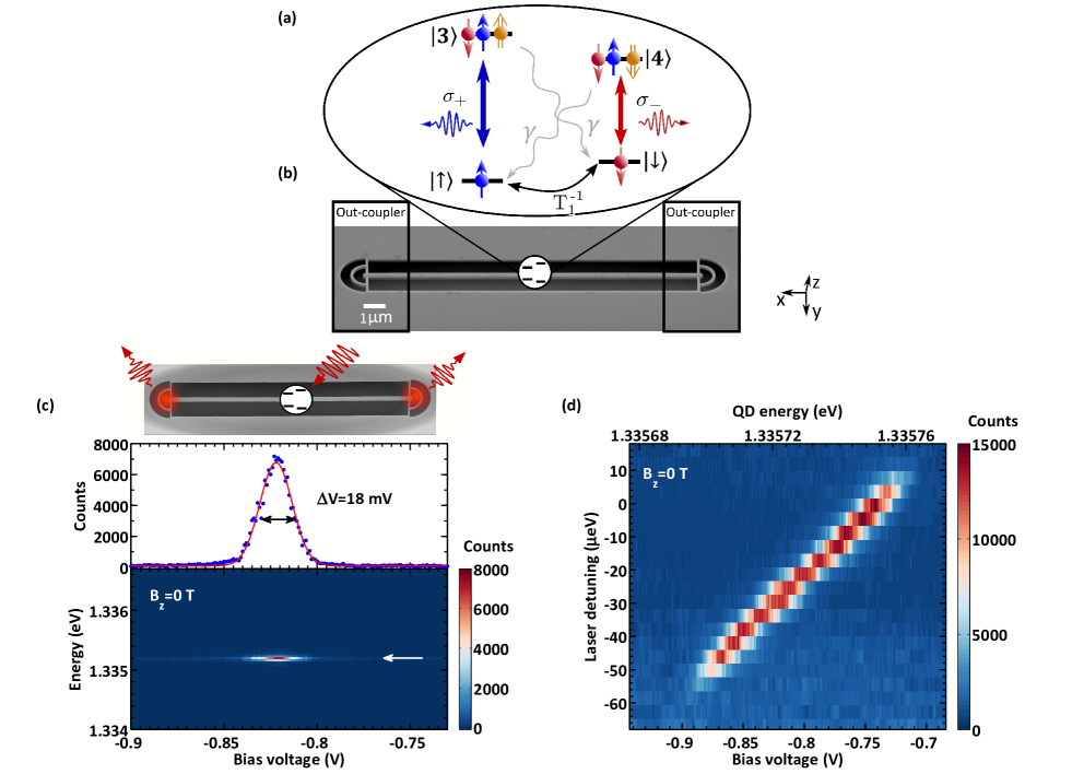
Figure 1a shows the level structure of a negatively charged quantum dot under influence of a static magnetic field along the growth axis () Warburton (2013). In the ground state, the spin of the trapped electron is oriented parallel or anti-parallel to the growth axis, which are labeled as spin-up () and spin-down states (), respectively. The two excited states are negatively-charged excitons (), and consist of two spin-paired electrons and a single hole. The vertical transitions are circularly polarized ( and ). The diagonal transitions are weakly allowed due to the in-plane Overhauser field and heavy-hole light-hole mixing in the valence band of the quantum dot, with the latter being the dominant mechanism at higher magnetic fields Dreiser et al. (2008).
Sample design and characterization
Figure 1b shows a scanning electron micrograph (SEM) of a nanobeam waveguide, terminated with grating out-couplers at the two ends. A layer of InGaAs quantum dots is positioned in the centre of the membrane inside a P-I-N-I-N diode grown along the -direction Löbl et al. (2017). The design of the diode facilitates deterministic charging of the quantum dot as well as tuning of its energy levels by applying a bias voltage, see Supplementary Information for details.
The colour plot in Fig. 1c shows a spectrum of the emission from under weak resonant excitation at . The laser is fixed at and the energy of the quantum dot transition is tuned by changing the bias voltage. The top panel shows a line-cut through the laser energy. The linewidth of the resonance is ( the natural linewidth), where the broadening is attributed to charge noise from the environment of the quantum dot Kuhlmann et al. (2013); Nguyen et al. (2013), although not a fundamental limitation in nanobeam waveguides where narrow linewidth quantum dots were recently observed Kiršanské et al. (2017). Figure 1d shows a plateau map of the resonance fluorescence from the transition as a function of excitation laser energy and the bias voltage. The relevant transition energy range is between and , where the quantum dot is charged with a single electron in the ground state. Below this plateau region the quantum dot is empty and above the quantum dot is charged with two electrons and hence the fluorescence from vanishes Warburton et al. (2000); Högele et al. (2004). In the centre of the plateau, the single-electron charged state of the quantum dot is a stable state, and the spin state of the electron is only influenced by second-order processes such as co-tunneling with the back contact Smith et al. (2005); Dreiser et al. (2008), or by Auger recombination Kurzmann et al. (2016).
Optical spin state preparation
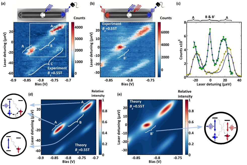
To prepare two optically accessible spin ground states with an energy difference larger than the transition linewidth, we lift the degeneracy by inducing a Zeeman shift at . We probe the and states through resonance fluorescence from the exciton. Figure 2a shows the plateau map of the exciton. The emission plateau (regions A and B) originates from the high energy (blue) transition of the negatively-charged exciton, while region C corresponds to emission from the low energy (red) transition. We note that the blue transition is times brighter than the red transition, which is due to chiral light-matter interaction Söllner et al. (2015); Coles et al. (2016); Lodahl et al. (2017). At the central part of the plateau, region B, optical spin-pumping takes place and the emission from is suppressed due to spin-non-conserving diagonal transitions. At the edges of the plateaus, region A, the electron is strongly coupled to the Fermi-sea in the back contact and its spin is randomized over short time scales ( 10s of nano-seconds) Smith et al. (2005); Dreiser et al. (2008) which hinders spin-pumping. At these points, the fluorescence is times brighter than in the centre, cf. line-cut data in Fig. 2c. By comparing the resonance fluorescence intensity at the edge of the plateau with the emission at the centre of the plateau, we extract a spin preparation fidelity , where is the density matrix of the prepared state. At higher magnetic fields we achieve fidelities up to , see Supplementary Information for details.
To confirm optical spin pumping, we perform a two-colour resonance fluorescence experiment Kroner et al. (2008), where one laser is fixed at the centre of the plateau of the red transition, while the frequency of the second laser is scanned. Figure 2b shows the two-colour plateau map of the exciton. When the two lasers are on resonance with the blue and red transitions simultaneously, , they cancel each others’ spin-pumping effect and the resonance fluorescence from the quantum dot is recovered. Figure 2d and 2e are the theoretical models of the data, see Supplementary Information for details. The experimental behavior is quantitatively described by the theory, for . We also extract using time resolved measurements, the details are described in the Supplementary Information. may also be extracted directly by pump-delay-probe experiments where we obtain , in very good agreement with the parameters extracted from modeling the data in Fig. 2a. We emphasize that the observed spin lifetime in the photonic nanostructure is longer than the longest spin coherence time reported with quantum dots Wüst et al. (2016) even after implementing spin-echo techniques Press et al. (2010), hence the spin relaxation will not limit any processes which depend on spin coherence.
Spin-controlled photon switching
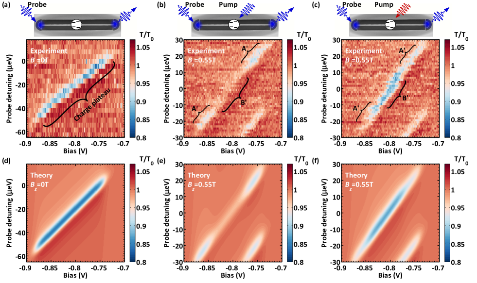
A quantum emitter coupled to a single optical mode can modify the light transmission properties significantly Javadi et al. (2015); Shen and Fan (2005); Chang et al. (2007). For an efficient coupling this interaction can be sensitive at the single-photon level. The colour map in Fig. 3a shows the normalized transmission of a weak probe as a function of its energy and the bias voltage of the diode at . When the probe is on resonance with the transition, the transmission of the probe is reduced due to the interaction with the transition Javadi et al. (2015); Shen and Fan (2005), where the quantum dot scatters one photon at a time. This is observed as a dip in the plateau map in Fig. 3a. We observe a maximum contrast of 15% in the transmission, which is mainly limited by the inhomogeneous broadening of the quantum dot transition.
To implement a spin-state dependent interaction between the quantum dot and the waveguide mode, we use optical spin pumping to deterministically prepare the spin state of the quantum dot. A strong laser pulse (pump) with a duration of incident from the top of the waveguide prepares the spin state of the electron. Subsequently, a weak pulse (probe) with a duration of , coupled in and out via the gratings, probes the single-photon transmission through the waveguide. Figure 3b shows the normalized transmission through the waveguide while the probe and pump pulses are on resonance. In the centre of the plateau, , the pump pulse prepares the spin of the electron in with a high fidelity. This state is off resonance with the probe and hence the transmission recovers to the level , which is the level encountered when the probe is far from resonance of the quantum dot transition. At the edges of the plateau, , the transmission of the probe is reduced due to inefficient spin state preparation. Figure 3c shows the transmission of the waveguide while the pump laser is detuned by from the probe. In this case, the pump prepares the spin of the electron in the state, which is on resonance with the probe. As a result, the probe pulse interacts with the blue transition of the exciton. At the centre of the plateau () the transmission of the waveguide is reduced to 0.87, similar to the value found without an external magnetic field.
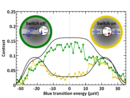
The ability to prepare a spin deterministically and thereby control the waveguide transmission constitutes a proof-of-concept realization of a switch for single photons. Figure 4 shows the contrast of the transmission through the waveguide as a function of the energy detuning. The transmission is switched by tuning of the pump pulse to either the red or the blue transition of the quantum dot. The ON and OFF states of the switch correspond to the case where the spin of the quantum dot is prepared in and , respectively. We observe a switching ratio of more than a factor of 4 between ON and OFF states, which could be improved further by reducing spectral diffusion due to residual charge noise broadening. Ultimately the switch could be operated in a genuine quantum regime if the spin was initially prepared in a coherent superposition state. Such a quantum switch could create a photonic Schrödinger cat state when applied to a weak coherent state Chang et al. (2007).
It is instructive to benchmark the reported performance of all-optical switching. The pump power on the sample for the data in Fig. 4 is around for a duration of , which corresponds to 40 femto joules per pump cycle. During each switching cycle the quantum dot scatters photons, which is about 100 photons for the measurements reported here Chang et al. (2007). The average energy to switch one photon is therefore femto joules per switched photon, which is comparable to the switching energy of cavity-based switches Fushman et al. (2008); Volz et al. (2012). The energy could be further reduced by up to two orders of magnitude by directly launching the pump pulse inside the waveguide. The switching time in the present work is significantly slower than the above mentioned approaches based on the strong coupling of a quantum dot exciton transition to a cavity. However, the present approach offers the advantage of having access to the quantum memory in the form of the ground state electron spin, which is the prerequisite for many quantum-information applications Lodahl (2017).
We have demonstrated all-optical control of a single electron spin in a quantum dot efficiently coupled to a nanophotonic waveguide. Based on this approach, a single spin controls the flow of photons through the waveguide. The work opens a range of new opportunities in quantum optics for exploiting deterministic photon-spin coupling, e.g., for generating long strings of photonic cluster states Schwartz et al. (2016); Lindner and Rudolph (2009), a high-fidelity photon-photon gate Duan and Kimble (2004) or single-photon transistors Chang et al. (2007). Extending to the coupling of two quantum dots would enable to construct a fundamental building block for a distributed photonic quantum network Mahmoodian et al. (2016). For these potential applications it is favorable to work in the Faraday geometry (external magnetic field along the growth direction) as is the case here, since the operation fidelity scales as Chang et al. (2007), where was reported here. One challenge, however, is the coupling of the electron spin to the noisy nuclear bath leading to electron spin dephasing. Recent work has demonstrated how to significantly reduce the noise on the Overhauser field by feedback control of the nuclear ensemble Xu et al. (2009); Kuhlmann et al. (2015); Éthier-Majcher et al. (2017).
Acknowledgements.
We acknowledge N. J. Taba, and C. L. Dreeßen for help during the initial stages of the measurements. We gratefully acknowledge financial support from the European Research Council (ERC Advanced Grant “SCALE”), Innovation Fund Denmark (Quantum Innovation Center “Qubiz”), and the Danish Council for Independent Research. IS, MCL & RJW acknowledge support from SNF (project 200020_156637) and NCCR QSIT. A.L. and A.D.W. gratefully acknowledge support of BMBF - Q.com-H 16KIS0109 and the DFG - TRR 160. This project has received funding from the European Unions Horizon 2020 research and innovation programme under the Marie Skodowska-Curie grant agreement No. 747866 (EPPIC).Contributions
A.J., D.D., M.H.A., and T.S. carried out the optical experiment with input from I.S., R.J.W., and P.L. A.J., M.H.A., and S.M. performed the theory. M.C.L., I.S., A.L., and R.J.W. designed the heterostructure. R.S., A.L., and A.D.W. grew the wafer. C.P., T.P., S.S., and L.M. designed and fabricated the sample. A.J. and P.L. wrote the manuscript with input from all authors.
References
- Kimble (2008) H. J. Kimble, Nature 453, 1023 (2008).
- Duan and Kimble (2004) L. M. Duan and H. J. Kimble, Phys. Rev. Lett. 92, 127902 (2004).
- Van Meter et al. (2010) R. Van Meter, T. D. Ladd, A. G. Fowler, and Y. Yamamoto, Int. J. Quantum Inf. 8, 295 (2010).
- Gao et al. (2015) W. Gao, A. Imamoglu, H. Bernien, and R. Hanson, Nat. Photonics 9, 363 (2015).
- Hacker et al. (2016) B. Hacker, S. Welte, G. Rempe, and S. Ritter, Nature 536, 193 (2016).
- Delteil et al. (2016) A. Delteil, Z. Sun, W.-b. Gao, E. Togan, S. Faelt, and A. Imamoğlu, Nat. Phys. 12, 218 (2016).
- Hucul et al. (2015) D. Hucul, I. V. Inlek, G. Vittorini, C. Crocker, S. Debnath, S. M. Clark, and C. Monroe, Nat. Phys. 11, 37 (2015).
- Sipahigil et al. (2016) A. Sipahigil, R. E. Evans, D. D. Sukachev, M. J. Burek, J. Borregaard, M. K. Bhaskar, C. T. Nguyen, J. L. Pacheco, H. A. Atikian, C. Meuwly, R. M. Camacho, F. Jelezko, E. Bielejec, H. Park, M. Lončar, and M. D. Lukin, Science 354, 847 (2016).
- Cirac et al. (1997) J. I. Cirac, P. Zoller, H. J. Kimble, and H. Mabuchi, Phys. Rev. Lett. 78, 3221 (1997).
- Chang et al. (2007) D. E. Chang, A. S. Sørensen, E. A. Demler, and M. D. Lukin, Nat. Phys. 3, 807 (2007).
- Lindner and Rudolph (2009) N. H. Lindner and T. Rudolph, Phys. Rev. Lett. 103, 113602 (2009).
- Faez et al. (2014) S. Faez, P. Türschmann, H. R. Haakh, S. Götzinger, and V. Sandoghdar, Phys. Rev. Lett. 113, 213601 (2014).
- Lodahl et al. (2015) P. Lodahl, S. Mahmoodian, and S. Stobbe, Rev. Mod. Phys. 87, 347 (2015).
- Lund-Hansen et al. (2008) T. Lund-Hansen, S. Stobbe, B. Julsgaard, H. Thyrrestrup, T. Sünner, M. Kamp, A. Forchel, and P. Lodahl, Phys. Rev. Lett. 101, 113903 (2008).
- Arcari et al. (2014) M. Arcari, I. Söllner, A. Javadi, S. Lindskov Hansen, S. Mahmoodian, J. Liu, H. Thyrrestrup, E. H. Lee, J. D. Song, S. Stobbe, and P. Lodahl, Phys. Rev. Lett. 113, 093603 (2014).
- Claudon et al. (2010) J. Claudon, J. Bleuse, N. S. Malik, M. Bazin, P. Jaffrennou, N. Gregersen, C. Sauvan, P. Lalanne, and J.-M. Gérard, Nat. Photonics 4, 174 (2010).
- Laucht et al. (2012) A. Laucht, S. Pütz, T. Günthner, N. Hauke, R. Saive, S. Frédérick, M. Bichler, M.-C. Amann, A. Holleitner, M. Kaniber, and J. J. Finley, Phys. Rev. X 2, 011014 (2012).
- Makhonin et al. (2014) M. Makhonin, J. Dixon, R. Coles, B. Royall, I. J. Luxmoore, E. Clarke, M. Hugues, M. Skolnick, and A. M. Fox, Nano lett. 14, 6997 (2014).
- Ding et al. (2016) X. Ding, Y. He, Z.-C. Duan, N. Gregersen, M.-C. Chen, S. Unsleber, S. Maier, C. Schneider, M. Kamp, S. Höfling, C.-Y. Lu, and J.-W. Pan, Phys. Rev. Lett. 116, 020401 (2016).
- Kiršanské et al. (2017) G. Kiršanské, H. Thyrrestrup, R. S. Daveau, C. L. Dreeßen, T. Pregnolato, L. Midolo, P. Tighineanu, A. Javadi, S. Stobbe, R. Schott, A. Ludwig, A. D. Wieck, S. I. Park, J. D. Song, A. V. Kuhlmann, I. Söllner, M. C. Löbl, R. J. Warburton, and P. Lodahl, arXiv:1701.08131 (2017).
- Javadi et al. (2015) A. Javadi, I. Söllner, M. Arcari, S. L. Hansen, L. Midolo, S. Mahmoodian, G. Kiršanskė, T. Pregnolato, E. Lee, J. Song, S. Stobbe, and P. Lodahl, Nat. Commun. 6, 8655 (2015).
- De Santis et al. (2017) L. De Santis, C. Antón, B. Reznychenko, N. Somaschi, G. Coppola, J. Senellart, C. Gómez, A. Lemaître, I. Sagnes, A. G. White, L. Lanco, A. Auffèves, and P. Senellart, Nat. Nanotechnol. 12, 663 (2017).
- Bennett et al. (2016) A. Bennett, J. Lee, D. Ellis, I. Farrer, D. Ritchie, and A. Shields, Nat. Nanotechnol. 11, 857 (2016).
- Luxmoore et al. (2013) I. J. Luxmoore, N. A. Wasley, A. J. Ramsay, A. C. T. Thijssen, R. Oulton, M. Hugues, S. Kasture, V. G. Achanta, A. M. Fox, and M. S. Skolnick, Phys. Rev. Lett. 110, 037402 (2013).
- Söllner et al. (2015) I. Söllner, S. Mahmoodian, S. L. Hansen, L. Midolo, A. Javadi, G. Kiršanské, T. Pregnolato, H. El-Ella, E. H. Lee, J. D. Song, S. Stobbe, and P. Lodahl, Nat. Nanotechnol. 10, 775 (2015).
- Coles et al. (2016) R. Coles, D. Price, J. Dixon, B. Royall, E. Clarke, P. Kok, M. Skolnick, A. Fox, and M. Makhonin, Nat. Commun. 7, 11183 (2016).
- Lodahl et al. (2017) P. Lodahl, S. Mahmoodian, S. Stobbe, A. Rauschenbeutel, P. Schneeweiss, J. Volz, H. Pichler, and P. Zoller, Nature 541, 473 (2017).
- Kroutvar et al. (2004) M. Kroutvar, Y. Ducommun, D. Heiss, M. Bichler, D. Schuh, G. Abstreiter, and J. J. Finley, Nature 432, 81 (2004).
- Gerardot et al. (2008) B. D. Gerardot, D. Brunner, P. A. Dalgarno, P. Öhberg, S. Seidl, M. Kroner, K. Karrai, N. G. Stoltz, P. M. Petroff, and R. J. Warburton, Nature 451, 441 (2008).
- Atatüre et al. (2006) M. Atatüre, J. Dreiser, A. Badolato, A. Högele, K. Karrai, and A. Imamoglu, Science 312, 551 (2006).
- Warburton (2013) R. J. Warburton, Nat. Mat. 12, 483 (2013).
- Press et al. (2010) D. Press, K. De Greve, P. L. McMahon, T. D. Ladd, B. Friess, C. Schneider, M. Kamp, S. Höfling, A. Forchel, and Y. Yamamoto, Nat. Photonics 4, 367 (2010).
- Stockill et al. (2016) R. Stockill, C. Le Gall, C. Matthiesen, L. Huthmacher, E. Clarke, M. Hugues, and M. Atatüre, Nat. Commun. 7, 12745 (2016).
- De Greve et al. (2012) K. De Greve, L. Yu, P. L. McMahon, J. S. Pelc, C. M. Natarajan, N. Y. Kim, E. Abe, S. Maier, C. Schneider, M. Kamp, S. Höfling, R. H. Hadfield, A. Forchel, M. M. Fejer, and Y. Yamamoto, Nature 491, 421 (2012).
- Gao et al. (2012) W. Gao, P. Fallahi, E. Togan, J. Miguel-Sanchez, and A. Imamoglu, Nature 491, 426 (2012).
- Carter et al. (2013) S. G. Carter, T. M. Sweeney, M. Kim, C. S. Kim, D. Solenov, S. E. Economou, T. L. Reinecke, L. Yang, A. S. Bracker, and D. Gammon, Nat. Photonics 7, 329 (2013).
- Sun et al. (2016) S. Sun, H. Kim, G. S. Solomon, and E. Waks, Nat. Nanotechnol. 11, 539 (2016).
- Pinotsi et al. (2011) D. Pinotsi, P. Fallahi, J. Miguel.Sanchez, and A. Imamoglu, IEEE J. Quant Electron. 47, 1371 (2011).
- Sweeney et al. (2014) T. M. Sweeney, S. G. Carter, A. S. Bracker, M. Kim, C. S. Kim, L. Yang, P. M. Vora, P. G. Brereton, E. R. Cleveland, and D. Gammon, Nat. Photonics 8, 442 (2014).
- Emary et al. (2007) C. Emary, X. Xu, D. G. Steel, S. Saikin, and L. J. Sham, Phys. Rev. Lett. 98, 047401 (2007).
- Lagoudakis et al. (2013) K. G. Lagoudakis, K. Fischer, T. Sarmiento, A. Majumdar, A. Rundquist, J. Lu, M. Bajcsy, and J. Vučković, New J. Phys. 15, 113056 (2013).
- Scheucher et al. (2016) M. Scheucher, A. Hilico, E. Will, J. Volz, and A. Rauschenbeutel, Science 354, 1577 (2016).
- Sayrin et al. (2015) C. Sayrin, C. Junge, R. Mitsch, B. Albrecht, D. O’Shea, P. Schneeweiss, J. Volz, and A. Rauschenbeutel, Phys. Rev. X 5, 041036 (2015).
- Mahmoodian et al. (2016) S. Mahmoodian, P. Lodahl, and A. S. Sørensen, Phys. Rev. Lett. 117, 240501 (2016).
- Dreiser et al. (2008) J. Dreiser, M. Atatüre, C. Galland, T. Müller, A. Badolato, and A. Imamoglu, Phys. Rev. B 77, 075317 (2008).
- Löbl et al. (2017) M. C. Löbl, I. Söllner, A. Javadi, T. Pregnolato, R. Schott, L. Midolo, A. V. Kuhlmann, S. Stobbe, A. D. Wieck, P. Lodahl, A. Ludwig, and R. J. Warburton, arXiv:1708.00520 (2017).
- Kuhlmann et al. (2013) A. V. Kuhlmann, J. Houel, A. Ludwig, L. Greuter, D. Reuter, A. D. Wieck, M. Poggio, and R. J. Warburton, Nat. Phys. 9, 570 (2013).
- Nguyen et al. (2013) H. S. Nguyen, G. Sallen, M. Abbarchi, R. Ferreira, C. Voisin, P. Roussignol, G. Cassabois, and C. Diederichs, Phys. Rev. B 87, 115305 (2013).
- Warburton et al. (2000) R. J. Warburton, C. Schäflein, D. Haft, F. Bickel, A. Lorke, K. Karrai, J. M. Garcia, W. Schoenfeld, and P. M. Petroff, Nature 405, 926 (2000).
- Högele et al. (2004) A. Högele, S. Seidl, M. Kroner, K. Karrai, R. J. Warburton, B. D. Gerardot, and P. M. Petroff, Phys. Rev. Lett. 93, 217401 (2004).
- Smith et al. (2005) J. M. Smith, P. A. Dalgarno, R. J. Warburton, A. O. Govorov, K. Karrai, B. D. Gerardot, and P. M. Petroff, Phys. Rev. Lett. 94, 197402 (2005).
- Kurzmann et al. (2016) A. Kurzmann, A. Ludwig, A. D. Wieck, A. Lorke, and M. Geller, Nano lett. 16, 3367 (2016).
- Kroner et al. (2008) M. Kroner, K. M. Weiss, B. Biedermann, S. Seidl, A. W. Holleitner, A. Badolato, P. M. Petroff, P. Öhberg, R. J. Warburton, and K. Karrai, Phys. Rev. B 78, 075429 (2008).
- Wüst et al. (2016) G. Wüst, M. Munsch, F. Maier, A. V. Kuhlmann, A. Ludwig, A. D. Wieck, D. Loss, M. Poggio, and R. J. Warburton, Nat. Nanotechnol. 11, 885 (2016).
- Shen and Fan (2005) J. T. Shen and S. Fan, Opt. Lett. 30, 2001 (2005).
- Fushman et al. (2008) I. Fushman, D. Englund, A. Faraon, N. Stoltz, P. Petroff, and J. Vučković, Science 320, 769 (2008).
- Volz et al. (2012) T. Volz, A. Reinhard, M. Winger, A. Badolato, K. J. Hennessy, E. L. Hu, and A. Imamoğlu, Nat. Photonics 6, 605 (2012).
- Lodahl (2017) P. Lodahl, arXiv:1707.02094 (2017).
- Schwartz et al. (2016) I. Schwartz, D. Cogan, E. R. Schmidgall, Y. Don, L. Gantz, O. Kenneth, N. H. Lindner, and D. Gershoni, Science 354, 343 (2016).
- Xu et al. (2009) X. Xu, W. Yao, B. Sun, D. G. Steel, A. S. Bracker, D. Gammon, and L. J. Sham, Nature 459, 1105 (2009).
- Kuhlmann et al. (2015) A. V. Kuhlmann, J. H. Prechtel, J. Houel, A. Ludwig, D. Reuter, A. D. Wieck, and R. J. Warburton, 6, 8204 (2015).
- Éthier-Majcher et al. (2017) G. Éthier-Majcher, D. Gangloff, R. Stockill, E. Clarke, M. Hugues, C. L. Gall, and M. Atatüre, arXiv:1706.07749 (2017).