Prototype 9.7 m Schwarzschild-Couder telescope for the Cherenkov Telescope Array: status of the optical system
Abstract:
The Cherenkov Telescope Array (CTA) is an international project for a next-generation ground-based gamma ray observatory, aiming to improve on the sensitivity of current-generation experiments by an order of magnitude and provide energy coverage from 30 GeV to more than 300 TeV. The 9.7m Schwarzschild-Couder (SC) candidate medium-size telescope for CTA exploits a novel aplanatic two-mirror optical design that provides a large field of view of 8 degrees and substantially improves the off-axis performance giving better angular resolution across all of the field of view with respect to single-mirror telescopes. The realization of the SC optical design implies the challenging production of large aspherical mirrors accompanied by a submillimeter-precision custom alignment system. In this contribution we report on the status of the implementation of the optical system on a prototype 9.7 m SC telescope located at the Fred Lawrence Whipple Observatory in southern Arizona.
1 Introduction
The dual-mirror Schwarzschild-Couder (SC) optical design has been shown to be a very promising solution for ground-based gamma ray telescopes exploiting the imaging atmospheric Cherenkov technique (IACT), providing a better angular resolution over a wider field of view (FoV) than usual single-mirror IACTs [1]. Three models of SC telescopes have been proposed as candidates to form part of the next-generation IACT observatory, the Cherenkov Telescope Array (CTA333www.cta-observatory.org, [2]). Two of these models have been designed as small-sized telescopes (the 4.3 m aperture ASTRI telescope and 4.0 m aperture GCT [3]), aiming to cover the high end of CTA energy band (¿5 TeV). The remaining model belongs to the medium-size class of CTA telescopes (MST) and, with a 9.7 m diameter aperture, 8° field of view (FoV), and 0.067° pixel size, it has been designed to fully exploit the SC optical design in order to provide the best possible angular resolution in the CTA core energy range (0.1 – 10 TeV). This contribution will describe the status of development of the optical system for a prototype SC-MST (pSCT), currently under construction at the Fred Lawrence Whipple Observatory (FLWO) in southern Arizona (USA)444http://cta-psct.physics.ucla.edu/. These proceedings follow up on previous reports [4, 5]. A more general description of the current status of the pSCT project as a whole can be found elsewhere in these proceedings [6].
The structure of this work is as follows: a brief overview of the optical system is provided in Section 2; in Section 3 we discuss the status of the mirrors; Section 4 contains a description of the alignment system and a summary of the laboratory integration tests of the different components this system is made of; a description of the stray light and sunlight control system can be found in Section 5, followed by a summary and our outlook in Section 6.
2 Overview of the optical system
The advantages of the SC-MST optics design, as compared to conventional Davis-Cotton or parabolic optics featured in all current-generation IACTs, are numerous: it completely corrects spherical and comatic aberrations, provides a fairly constant point spread function over a large FoV, and allows a reduced plate scale, permitting the implementation of finely pixelated focal plane instrumentation. However, those benefits come at a cost; highly curved aspheric mirror panels and tight alignment tolerances make the implementation of a 9.7 m aperture SC telescope a technological challenge.
To minimize production costs, the 9.7 m diameter primary mirror (M1) is segmented into 48 mirror panels, split between two rings: an inner ring (P1) of 16 panels and an outer ring (P2) of 32 panels. Similarly, the 5.4-m-diameter secondary mirror (M2) is segmented into 24 mirror panels, split between two rings: an inner ring (S1) of 8 panels and an outer ring (S2) of 16 panels. Ray-tracing simulations of the SC-MST optical system [1] show that, in order to achieve a point spread function (PSF) compatible with the pixel size of a high-resolution gamma-ray camera [7] the alignment precision must be at the sub-mm and sub-mrad levels, both locally (panel-to-panel) and globally. In addition, the accuracy of source localization requires 5 arcsec mirror tilt control. While these tolerances remain very loose compared to the diffraction limit of a similar-size optical telescope, they are far more strict than those of current IACT optical systems and require automated mechanical alignment and continuous monitoring of the segmented mirror surfaces.
The pSCT’s alignment system consists of two major subsystems: a global alignment system (GAS) that continuously monitors the relative positions of the main optical elements of the telescope (M1, M2, and the camera focal surface). The GAS also monitors for large-scale spatial perturbations of the M1 and M2 figures. The panel-to-panel alignment system (P2PAS) measures and corrects for misalignments between neighboring panels and provides a continuous monitoring of the alignment of the optical surfaces’ figures. Together, these systems will ensure the aforementioned sub-mm and sub-mrad precision in the alignment and positioning of the pSCT’s main optical elements.
3 Mirror panels
3.1 Primary mirror panels
The primary mirror panels have characteristic sag of a few millimeters and are produced using a cold glass slumping method. This process was developed by Osservatorio Astronomico di Brera and Media Lario Technologies (MLT), Italy. During the slumping process, two 1.7-mm-thick sheets of glass are assembled on each side of a 30-mm aluminum honeycomb core and slumped to the required figure on a precisely machined mandrel. M1 mirror panels were fabricated at MLT and are then coated by Bte Bedampfungstechnik (BTE) in Germany. All P1 (19) and P2 (38) panels, including spares, for the primary mirror have been fabricated, coated, and delivered to UCLA. Metrology data of the P1 panels find an average slope error of 84 and an RMS of 11.4, below the specification of 170 and goal of 100. All but one panel met the goal requirements.
Metrology data of the P2 panels find an average slope error of 151.2 and an RMS of 53.5. Seven of the P2 panels meet the goal requirements, with 26 of them meeting specification requirements. Overall, the production process has demonstrated success in manufacturing primary mirror panels within the goal requirements; however, improvements are being made towards industrialization of the fabrication process as the variables affecting production quality are becoming better understood.
3.2 Secondary mirror panels
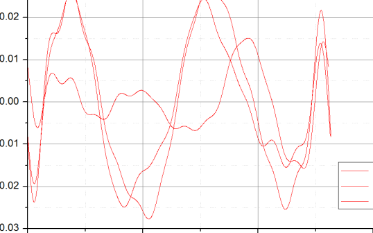
The secondary mirror panels have characteristic sag of a few centimeters and cannot be manufactured by cold slumping technology alone. A two-stage process has been developed to fabricate the secondary mirror panels, mitigating the main technical risk of the pSCT project. First, thin (2 mm) glass foils are pre-shaped to the figure of the highly curved S1 and S2 segments via hot glass slumping replication on a precise low thermal expansion coefficient bending tool. Flabeg, Germany, the developer of this technology, realizes this fabrication step producing glass foils with residual deviations from the ideal figure of-mm amplitude over a mid-scale spatial period of 10-15 cm. Then, the pre-shaped glass foils are assembled into hybrid S1 and S2 panels using the cold slumping method as in M1 panel production. This technology is know to correct large-scale residual deviations; however, it can also achieve mid-scale fine tuning of the panel figure, dramatically reducing such deviations, as can be seen in Figure 1. Both S1 and S2 fine tuning figuring mandrels have been produced at MLT and satisfy specifications. The production of M2 glass foils is completed at Flabeg and their assembly into M2 panels is ongoing at MLT. All M2 panels will be coated by Zaot, Italy.
The metrology data has been encouraging; around half of the S1 panels satisfy specifications of , with the other half just above this target. While the secondary mirror panel production process is still being optimized and improvements are being made, it is nonetheless a success that secondary mirror panels which satisfy the SCT requirements have been produced at an acceptable cost for the implementation of such a telescope design in the context of CTA.
4 Alignment system
4.1 Mirror panel modules


The mirror panels, main component of the P2PAS, are attached to six linear actuators arranged in a Stewart platform (SP) design, with the relative positions between adjacent mirror panels being determined by a collection of mirror panel edge sensors (MPESs). The conjunction of SP and MPES measurements allows for panel-to-panel alignment with an accuracy better than the required 100 . Control of the SP and MPES for each mirror panel, as well as measuring of the external temperature of each SP assembly, is provided by an associated mirror panel controller board (MPCB), mounted to an aluminum triangle which interfaces the mirror panel with the optical support structure (OSS). A mirror panel module (MPM) is defined to be a mirror panel with its accompanying SP, MPES, MPCB, and mounting triangle. A central computer in charge of pSCT alignment controls all 72 MPMs through the MPCBs with a minimal refresh period of measurement and position adjustment of seconds per cycle. A more detailed description of the MPM elements is given in the previous ICRC proceedings [4].
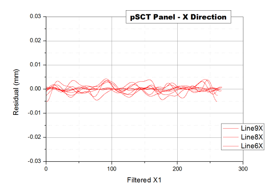
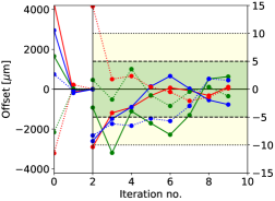
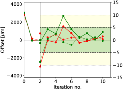
All elements of the MPMs have been assembled, tested, and calibrated. This includes 480 actuators (and accompanying 4 d.o.f. joints, which interface the actuators to the mirror panels and triangles), 80 MPCBs and 380 MPES. The calibration setup for the MPMs has been successfully established at the UCLA Very High Energy (VHE) Laboratory (see Figure 2), where an alignment of under between mirror panels, which translates into an alignment under , has been demonstrated as shown in Figure 3 (left panel).
4.2 Global alignment
The global alignment system measures the relative positions of the pSCT’s primary and secondary mirrors and camera. To make the contribution of global alignment errors negligible in the overall error budget and to meet post calibration pointing specifications, the position of pSCT optical system elements needs to be known with the following accuracy: for the camera center mm ( arcsec on sky) perpendicular to the optical axis (, ), for the camera focal surface along the optical axis () and for the M1 position along the optical axis (). The angular requirements are (, ) ( arcsec on sky). The output of the global alignment system can be fed back into the mirror active control (see Section 4.1) to correct for deformations due to temperature and gravity, with a minimal alignment refresh period of tens of seconds. The alignment system design was driven by the requirement that adjustments will be needed due to significant temperature variations, which cause deformations in the OSS from season-to-season or possibly as frequently as night-to-night. The rigid design of the pSCT mechanical structure is expected to produce only small deformations caused by varying gravitational load which which should not trigger OS re-alignment. The current implementation of the alignment system design can potentially allow for re-alignment of the pSCT optics every run (typically 20-30 minutes). The needed refresh rate of the alignment system will be studied on the pSCT for future corrections in SCT implementation for CTA. We anticipate running the global alignment system continuously to monitor the positions of selected mirror panels every 2 seconds.

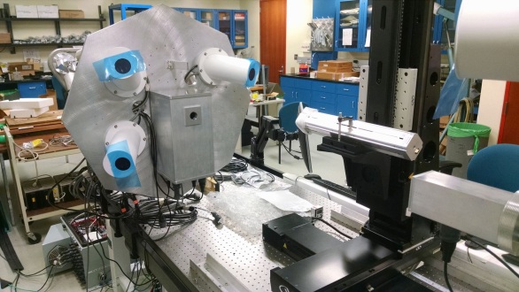
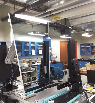
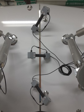
During telescope operation, the global alignment is measured by two different systems: LED / CCD pairs to measure translation and auto-collimator/reflector pairs to measure angular change. Six LEDs are mounted in rectangular patterns on three different panels per mirror and eight LEDs are mounted on an octagon attached to the focal plane of the gamma-ray camera. The CCDs are mounted on two optical tables (OTs) positioned in the centers of M1 and M2 along the telescope’s optical axis, with each CCD having a fixed pointing towards its paired LED targets (7 LED/CCD pairs total). There is one auto-collimator/reflector pair per mirror, also installed on the OTs, and it is pointed at one of the panels also being monitored by a LED/CCD pair. The OTs are central to the global alignment of the telescope. Each OT is made up of a Stewart platform, with an aluminum plate mounted on one end and the other end mounted to the OSS, located on the telescope’s optical axis. The M1 OT houses a laser, and the M2 OT houses a rangefinder, a pair of position sensitive devices (PSDs), and a sky camera. First, the M1 OT is adjusted such that the laser points along the mechanical axis of the telescope. Then the M2 OT is adjusted, using the PSD and rangefinder, such that it moves into the calibrated aligned position with respect to the M1 OT. Once the OTs are aligned, the CCD/LED process can begin to achieve global alignment between M1 and M2. A module containing two PSDs has also been built and calibrated, which can temporarily replace the central camera module and be used to calibrate the camera plane with respect to the optical axis (see Figure 4, right panel).
The OTs are completely assembled, and the calibration procedure for the OTs has been established at UCLA (see Figure 4). This calibration procedure demonstrated the alignment of the laser position on the PSDs to have an accuracy of better than 10 m (for a calibration distance of 2 m), corresponding to an angle below the mrad level on the telescope (see Figure 3 (right panel). During lab testing of prototype LED/CCD equipment using the expected CCD to gamma ray focal plane distance of 1.9 m, we measured a perpendicular accuracy of , and on-axis accuracy of . Using a nominal CCD-to-panel distance of 8.0 m we measured a perpendicular accuracy of , and on-axis accuracy of . The angular accuracy of the auto-collimator/reflector system has a measured angular accuracy of , . The lab tests are all well within tolerances.
4.3 Power and connectivity
The power and connectivity served to all MPMs and OTs are provided by a pair of power and Ethernet distribution boxes (PEDBs), one per mirror, which will be installed onto the telescope M1 and M2 OSS. The PEDBs are equipped with a number of 24 VDC power supplies and 1G Ethernet switches controlled by a low-power ARM computer also operating the environment control (air cooling). Voltages from all power supplies and currents in all SPs are monitored. Both PEDBs have been fully assembled and all ports have been calibrated for voltage and current readings, as well as the internal temperature sensors, and are fully operational.
4.4 Alignment control software
The alignment software performs monitoring of misalignment between MPMs and attempts mirror alignment when necessary. As described in [5], the software is implemented through the OPC-UA communication protocol, following a server-client paradigm, with each MPCB acting as a server of MPES data and actuator control. To allow for failing components and their easy replacement, and extensions of the alignment system in the future, the software addresses hardware components through generic interfaces, retrieving initialization information from a database. This use of generic interfaces also lets us treat global alignment components in the same way as MPMs, feeding coordinate data from CCDs and PSDs into the alignment procedure. The central computer exposes all the necessary alignment data and methods through a top-level OPC-UA server, enabling straightforward integration into CTA’s Array Control.
To be more precise, the alignment software solves a minimization problem, attempting to keep P2PAS and GAS readings at their nominal values. Introducing a panel’s misalignment parameter , where is its misalignment coming from P2PAS readings, comes from global misalignment, and is a weight that effectively forces treating global misalignment more (or less) stringently than panel-to-panel misalignment, this can be written in simplified notation as minimizing
Here, for a given panel , are its positional readings coming from edge sensors (P2PAS) or the global alignment system (GAS); are the actuator displacements that bring it to its nominal position – these are to be solved for; and are the actuator response matrices that connect positional readings with physical motions of actuators. This form highlights the robustness of the alignment system – even with some hardware failing, can still be minimized to a satisfactorily small value. The weight parameter has not been set yet, and will be tuned empirically. The ideal response matrices are identical for all panels, and the real response matrices are only small deviations from this ideal matrix. The response matrices , however, are different for each pair of mirror panels and need to be measured in lab.
The alignment software code of the central computer is multithreaded, collecting sensor data and requesting actuator movements by necessary displacements simultaneously for each individual MPM. This results in the whole mirror aligning nearly as fast as an individual panel.
5 Sunlight and stray light control
A specific feature of the dual-mirror pSCT is the need of the sunlight protection system during day time parking. Such a system has been implemented as a set of baffles, one per mirror, to block most of the sunlight entering the telescope and also being reflected from it. These baffles, along with three different parking positions that alternate throughout the year, provide a safe solution to the sunlight concentration problem as extensively modeled by ray-tracing simulations. In addition, the specific dimensions and arrangement of the baffles have been chosen so to minimize the amount of stray light reaching the gamma-ray camera during normal operations.
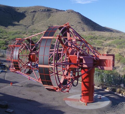
The primary and secondary baffles were constructed in Spring 2016, and were successfully fitted and installed onto the pSCT in Spring 2017 (see Fig. 5).
6 Summary and Outlook
We have presented the current status of the optical system of the prototype Schwarzschild-Couder telescope, currently under construction at the Fred Lawrence Whipple Observatory. All mirror panels for the telescope’s primary mirror have been delivered to UCLA VHE Laboratory. It has been proven that the highly-curved mirror panels for the secondary mirror can be fabricated to meet their corresponding requirements, and production process optimization is underway. Integration tests for the MPMs and OTs have been satisfactorily conducted, and alignment accuracies below m have been consistently achieved. The power and connectivity of all alignment components is guaranteed by the two calibrated PEDBs, and their integrated operation by a mature alignment control software. The sunlight and straylight control elements have been already installed onto the telescope. Integration of the remaining components of the optical system with the telescope structure is expected to begin in July, 2017, with the installation of the OTs. Installation of the mirrors, beginning with the primary, will follow and extend into the early fall, allowing commissioning of the telescope to begin as the summer monsoon season is ending.
7 Acknowledgments
This work was conducted in the context of the SCT project of the CTA Consortium. The project has been made possible by funding provided through the U.S. National Science Foundation Major Research Instrumentation program (MRI award 1229792) and from the agencies and organizations listed here: http://www.cta-observatory.org/consortium_acknowledgments, which we gratefully acknowledge. We particularly recognize the exceptional contributions to the project made by the technical support staff at the Fred Lawrence Whipple Observatory.
References
- [1] V. V. Vassiliev, S. Fegan, and P. Brousseau, Wide field aplanatic two-mirror telescopes for ground-based -ray astronomy, Astroparticle Physics 28 (Sept., 2007) 10–27, [astro-ph/0612718].
- [2] B. Acharya et al., Introducing the CTA concept, Astroparticle Physics 43 (2013), no. 0 3 – 18. [doi.org/10.1016/j.astropartphys.2013.01.007]
- [3] T. Montaruli et al., The small size telescope projects for the Cherenkov Telescope Array, PoS ICRC 2015, 1043 (2016) [arXiv:1508.06472].
- [4] J. Rousselle et al., Construction of a Schwarzschild-Couder telescope as a candidate for the Cherenkov Telescope Array: status of the optical system, PoS ICRC2015 (2016) 938, [arXiv:1509.01143].
- [5] D. Nieto et al., Construction of a medium-sized Schwarzschild-Couder telescope as a candidate for the Cherenkov Telescope Array: development of the optical alignment system, PoS ICRC2015 (2015) 990, [arXiv:1509.02463].
- [6] V. Vassiliev et al., Prototype 9.7m Schwarzschild-Couder telescope for the Cherenkov Telescope Array: Project Overview, Construction and Commissioning Status., PoS ICRC2017 (2017) 838.
- [7] N. Otte et al., Development of a SiPM camera for a Schwarzschild-Couder Cherenkov telescope, PoS ICRC2015 (2015) 1023, [arXiv:1509.02345].
- [8] K. Byrum et al., A Medium Sized Schwarzschild-Couder Cherenkov Telescope Mechanical Design Proposed for the Cherenkov Telescope Array, PoS ICRC2015 (2015) 1029, [arXiv:1509.03074].