Perfect Anomalous Reflection with a Binary Huygens’ Metasurface
Abstract
In this paper we propose a new metasurface that is able to reflect a known incoming electromagnetic wave into an arbitrary direction, with perfect power efficiency. This seemingly simple task, which we hereafter call perfect anomalous reflection, is actually highly non-trivial due to the differing wave impedances and complex interference between the incident and reflected waves. Heretofore, proposed metasurfaces which achieve perfect anomalous reflection require complicated, deeply subwavelength and/or multilayer element structures which allow them to couple to and from leaky and/or evanescent waves. In contrast, we demonstrate that using a Binary Huygens’ Metasurface (BHM) — a passive and lossless metasurface with only two cells per period — perfect anomalous reflection can be achieved over a wide angular and frequency range. Through simulations and experiments at 24 GHz, we show that a properly designed BHM can anomalously reflect an incident electromagnetic wave from to , with perfect power efficiency to within experimental precision.
I Introduction
The ability to direct the flow of electromagnetic waves at will has captured the fascination of scientists and engineers. Potential applications include scientific and medical imaging, information and communication technology, and energy harvesting among many others. The recent decades have witnessed the emergence of metamaterials and metasurfaces which provide designer-defined properties to direct electromagnetic waves in arbitrary manner Veselago (1968); Pendry (2000); Shelby et al. (2001); Eleftheriades et al. (2002); Fang et al. (2005); Alù and Engheta (2005); Pendry et al. (2006); Jacob et al. (2006); Silveirinha and Engheta (2006); Smolyaninov et al. (2007); Landy et al. (2008); Gharghi et al. (2011); Sievenpiper et al. (1999); Holloway et al. (2005); Yu et al. (2011); Maci et al. (2011); Holloway et al. (2012); Pfeiffer and Grbic (2013); Selvanayagam and Eleftheriades (2013); Kim et al. (2014); Lin et al. (2014). Specifically, a phase-gradient metasurface has been heavily investigated as a ubiquitous tool to control the reflection and transmission of a known incident wave Yu et al. (2011); Lin et al. (2014). More recently, the Huygens’ metasurface — a surface which provides both electric and magnetic responses to an incoming EM wave — has garnered attention as a metasurface with ultimate wave manipulation capabilities Pfeiffer and Grbic (2013); Selvanayagam and Eleftheriades (2013); Wong et al. (2014); Kim et al. (2014); Selvanayagam and Eleftheriades (2014); Epstein et al. (2016). For instance, it has been shown that total transmission and redirection of an incident wave is possible with a passive bianisotropic Huygens’ metasurface, implementable on three closely-spaced layers of reactive elements Wong et al. (2016).
The problem of arbitrarily reflecting an electromagnetic wave, however, has proven surprisingly tricky. Prior to works on metasurfaces, researchers studying blazed gratings — gratings which perform efficient retroreflection — found that some thick gratings could redirect a wave into directions other than retroreflection with very high efficiency. These so-called “off-Bragg” gratings were numerically demonstrated for small to moderate separation angles Jull and Beaulieu (1979); Cho et al. (1997); Chen et al. (2013). A theoretical investigation Maystre and Cadilhac (1981) found, from the perspective of plane wave diffraction, that perfect anomalous reflection was possible given the successful achievement of two angular parameters. The extent to which these parameters can be tuned remained unclear, but the authors of Maystre and Cadilhac (1981) further showed that for specific incidence and diffracted angles, the required parameters can be achieved by tuning the groove depth of a rectangular groove grating. However, recent works on metasurfaces Asadchy et al. (2016); Estakhri and Alù (2016); Epstein and Eleftheriades (2016) considered the electromagnetic waves at an impedance boundary, and showed that, in order to steer an incident wave into an “anomalous” direction with perfect efficiency, one needs a reflection surface which is lossy (absorbs the incident wave) in some areas and active (reradiates more power than in the incident wave) in other areas. This finding raises questions on how a passive structure, like a grating, can achieve perfect anomalous reflection. Further, this explains why phase-gradient metasurfaces Yu et al. (2011) and some Huygens’ metasurfaces Pfeiffer and Grbic (2013); Selvanayagam and Eleftheriades (2013) failed to achieve perfect anomalous reflection, but instead generated undesirable spurious reflection and/or transmission components.
Several alternatives have thus been proposed to achieve anomalous reflection. Ref. Kim et al. (2014) first reported the reduction of spurious reflection in a metasurface with an appropriately designed loss profile. Later, refs. Asadchy et al. (2016); Estakhri and Alù (2016) showed that for the plane wave reflection case, one can completely eliminate spurious components by including loss in a passive metasurface. This allows one to achieve anomalous reflection at an efficiency limited by impedance mismatch, given by
| (1) |
Alternatively, more power can be anomalously transmitted if one also allows some of the incident wave to be scattered into other directions. However, in both these cases, impedance mismatch makes it impossible to efficiently redirect a wave to or from near-grazing angles. More recently, refs. Epstein and Eleftheriades (2016); Díaz-Rubio et al. (2017); Asadchy et al. (2017) proposed specialized metasurfaces which redistribute power along the surface using auxiliary evanescent waves Epstein and Eleftheriades (2016) or leaky waves Díaz-Rubio et al. (2017); Asadchy et al. (2017), to achieve the aforementioned absorptive and radiation regions using a passive and lossless metasurface. However, in these cases, the respective authors have not suggested a straightforward process through which one can design physical metasurface structures capable of achieving the aforementioned power transfer or auxiliary wave generation. Furthermore, the proposed metasurfaces are conceptually complex, in that they require very intricate coupling mechanisms, deeply subwavelength element dimensions and intricate metallization patterns and/or multilayer bianisotropic metasurface elements Epstein and Eleftheriades (2016); Díaz-Rubio et al. (2017); Asadchy et al. (2017).
In this paper we report a very simple metasurface that successfully facilitates the aforementioned power redistribution and achieves perfect anomalous reflection, without any explicit involvement of surface or leaky waves. We show that maximally discretized metasurfaces — with as few as two simple elements per period — can be built to reflect an electromagnetic wave from a given input direction to a desired output direction. As an example, we demonstrate perfect anomalous reflection from an incident direction to a reflection direction using a Binary Huygens’ Metasurface (BHM) — a Huygens’ metasurface with only two elements per period. Experimental results corroborate with simulation to show near-perfect power transfer from the incident to the desired reflection direction, and show that efficient reflection of greater than power transfer from the incident to the redirected wave can be achieved over a wide bandwidth of . Our results demonstrate that such perfect anomalous reflection can be achieved without resorting to intricate, active or lossy metasurface profiles, and that this realization leads to superior metasurfaces capable of broadband performance. Furthermore, the development in this paper reconciles current works on metasurfaces with previous results in dielectric and metallic gratings: it offers a plausible explanation to the fundamental electromagnetics behind previous studies of near-perfect anomalous reflection from off-Bragg gratings.
II Results
II.1 Aggressive Metasurface Discretization
We begin by describing our theoretical results regarding the discretization of a general periodic metasurface, which includes but is not limited to a perfect anomalous reflector. The common method for metasurface design is to design a continuous impedance/admittance surface which satisfies the interface boundary condition between a given and a desired electromagnetic wave. Thereafter, the surface is finely discretized and implemented using metasurface elements with corresponding electromagnetic properties. Typical metasurface discretizations range from 8 to 12 cells per wavelength (or in some cases per period) Smith et al. (2011); Pfeiffer and Grbic (2013); Epstein et al. (2016). These discretizations are usually verified to be of sufficiently fine granularity by yielding results which approximate the theoretical or simulated performance of the continuous counterpart. However, we propose to investigate and implement a metasurface that is as aggressively discretized as possible in regards to the number of elements per period. We shall show that an aggressively discretized metasurface will lead to simple, robust and broadband metasurface implementation. Also, we shall show that the aggressively discretized metasurface has a counterintuitive effect of allowing possibilities unattainable by its continuous counterpart, which, in the case of this paper, enables it to achieve perfect anomalous reflection without explicitly involving a transfer of power through surface or leaky waves.
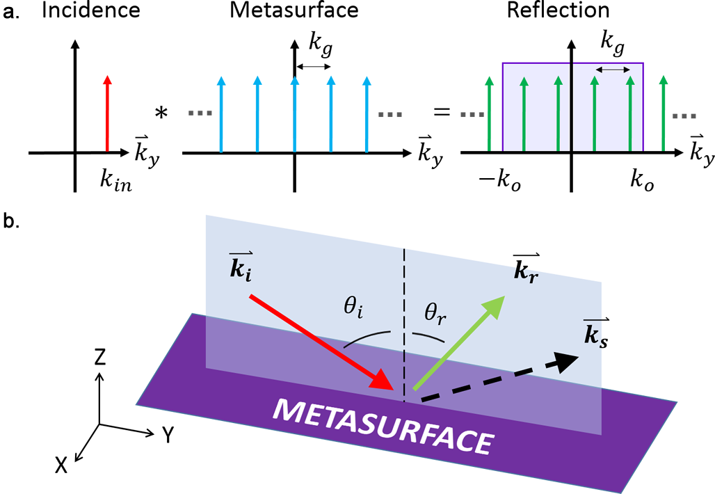
We employ a diffraction-based perspective to investigate sufficient discretization of a periodic metasurface Wong et al. (2017). Fig. 1a shows the -space operation of a metasurface with period and period . Upon the incidence of a plane wave, the periodic metasurface reflects multiple diffraction orders depicted by the location of the arrows. The amplitude and phase of the diffraction orders are dependent on the reflective properties of the metasurface. It is instructive to note that, while an infinite number of diffraction orders exist in -space, only a finite number of diffraction orders fall within the propagation range of . These represent plane waves that scatter into the far-field, with the propagation angle given by
| (2) |
The other diffraction orders represent evanescent waves that remain within the near-field of the metasurface, but do not contribute to the far-field reflection pattern. The number of outgoing diffraction modes is given by
| (3) |
We show in the supplemental material that a metasurface with independent degrees of freedom is sufficient for tuning the reflection dynamics into each propagation diffraction order. Further, we show that these degrees of freedom can be met by regenerating the electromagnetic fields at sample points, equidistant along the length of the period, using an array of Huygens’ sources.
It is of interest to note that, for a class of metasurfaces with sufficiently large spatial frequency such that , there exists only two propagating diffraction orders. This condition is satisfied by many metasurfaces: for example, in retroreflection metasurfaces with Hessel et al. (1975); Memarian et al. (2017); Wong et al. (2017). We shall show in the next sub-section that this also is the case for many perfect anomalous reflectors. For these cases, the metasurface can be aggressively discretized to having only two elements per grating period Wong et al. (2017). We name the resultant surface a Binary Huygens’ Metasurface (BHM). In a previous work we have designed a BHM to perform near-grazing angle retroreflection Wong et al. (2017). We shall proceed to show that a properly designed BHM can also perform perfect anomalous reflection across a wide range of frequencies.
II.2 Perfect Anomalous Reflector: Design and Simulation
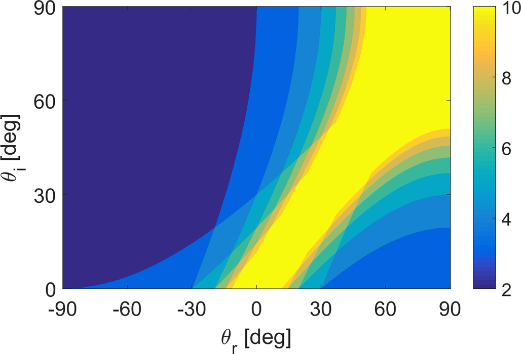
We now concentrate our discussion on a perfect anomalous reflection metasurface. A schematic of a perfect anomalous reflector is shown in Fig. 1b. The surface accepts an incident wave at and anomalously reflects it at an anomalous reflection angle . Specular reflection () is totally suppressed. To construct an aggressively discretized perfect anomalous reflection metasurface, one can choose the metasurface period such that . Substituting this into (3) yields
| (4) |
Fig. 2 plots this relationship for and . The sizeable region shaded in dark blue () on the left side of the plot indicates the region for which there exists only two propagating diffraction orders. Hence a binary Huygens’ metasurface suffices to perfectly redirect the incident power from the incident to the anomalous reflection angle. Hence for the remaining regions , more metasurface elements are needed for every period. The yellow region () denotes sets of for which many (ten or more) elements are needed. However, this region also represents ‘weak’ anomalous reflection, in the sense that the reflection angle is only slightly deviated from the incident angle (). Therefore, the period is also correspondingly large, which allows the elements to be spaciously spaced despite the need for many elements within one period.
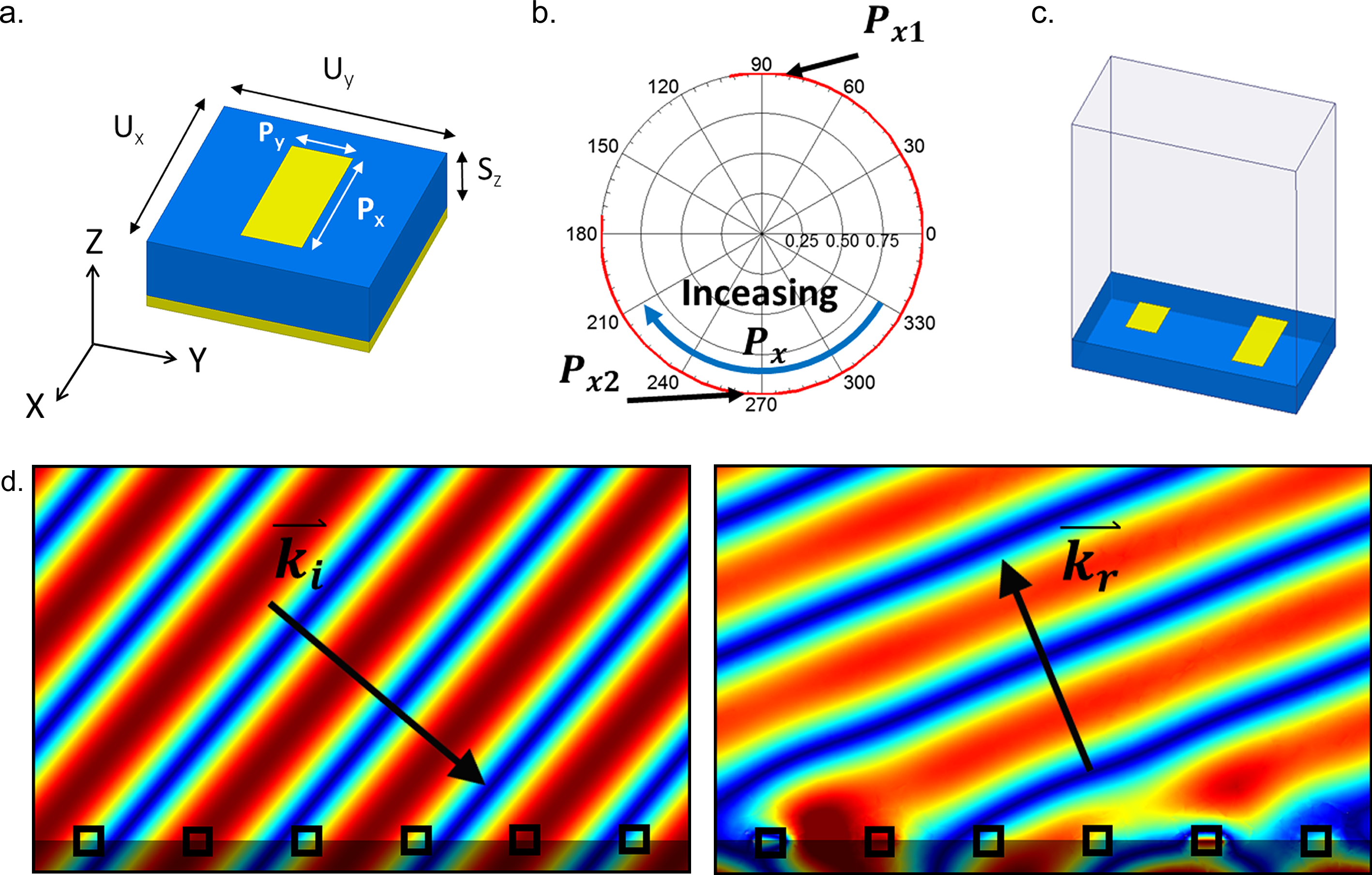
As a design example demonstrating the Binary Huygens’ metasurface, we design our metasurface for the microwave regime at a frequency of 24 GHz. We construct the metasurface on a printed circuit board (PCB) with 1.575 mm thickness and a permittivity of . We choose as the metasurface element the ground-backed dipole, which, as we have shown in previous works Kim et al. (2014); Wong et al. (2017, 2017), can operate as an efficient Huygens’ metasurface component. This also exhibits various desirable properties such as low loss, effective phase tuning and a reasonably large tolerance to bandwidth and angular variations. A schematic of the unit cell is shown in Fig. 3a. We seek to design a metasurface that performs perfect anomalous reflection to convert a TE wave from an incident angle of to an anomalously reflected angle of . A substitution into (4) shows that there are only two propagation modes for a metasurface with this periodicity. Hence a Binary Huygens’ Metasurface can achieve perfect anomalous reflection into the required direction.
We describe our design process and report full-wave electromagnetic simulation results using the commercial simulator Ansys HFSS. We first characterize the reflection properties of a single element when placed in an infinitely periodic array in the - and - directions. This is achieved by a full-wave Floquet (periodic) simulation. An electromagnetic plane wave, with electric field pointing in the -direction, impinges the element at , and specular reflection is measured. Fig. 3b shows the variation in specular reflection as we vary the dipole length . We observe that we achieve a near-unity reflection magnitude throughout the sweep, while the reflection phase differs by about at the operation points mm and mm. As in Wong et al. (2017), we combine elements which exhibit difference in phase behaviour to suppress specular reflection and thereby efficiently redirect an incoming wave towards the desired anomalous reflection.
We hence combine the aforementioned elements to form the BHM. When these metasurface elements are placed adjacent to each other, their mutual coupling dynamics cause slight deviations in their reflection properties, which in turn degrade the suppression of specular reflection. To account for this, we sweep from 3.4 mm to 3.8 mm in this new environment, and find that at mm, we reestablish destructive interference in the specular direction, and thereby optimize power transfer to the anomalous direction. The resultant Floquet simulation shows that this BHM transfers of the incident power from to ; of the power remains as specular reflection. This demonstrates “perfect” anomalous reflection to within the accuracy of the simulation, and certainly exceeds the power transfer efficiency as dictated by the impedance mismatch relationship (1).
Fig. 3d shows the incident and scattered waves obtained from the simulation; animations showing the phase progression of both waves are available in the supplemental material that accompanies this paper SM2 . Both the figure and the animations show that the incident wave is reflected anomalously in a near-perfect manner. In accordance to electromagnetic theory, in a scenario of perfect power transfer from the incident wave into anomalous reflection, the reflected wave features an electric field that differs in amplitude from the incident wave:
| (5) |
Notwithstanding this lower field amplitude, perfect power transfer is achieved because the anomalously reflected wave carries power more efficiently in the -direction.
II.3 Power Flow Analysis
Fig. 4 examines the power flow dynamics of the BHM. The top panel of the figure shows the geometry of the metasurface, while the middle three panels show the -directed Poynting vector (electromagnetic power flow) across three planes, at distances , and above the metasurface. implies that power is radiated by the metasurface; conversely, implies that power is absorbed. In close proximity to the metasurface (), we see that the power flow forms an intricate pattern due to the reactive near-field. However, as increases, the evanescent field diminishes and approaches a sinusoid. The bottom panel plots the variation at and (red, solid). It shows that this variation very well approximates the theoretical sinusoidal variation (blue, dotted) of a perfect anomalous reflection metasurface Asadchy et al. (2016); Estakhri and Alù (2016)
| (6) |
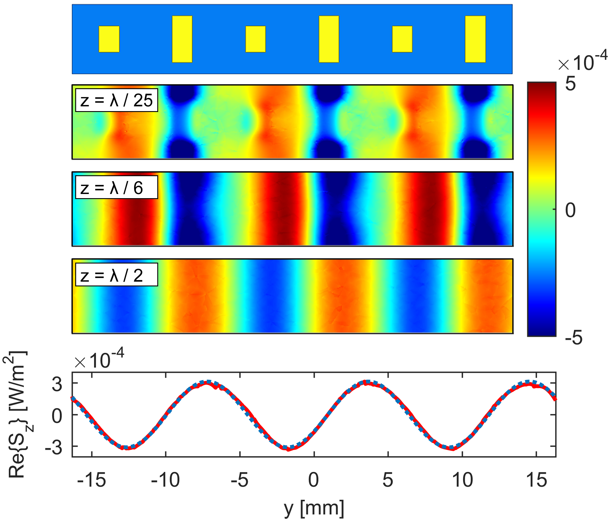
where is the free-space wave impedance and is a constant reflection phase offset. It was previously noted that perfect anomalous reflection required a redistribution of power, such that half the surface is active () and the other half is lossy (). We have hereby shown that, notwithstanding its apparent simplicity, the BHM successfully accomplishes this necessary redistribution of power through aggressive discretization and the consideration of diffraction modes. We find that this process involves evanescent waves as in Epstein and Eleftheriades (2016), but in an implicit manner which simplifies rather than complicates the task of metasurface design and construction.
II.4 Finite Surface and Bandwidth Analysis
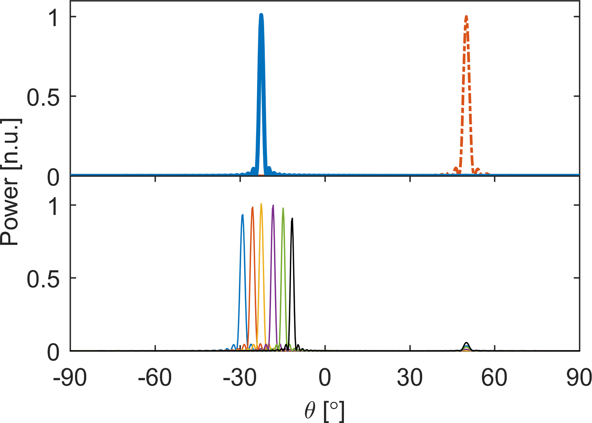
We proceed to simulate the reflection properties of the metasurface when it is truncated to a finite size of 78 cells (413.4 mm) in the -direction. Fig. 5 (top panel) shows the reflection characteristics under a 24 GHz plane wave illumination at the designed incident angle. Specular reflection is suppressed to 30 dB (1000 times) below the anomalous reflection power, hence most of the power is anomalously reflected to the desired direction of . To obtain a measurement of power efficiency, the peak of the scattered wave is normalized to the geometric mean of simulated specular reflections for and for a perfect conductor of the same size as the metasurface. (We refer the interest reader to the supplemental material for detailed explanation on our normalization procedure SM1 . Hence a peak magnitude of 0.03 dB (or ) conveys that the finite-sized metasurface has achieved perfect anomalous reflection to within the accuracy of the simulation.
To illustrate the broadband performance of the metasurface, Fig. 5 (bottom panel) shows the reflection characteristics for a range of frequencies from 22 to 28.5 GHz. Due to the non-resonant nature of the metasurface element, the specular reflection remains significantly suppressed throughout this bandwidth, thus enabling the metasurface to achieve anomalous reflection at a very high () efficiency over this bandwidth. Beam squinting — the variation in beam angle with respect to frequency Mailloux (2005) — is observed in accordance to antenna array theory. While perfect anomalous reflection is demonstrated at the design frequency, a high-efficiency anomalous reflection of over and significant improvement over the limitation of impedance mismatch is also achieved over this very large fractional bandwidth of .
II.5 Experimental Demonstration
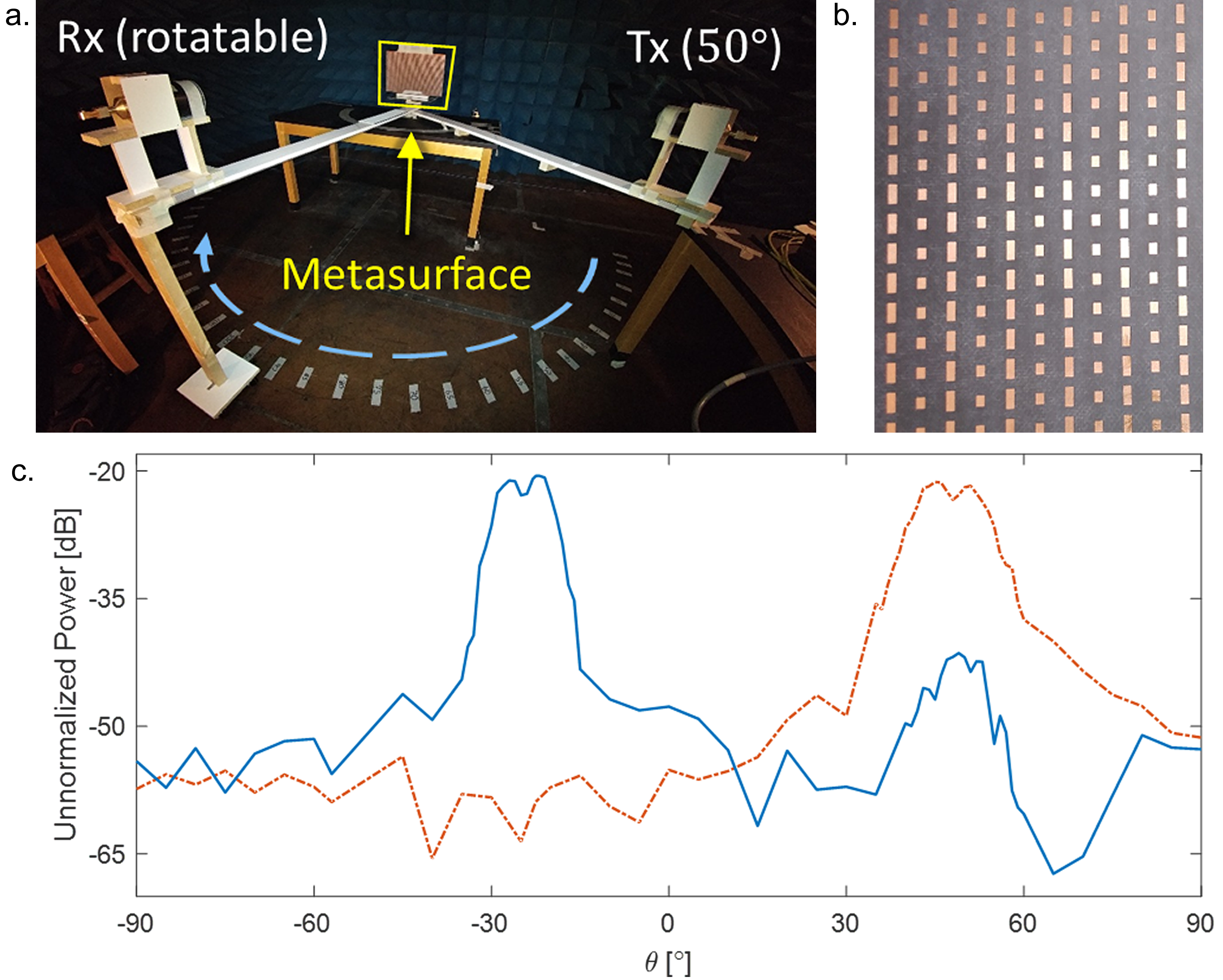
We fabricated and experimentally measured anomalous reflection from the Binary Huygens’ metasurface. We fabricated the BHM on a Rogers RT/Duroid 5880 laminate board, with 1.575 mm thickness and plated with 1 oz. (35.6 m) copper on both sides. The substrate has a permittivity of (as in the simulation) and a low dissipation factor of . Figs. 6a and 6b show the fabricated metasurface and the experimental apparatus. A K-band lens antenna emits a vertically- (-) polarized Gaussian beam at , about 1.5 m from the test surface. A second lens antenna receives the scattered signal, and is swept across the -plane to measure the test surface’s angular scattering profile. To calibrate the system, we first measure the specular reflection strengths of an aluminum test plate with the same size as the Binary Huygens’ Metasurface. We find that the power reflected from the aluminum plate at and differ by about 0.5 dB — which is within the expected error of the experimental apparatus. This implies that the incident Gaussian beam is concentrated at the center of the test surface, such that the power loss due to spillover was negligible. Hence the strength of the anomalous reflection can be found through direct comparison to specular reflection strength for . Fig. 6c compares the scattering pattern of the BHM (blue, solid) to that of the metallic test plate (red, dashdot). We observe that the angular spread of the Gaussian beam broadens the reflection features (both by the metallic plate and by the BHM) to a 3 dB (half-power) width of around . Notwithstanding, it is clear that the anomalous reflection surface suppresses specular reflection by about 20 dB, and achieves perfect anomalous reflection to within the sensitivity of the experimental apparatus.
III Conclusion
In this paper we have shown that perfect anomalous reflection is possible with an aggressively discretized metasurface. In particular, we demonstrated that a Binary Huygens’ Metasurface, built from ground-backed electric dipoles, can steer an incoming electromagnetic wave at to a reflection angle , with perfect efficiency to within the tolerance of full-wave simulation and experimental measurement. In departure to previous proposals, the proposed BHM is surprisingly simple in its single layer structure and large and simple element sizes, which bodes well to the BHM’s practical fabrication even at higher frequencies, such as mm-wave, terahertz and beyond. Further, we demonstrate that due to the non-resonant nature of the elements involved, the reported BHM attains wideband performance: though the BHM was designed for operation at 24 GHz, anomalous reflection with greater than efficiency was demonstrated from 22 GHz to 28.5 GHz. Examining the power flow normal to the metasurface reveals that the discretized metasurface implicitly invokes the necessary evanescent waves which facilitate power redistribution from one part of the metasurface to another, as found necessary in Asadchy et al. (2016); Estakhri and Alù (2016). This implicit involvement of evanescent waves may also have been the operation mechanism through which traditional anomalous reflection gratings achieved the power redistribution along the reflection surface. In this perspective, the present work reconciles earlier observations of seemingly efficient anomalous reflection in gratings with recent developments in electromagnetic metasurfaces.
During the preparation of this paper, a work Ra’di et al. (2017) on ‘meta-gratings’ has come to our attention, which also takes the perspective of diffraction modes to achieve high-efficiency wavefront steering. While the aforementioned work numerically investigated wavefront steering using complex single grating elements, the present paper investigates, through both full-wave simulation and experiment, wavefront design with multiple (two or more) simple elements, distributed within a single period of the metasurface. Further, in this work the usage of non-resonant metasurface elements has led to the experimental demonstration of broadband anomalous reflection beyond what has been reported by previous works.
References
- Veselago (1968) V. G. Veselago, Soviet Physics Uspekhi 10, 509 (1968).
- Pendry (2000) J. B. Pendry, Phys. Rev. Lett. 85, 3966 (2000).
- Shelby et al. (2001) R. A. Shelby, D. R. Smith, and S. Schultz, Science 292, 77 (2001).
- Eleftheriades et al. (2002) G. V. Eleftheriades, A. K. Iyer, and P. C. Kremer, IEEE Trans. Microw. Theory Techn. 50, 2702 (2002).
- Fang et al. (2005) N. Fang, H. Lee, C. Sun, and X. Zhang, Science 308, 534 (2005).
- Alù and Engheta (2005) A. Alù and N. Engheta, Phys. Rev. E 72, 016623 (2005).
- Pendry et al. (2006) J. B. Pendry, D. Schurig, and D. R. Smith, Science 312, 1780 (2006).
- Jacob et al. (2006) Z. Jacob, L. V. Alekseyev, and E. Narimanov, Opt. Express 14, 8247 (2006).
- Silveirinha and Engheta (2006) M. Silveirinha and N. Engheta, Phys. Rev. Lett. 97, 157403 (2006).
- Smolyaninov et al. (2007) I. I. Smolyaninov, Y. J. Hung, and C. C. Davis, Science 315, 1699 (2007).
- Landy et al. (2008) N. I. Landy, S. Sajuyigbe, J. J. Mock, D. R. Smith, and W. J. Padilla, Phys. Rev. Lett. 100, 207402 (2008).
- Gharghi et al. (2011) M. Gharghi, C. Gladden, T. Zentgraf, Y. Liu, X. Yin, J. Valentine, and X. Zhang, Nano Lett. 11, 2825 (2011).
- Sievenpiper et al. (1999) D. Sievenpiper, L. Zhang, R. F. J. Broas, N. G. Alexopolous, and E. Yablonovitch, IEEE Trans. Microw. Theory Techn. 47, 2059 (1999).
- Holloway et al. (2005) C. L. Holloway, M. A. Mohamed, E. F. Kuester, and A. Dienstfrey, IEEE Trans. Electromagn. Compat. 47, 853 (2005).
- Yu et al. (2011) N. Yu, P. Genevet, M. A. Kats., F. Aieta, J. Tetienne, F. Capasso, and Z. Gaburro, Science 334, 333 (2011).
- Maci et al. (2011) S. Maci, G. Minatti, M. Casaletti, and M. Bosiljevac, IEEE Antennas Wireless Propag. Lett. 10, 1499 (2011).
- Holloway et al. (2012) C. L. Holloway, E. F. Kuester, J. A. Gordon, J. O’Hara, J. Booth, and D. R. Smith, IEEE Antennas and Propagation Magazine 54, 10 (2012).
- Pfeiffer and Grbic (2013) C. Pfeiffer and A. Grbic, Phys. Rev. Lett. 110, 197401 (2013).
- Selvanayagam and Eleftheriades (2013) M. Selvanayagam and G. V. Eleftheriades, Opt. Express 21, 14409 (2013).
- Kim et al. (2014) M. Kim, A. M. H. Wong, and G. V. Eleftheriades, Phys. Rev. X 4, 041042 (2014).
- Lin et al. (2014) D. Lin, P. Fan, E. Hasman, and M. L. Brongersma, Science 345, 298 (2014).
- Wong et al. (2014) J. P. S. Wong, M. Selvanayagam, and G. V. Eleftheriades, Photonics Nanostruct. Fundam. Appl. 12, 360 (2014).
- Selvanayagam and Eleftheriades (2014) M. Selvanayagam and G. V. Eleftheriades, IEEE Trans. Antennas Propag. 62, 6155 (2014).
- Epstein et al. (2016) A. Epstein, J. P. S. Wong, and G. V. Eleftheriades, Nat. Commun. 7, 10360 (2016).
- Wong et al. (2016) J. P. S. Wong, A. Epstein, and G. V. Eleftheriades, IEEE Antennas Propag. Lett. 15, 1293 (2016).
- Jull and Beaulieu (1979) E. V. Jull and N. C. Beaulieu, IEEE AP-S Int. Sym. Dig. , 515 (1979).
- Cho et al. (1997) Y. K. Cho, J. W. Ra, U. H. Cho, and J. I. Lee, Electron. Lett. 33, 1446 (1997).
- Chen et al. (2013) W. Chen, N. C. Beaulieu, D. G. Michelson, and E. V. Jull, IEEE Trans. Antennas Propag. 61, 2342 (2013).
- Maystre and Cadilhac (1981) D. Maystre and M. Cadilhac, Radio Sci. 16, 1003 (1981).
- Asadchy et al. (2016) V. S. Asadchy, M. Albooyeh, S. N. Tcvetkova, A. Díaz-Rubio, Y. Ra’di, and S. A. Tretyakov, Phys. Rev. B 94, 075142 (2016).
- Estakhri and Alù (2016) N. M. Estakhri and A. Alù, Phys. Rev. X 6, 041008 (2016).
- Epstein and Eleftheriades (2016) A. Epstein and G. V. Eleftheriades, Phys. Rev. Lett. 117, 256103 (2016).
- Díaz-Rubio et al. (2017) A. Díaz-Rubio, V. Asadchy, A. Elsakka, and S. Tretyakov, Sci. Advanced. 3, e1602714 (2017).
- Asadchy et al. (2017) V. S. Asadchy, A. Wickberg, A. Díaz-Rubio, and M. Wegener, ACS Photonics 4, 1264 (2017).
- Smith et al. (2011) D. R. Smith, Y. Tsai, and S. Larouche, IEEE Antennas Wireless Propag. Lett. 10, 1605 (2011).
- (36) See Supplemental Material at [URL will be inserted by publisher] for (1) a derivation on the maximum allowable discretization in a metasurface and (2) the normalization procedure for power efficiency analysis for an anomalous reflection metasurface.
- Wong et al. (2017) A. M. H. Wong, and G. V. Eleftheriades, General Assembly and Scientific Symposium (USNC-URSI GASS), 2017 United States National Committee of URSI National arXiv:1706.02765 (2017).
- Hessel et al. (1975) A. Hessel, J. Schmoys, and D. Y. Tseng, J. Opt. Soc. Am. 65, 380 (1975).
- Memarian et al. (2017) M. Memarian, X. Li, Y. Morimoto, and T. Itoh, Sci. Rep. 7, 42286 (2017).
- Wong et al. (2017) A. M. H. Wong, P. Christian, and G. V. Eleftheriades, Radio Science Meeting (USNC-URSI NRSM), 2017 United States National Committee of URSI National (2017).
- (41) See Supplemental Material at [URL will be inserted by publisher] for animations of the waves incident to and reflected from the Binary Huygens’ Metasurface.
- Mailloux (2005) R. J. Mailloux, Phased array antenna handbook, 2nd ed. (Artech House, Boston, 2005).
- Ra’di et al. (2017) Y. Ra’di, D. L. Sounas, and A. Alù, Phys. Rev. Lett. 119, 067404 (2017).