GReEneR: A Tool for Improving Energy Efficiency of Register Files
Abstract.
Graphics Processing Units (GPUs) maintain a large register file to increase the thread level parallelism (TLP). To increase the TLP further, recent GPUs have increased the number of on-chip registers in every generation. However, with the increase in the register file size, the leakage power increases. Also, with the technology advances, the leakage power component has increased and has become an important consideration for the manufacturing process. The leakage power of a register file can be reduced by turning infrequently used registers into low power (drowsy or off) state after accessing them. A major challenge in doing so is the lack of runtime register access information.
This paper proposes GReEneR (Gpu REgister file ENErgy Reducer): a system to minimize leakage energy of the register file of GPUs. GReEneR employs a compile-time analysis to estimate the run-time register access information. The result of the analysis is used to determine the power state of the registers (ON, SLEEP, or OFF) after each instruction. We propose a power optimized assembly instruction set that allows GReEneR to encode the power state of the registers in the executable itself. The modified assembly, along with a run-time optimization to update the power state of a register during execution, results in significant power reduction.
We implemented GReEneR in GPGPU-Sim simulator, and used GPUWattch framework to measure the register file’s leakage power. Evaluation of GReEneR on 21 kernels from CUDASDK, GPGPU-SIM, Parboil, and Rodinia benchmarks suites shows an average reduction of register leakage energy by 69.04% and maximum reduction of 87.95% with a negligible number of simulation cycles overhead (0.53% on average).
1. Introduction
Graphics Processing Unit (GPU) achieves high throughput by utilizing thread level parallelism (TLP). Typically, GPUs maintain a large register file in each streaming multiprocessor (SM) to improve the TLP. GPUs allow a large number of resident threads (Kepler, 2012) in each SM, and the resident threads can store their thread context in the register file, which facilitates faster context switching of the threads. The threads that are launched in each SM are grouped into sets of 32 threads (called warps), and they execute the instructions in a single instruction, multiple threaded (SIMT) manner. To keep improving the TLP of the GPUs, GPU architects increase the maximum number of resident threads and register file sizes in every generation. For instance, NVIDIA Fermi GF100 has 128KB register file and allows up to 1536 resident threads, while NVIDIA Kepler GK110 has 256KB register file and allows maximum 2048 resident threads (Kepler, 2012).
Earlier studies (Leng et al., 2013; Jeon et al., 2015) show that register files in GPUs consume around 15% of the total power. With the technology advances, the leakage power component has increased and has become an important consideration for the manufacturing process (Kim et al., 2003). Moreover, registers in a GPU continue to dissipate leakage power throughout the entire execution of its warp even when they are not accessed by the warp.
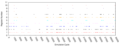
Each data point shows the access of a register (Y-axis) during a cycle (X-axis).
1.1. Motivation
To understand the severity of leakage power dissipation by register file, consider Figure 1 which shows the access patterns of some registers of warp 0 during the execution of MUM application (The experimental methodology has been discussed in Section 4). We use the access patterns of the registers of a single warp as a representative since all the warps of a kernel typically show similar behavior during execution (Abdel-Majeed et al., 2017). We make the following observations:
-
•
Register 10 is accessed very infrequently—it is accessed for only 7 cycles during the complete execution (life time) of the warp (29614 cycles).
-
•
Register 1 is the most frequently accessed register during the warp execution. However, it is accessed for only 330 cycles ( 1.11%) during the life time of the warp.
This shows that registers are accessed for a very short duration during the warp life time. However, they continue to dissipate leakage power for the entire life time of the warp. Figure 2 shows that the behavior is not specific to MUM, but is seen across a wide range of applications. The figure shows the percentage of simulation cycles spent in register accesses (averaged over all the registers in all the warps) for several applications. We observe that registers on an average spend of the simulation cycles during the warp execution while leaking power during the entire execution.
One solution (Abdel-Majeed and Annavaram, 2013) to reduce the leakage power of the registers is by putting the registers into drowsy or SLEEP111Drowsy (Abdel-Majeed and Annavaram, 2013; Flautner et al., 2002) and SLEEP (Li et al., 2013) states refer to the same low power data preserving states. In this paper, we use the term SLEEP. state immediately after the registers of an instruction are accessed. However, this can have run-time overhead whenever there are frequent wake up signals to the sleeping register. Consider Figure 1 again:
-
•
Putting register 10 to SLEEP state immediately after its accesses saves significant power due to the gaps of several thousands of cycles between consecutive accesses.
-
•
In contrast, register 1 is accessed very frequently. If it is put to SLEEP after every access, it will have a high overhead of wake up signals.
-
•
The access pattern of register 7 changes during the warp execution. It is accessed frequently for some duration (for example, between cycles 10500–11250), and not accessed frequently for other duration (between cycles 3000–7500). To optimize energy as well as run-time, the register needs to be kept ON whenever it is frequently accessed, and put to SLEEP otherwise.
-
•
The last access to register 8 is at cycle 1602. The register can be turned OFF after its last access to save more power.
In summary, the knowledge of registers’ access patterns helps improve energy efficiency without impacting the run-time adversely. Our proposed solution GReEneR statically estimates the run-time usage patterns of registers to reduce GPU register file leakage power.

1.2. Contributions
GReEneR uses a compile-time analysis to determine the power state of the registers (OFF, SLEEP, or ON) for each instruction by estimating the register usage information. Further, it transforms an input assembly language by encoding the power state information at each instruction to make it energy efficient. The static analysis makes safe approximations while computing power state of the registers, therefore, the choice of the state can be suboptimal at run-time. Hence, to improve the accuracy and energy efficiency, it provides a run-time optimization that dynamically corrects the power state of registers of each instruction. We make the following contributions:
-
(1)
We introduce a new instruction format that supports the power states for the instruction registers (Section 3.2). We propose a compile-time analysis that determines the power state of the registers at each program point and transforms an input assembly language into a power optimized assembly language (Section 3.1 and 3.2).
-
(2)
We propose a run-time optimization to reduce the penalty of suboptimal (but safe) choices made by static analysis (Section 3.3).
- (3)
-
(4)
We evaluated our implementation on wide range of kernels from different benchmark suites: CUDASDK (CUDA-SDK, 2014), GPGPU-SIM (Bakhoda et al., 2009), Parboil (Parboil, 2012), and Rodinia (Che et al., 2009). We observe a reduction in the register leakage energy by an average of 69.04% and maximum of 87.95% (Section 4).
2. Background
GPUs consist of a set of streaming multiprocessors (SMs). Each SM contains a large number of execution units such as ALUs, SPs, SFUs, and Load/Store units. GPUs achieve high throughput because they can hide long memory execution latencies with massive thread level parallelism. Each SM has a large register file, which allows the resident threads to maintain their contexts, and hence can have faster context switching. To reduce the access latency, the register file is divided into multiple banks. The registers from different banks can be accessed in parallel. A bank conflict occurs whenever multiple registers need to be accessed from the same bank, and these need to be accessed in serial. In GPGPU-Sim simulator (GPGPUSIM, 2014) the requests for instruction registers are stored in a collector unit. When all the operands of the instruction are ready, it can proceed to the execution stage.
NVIDIA provides a programming language CUDA (CUDA, 2012) to parallelize applications on GPU. The portion of the code which is to be parallelized is specified using a special function called kernel. A kernel is invoked with the number of thread blocks and the number of threads in each thread block as parameters. A program written in CUDA can be compiled using nvcc compiler. The compiler translates the program into an intermediate representation (PTX), which is finally translated to an executable code. NVIDIA provides tools such as cuobjdump to disassemble the executable into SASS assembly language. GPGPU-Sim converts SASS code to PTXPlus code for simulation.
GPUWattch (Leng et al., 2013) framework uses the simulation statistics of GPGPU-Sim to measure the power of each component in the GPUs. The framework is built on McPAT (Li et al., 2013), which internally uses CACTI (Cacti, 1994). McPAT models the register files as memory arrays to measure the register power. CACTI divides memory arrays into set of banks, which are finally divided into subarrays (collection of memory cells).
GReEneR optimizes the PTXPlus code to make it energy efficient by reducing the leakage power of the register files. Our experiments use GPUWattch framework to measure the leakage power.
3. GReEneR
To understand the working of GReEneR, we need to understand the different access patterns of a register and their effect on the wake up penalty incurred. Let (threshold) denotes the minimum number of program instructions that are required to offset the wake-up penalty incurred when a register state is switched from OFF or SLEEP state to ON state. Consider a program that accesses some register in a statement during execution. The future accesses of in this execution govern its power state. The following scenarios exist:
-
(1)
The next access (either read or write) to is by an instruction and there are no more than instructions between and . In this case, since the two accesses to are very close, it should be kept ON to avoid any wake-up penalty associated with SLEEP or OFF state.
-
(2)
The next access to is a read access by an instruction and there are more than instructions between and . In this case, since the value stored in is used by , we can not switch to OFF state as it will cause the loss of its value. However, we can put in SLEEP state.
-
(3)
The next access to is a write access by an instruction and there are more than instructions between and . In this case, since the value stored in is being overwritten by , we can put in OFF state.
-
(4)
There is no further access to in the program. In this case also, register can be safely turned OFF.
We now describe the compiler analysis used by GReEneR to capture these scenarios.
3.1. Compiler Analysis
To compute power state of registers at each instruction, we perform compiler analysis at the instruction level. Determining the power state of each register requires knowing the life time of registers as well as the distance between the consecutive accesses to the registers. We use the following notations.
-
•
denotes the program point before the instruction . denotes the program point after the instruction .
-
•
denotes the set of successors of the instruction . An instruction is said to be successor of if the control may transfer to after executing the instruction .
-
•
is true if there is some path from program point to Exit that contains a use of not preceded by its definition.
-
•
denotes the distance in terms of number of instructions from program point till the next access to . is set to when it exceeds the threshold .
-
•
is true if the register can be put into SLEEP or OFF state at .
-
•
denotes the power state of the register at program point .
The liveness information of each register, , can be computed using traditional liveness analysis (Khedker et al., 2009). The data flow equations to compute the and are as follows:
Note that is a saturating increment operator. Since our analysis aims to reduce the power consumption, we compute as the maximum value of over the successors of . A register can potentially be put into SLEEP or OFF state at a program point if it is not accessed within the distance window on some path:
| true | true | SLEEP |
| true | false | ON |
| false | true | OFF |
| false | false | ON |
The power state of each register at each program point can be computed according to Table 1. Note that in GPUs, all the threads of a warp execute the same instruction in SIMT manner, hence power state computed by the analysis is applicable to 32 registers corresponding to the 32 threads of a warp.
3.2. Encoding Power States
The power state (Power_State) of a register can be one of the three states: OFF, SLEEP, or ON. Thus, it requires two bits to represent Power_State of one register. Since the power state can change after every instruction at run-time, we need to encode the Power_State of the operand registers of an instruction in the instruction itself.
PTXPlus instructions (GPGPUSIM, 2014) can support up to 4 source and 4 destination registers. Encoding Power_State of all the registers will require 16 bits. We observed that in our benchmarks, most instructions use only up to 2 source registers and 1 destination register. Therefore, to reduce the number of bits required to encode Power_State in each instruction, we encode information only for 2 source registers and 1 destination register. For instructions having more registers, Power_State of the remaining registers is assumed to be SLEEP to enable power saving. The modified instructions format is:
Opcode Options Operand_List Power_State_List
where is Power_State encoded for a register for an instruction .
| 1 B4: set.le.s32.s32 $p2/$o127, $r8, $r0, ON, SLEEP, ON; 2 ssy 0x00000110; 3 mov.u32 $r1, $r0, SLEEP, ON; 4 $p2.ne bra B8; 5 B5: shl.u32 $r10, $r0, 0x00000002, ON, SLEEP; 6 mov.u32 $r12, $r124, ON, SLEEP; 7 add.half.u32 $r11, s[0x0018], $r10, ON, ON; 8 add.half.u32 $r10, s[0x0020], $r10, ON, ON; 9 B6: ld.global.u32 $r14, [$r11], ON; 10 ld.global.u32 $r13, [$r10], ON; 11 mad.f32 $r12, $r14, $r13, $r12, SLEEP, OFF, OFF; 12 add.u32 $r1, $r1, 0x00000400, ON, ON; 13 set.gt.s32.s32 $p2/$o127, $r8, $r1, ON, SLEEP, SLEEP; 14 add.u32 $r10, $r10, 0x00001000, SLEEP, SLEEP; 15 add.u32 $r11, $r11, 0x00001000, SLEEP, SLEEP; 16 $p2.ne bra B6; 17 B7: bra B9; 18 B8: mov.u32 $r12, $r124, ON, SLEEP; 19 B9: add.u32 $r0, $r0, $r5, ON, ON, SLEEP; 20 shl.b32 $ofs1, $r9, 0x0, ON, ON; 21 set.le.s32.s32 $p2/$o127, $r0, $r6, ON, SLEEP, SLEEP; 22 mov.u32 s[$ofs1+0x0000], $r12, OFF; 23 add.u32 $r9, $r9, $r7, SLEEP, SLEEP, SLEEP; 24 $p2.ne bra B4; |  |
|---|---|
| (a) Power Optimized PTXPlus | (b) CFG |
The shaded text in part (a) denotes the power states inserted by GReEneR.
Example 3.1.
Figure 3(a) shows a snippet of power optimized PTXPlus code, which is generated for SP benchmark using a threshold value () 7. The control flow graph (CFG) corresponding to the snippet is shown in Figure 3(b). Note that the CFG is shown with respect to traditional basic block level to show it in compact. In Figure 3(a), explicit branch addresses have been replaced by block labels for ease of understanding. The instruction at Line-1 uses 2 source registers (r8, r0) and 2 destination registers (p2, o127). As discussed, our analysis inserts the power states only for 2 source registers and 1 destination register. In this case, the power states ON, SLEEP, ON correspond to the registers p2, r8, and r0 respectively. The power state of o127 register (the fourth register in the instruction) is set to SLEEP state after accessing the register.
For register r0 of the instruction, the next access to the register occurs at Line-3 (at distance 2, less than the threshold value 7). Hence, the compiler inserts the power state as ON. Register p2 is also kept in ON state for a similar reason. For register r8 of the same instruction, the next access occurs along two paths. One of the paths has a use at a distance of 8 (along B5 at Line-13, 7), and the other has a definition after B9 (not shown in the figure). GReEneR keeps the register in SLEEP state since there is a path along which the next access happens after a distance 7.
Finally, consider register r13 accessed by the instruction at Line-11. There is no further access of r13 along any path in the program. Therefore, the power state of r13 is set to OFF to save power. ∎
At run-time, power state of the source registers are set after the register contents have been read, i.e., in the read operands phase in the GPU pipeline, and the power state of the destination registers are set after the register contents have been written, i.e., in the write back stage of the pipeline. The details of the hardware implementation are discussed in Section 3.4.
3.3. Run-time Optimization
Recall that the compiler analysis described in Section 3.1 computes as the maximum distance value over all successors when is a branch point. This decision increases the chances of power savings, but it can be suboptimal at run-time as shown by the following example.
Example 3.2.
Consider the CFG in Figure 4(a) for a hypothetical benchmark. Assume the threshold value of 7 for GReEneR. Instruction S0 defines a register r0. The next access to r0 occurs along two paths: the path along S10 has a use at a distance of 2, and the other (along S1) has a use in S9 at a distance of (7). GReEneR computes as , the maximum of the distances along the successors. Further, the state is computed as SLEEP. When the program executes the path along S1, power is saved. However, if the program executes the path along S10, then the register needs an immediate wake up, causing an overhead. ∎


The pipeline phases are: Fetch (F), Decode (D), Issue (IS), Execute (EX), and Writeback (WB)
GReEneR’s compile-time decision can be corrected at run-time by looking at near future accesses of a register in the pipeline. The hardware is modified to check in the pipeline if any decoded instruction from the same warp accesses a register whose power state is being changed to SLEEP or OFF. If so, then the register power is kept ON. This avoids the wake up latencies for instructions that access the same register within a short duration, thereby avoiding the performance penalty. Section 3.4 describes the hardware implementation of the optimization.
Example 3.3.
Figure 4(b) shows a possible execution sequence of a program whose CFG is shown in Figure 4(a). The instruction writes to register r0. After writing the register value in write back stage (WB), the register needs to be put into SLEEP state. Assume that the program takes the path along S10 and decodes the instruction before the write back stage of . Our run-time optimization detects the future access to r0 by , and keeps the register in ON state instead of putting it into SLEEP state to avoid additional wake up latencies. On the other hand, if the program takes the path along S1, then the instruction present in the S9 would appear much later in the pipeline (after WB stage of ). The register r0 will be set to SLEEP state. ∎
Note that the effectiveness of run-time optimization depends on the application behavior at the branch divergent points, i.e., it is more effective when the power status estimated by the compiler analysis is sub-optimal at the divergent points. However, our experiments (discussed in Section 5.4) show that the compiler optimization is much more effective than the run-time optimization for the benchmarks used in the experiments.
3.4. Hardware Support
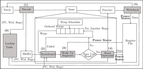
Figure 5 shows the modified pipeline of GPU Architecture that supports our proposed ideas, with the modified components shaded and labeled. The changes are described below and the corresponding overheads are quantified in Section 5.6.
- (1)
-
(2)
The scoreboard unit (Label (2)) is modified to track RAR (Read After Read) and WAR (Write after Read) dependencies in addition to RAW (Read After Write) and WAW (Write after Write) dependencies. This is done by adding instruction’s source registers in the scoreboard table. It is because an instruction can change the power state of a register to SLEEP or OFF after reading the registers. Hence, the subsequent instructions that read/write the same register need to wait until the power state is modified.
-
(3)
The registers in SLEEP or OFF state are woken up by sending a wake up signal to the register file (Label (3)). A warp is considered ready for issuing its current instruction only when all its operand registers are in ON state.
-
(4)
The read operands phase (Label (4)) is modified (a) to set the power state of source registers after they have been read and (b) to release the source registers of the instruction which were reserved by the scoreboard unit.
-
(5)
The write back stage (Label (5)) includes the logic to set the power state of the destination registers after the registers are written.
-
(6)
The run-time optimization is implemented by adding a lookup table (Label (6)) to keep track of the registers accessed by an instruction. For an instruction having program counter PC and warp id Wid, the lookup table is indexed by Wid. When an instruction is decoded, the decode unit inserts the instruction’s operand registers into the lookup table. When a warp (Wid) needs to set the power state of a register () of an instruction (PC) to SLEEP or OFF, it searches the lookup table for another instruction (a different PC) with the same Wid and accessing . If a match is found, then the power state of is kept ON, otherwise, it is changed. After an instruction completes its writeback stage, the corresponding entry is removed from the lookup table.
Each entry for a warp in the look up table stores instruction’s PC, and its register numbers. The number of entries required for each warp is determined by the pipeline depth, which can be large. However, in practice, the number of entries required per each warp is less, and experimentally we found that the average number of entries per warp is less than 2. If an SM allows maximum resident warps, stores entries per each warp, supports operand registers for each instruction, and allows maximum registers per each thread, then the size of look up table (in bits) is .
4. Evaluation Methodology
We implemented the proposed hardware changes and compiler optimizations in GPGPU-Sim V3.x (GPGPUSIM, 2014). The modified instruction format is implemented by extending the PTXParser provided by GPGPU-Sim. The GPGPU-Sim configuration used for the experiments is shown in Table 2. We used GPUWattch (Leng et al., 2013) to measure the power consumption of register file.
| Resource | Configuration |
|---|---|
| Architecture | NVIDIA Tesla K20x |
| Number of SMs | 14 |
| Shader Core Clock | 732 MHz |
| Technology Node | 22nm |
| Register File Size per SM | 256KB |
| Number of Register Banks | 32 |
| Max Number of TBs per SM | 16 |
| Max Number of Threads per SM | 2048 |
| Warp Scheduling | LRR |
| Number of Schedulers per SM | 4 |
Note that GPUWattch internally uses CACTI (Cacti, 1994) to measure the power dissipation that does not support leakage power saving mechanism. Therefore, we modified GPUWattch to use CACTI-P (Li et al., 2011) that provides power gating technique, which can minimize the leakage power by setting the SRAM cells into low power (SLEEP or OFF) state. It uses minimum data retention voltage so that SRAM cells can enter into SLEEP state without losing their data. We chose SRAMvccmin to be the default value (provided by CACTI-P depending on the technology node, 22nm for this case). To put SRAM cells in OFF state, we configured SRAMvccmin to 0 V. In GPUs, the registers are allocated to each warp in a private manner. To independently turn the power state of warp registers into OFF, SLEEP, and ON states, we set the granularity of the subarray size in CACTI-P (Li et al., 2011) to 1 warp register (a set of 32 registers). After running several experiments, we chose the threshold value () as 3, which achieves lowest energy for maximum number of kernels. We used the latency to wake up a register from SLEEP to ON state to be 1 cycle as reported in (Li et al., 2011), and the latency to wake up a register from OFF to ON state be twice (i.e., 2 cycles) (Li et al., 2013), except for Section 5.7 where we consider the effect of other values for the wake up latencies on performance and energy consumption. We report these latency and energy overheads in Section 5.6 and also include these overheads throughout our results.
We evaluated GReEneR on several applications from the benchmark suites CUDA-SDK (CUDA-SDK, 2014), GPGPU-SIM (Bakhoda et al., 2009), Parboil (Parboil, 2012), and Rodinia (Che et al., 2009). Table 3 shows the list of applications and kernel that is simulated for each application. We compiled all the applications using CUDA-4.0222GPGPU-Sim does not support above CUDA 4.0.. We measured the effectiveness of our approach using the following metrics: (1) Power, (2) Energy, (3) Simulation Cycles.
| Sr. No. | Benchmark | Application | Notation | Kernel | Sr. No. | Benchmark | Application | Notation | Kernel |
|---|---|---|---|---|---|---|---|---|---|
| 1 | RODINIA | backprop | BP | bpnn_adjust | 12 | GPGPU-SIM | MUM | MUM | mummergpuKernel |
| weights_cuda | |||||||||
| 2 | RODINIA | bfs | BFS1 | Kernel | 13 | GPGPU-SIM | NN | NN1 | executeFirstLayer |
| 3 | RODINIA | bfs | BFS2 | Kernel2 | 14 | GPGPU-SIM | NN | NN2 | executeSecondLayer |
| 4 | CUDA-SDK | Blackscholes | BS | BlackScholesGPU | 15 | GPGPU-SIM | NN | NN3 | executeThirdLayer |
| 5 | RODINIA | lavaMD | LMD | kernel_gpu_cuda | 16 | GPGPU-SIM | NN | NN4 | executeFourthLayer |
| 6 | GPGPU-SIM | LIB | LIB | Pathcalc_Portfolio_ | 17 | RODINIA | pathfinder | PF | dynproc_kernel |
| KernelGPU | |||||||||
| 7 | GPGPU-SIM | LPS | LPS | GPU_laplace3d | 18 | CUDA-SDK | scalarProd | SP | scalarProdGPU |
| 8 | CUDA-SDK | MonteCarlo | MC1 | inverseCNDKernel | 19 | PARBOIL | sgemm | SGEMM | mysgemmNT |
| 9 | CUDA-SDK | MonteCarlo | MC2 | MonteCarloOne | 20 | PARBOIL | spmv | SPMV | spmv_jds |
| BlockPerOption | |||||||||
| 10 | PARBOIL | mri-q | MR1 | ComputePhi | 21 | CUDA-SDK | vectorAdd | VA | VecAdd |
| Mag_GPU | |||||||||
| 11 | PARBOIL | mri-q | MR2 | ComputeQ_GPU |
5. Experimental Results
In the results, we compare GReEneR with Basline approach, which is the default approach that does not use any leakage power saving mechanisms. Also, we compare it with warped register file (Abdel-Majeed and Annavaram, 2013) technique (denoted as Sleep-Reg), which comes closest to our work. Sleep-Reg optimizes the baseline approach by (1) turning OFF the unallocated registers and (2) turning the allocated registers into SLEEP state immediately after the registers are accessed.
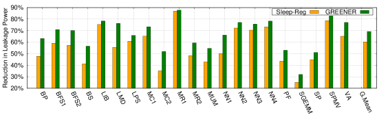
5.1. Comparing Register Leakage Power
Figure 6 shows the effectiveness of GReEneR and Sleep-Reg by measuring the reduction in leakage power with respect to Baseline. From the figure, we observe that GReEneR shows an average (Geometric Mean denoted as G.Mean) reduction of leakage power by 69.21% when compared to the Baseline. It shows the GReEneR is effective in turning the instruction registers into lower power state, such as SLEEP or OFF state depending on the behavior of the registers. The Baseline does not provide any mechanism to save the leakage power, as a result, the registers of a warp continue to consume leakage power throughout the warp execution. Figure 6 also shows that Sleep-Reg approach reduces the register leakage power by 60.23% when compared to Baseline, however, GReEneR is more power efficient than Sleep-Reg. It is because Sleep-Reg approach reduces the leakage power by turning the instruction registers into SLEEP state immediately after the instruction operands are accessed, without considering the access pattern of the registers. If a register needs an immediate access, then keeping the register into SLEEP instead of ON state requires additional latency cycles to wake up the register, and during these additional cycles, the registers consume power. Further, GReEneR saves more leakage power compared to Sleep-Reg by turning the registers into OFF state when there is no future use of the register, whereas Sleep-Reg turns the register into only SLEEP state irrespective of its further usage.
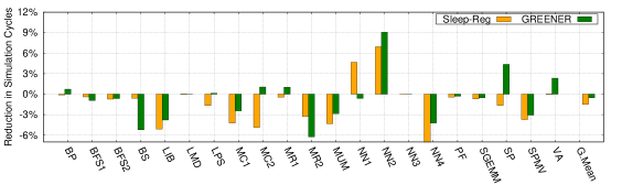
5.2. Performance Overhead Using Simulation Cycles
Figure 7 shows the performance overheads of GReEneR and Sleep-Reg approaches in terms of the number of simulation cycles with respect to Baseline. On an average, the applications show a negligible performance overhead of 0.53% with respect to Baseline. A slowdown is expected because GReEneR turns the registers into SLEEP or OFF states to enable power savings, and these registers are turned back to ON state (woken up) when they need to be accessed. This wake up process takes few additional latency cycles which leads to increase in the number of simulation cycles. Interestingly, some applications (BP, LPS, MC2, MR1, NN2, SP, and VA) show improvement in their performance. This occurs due to the change in the issuing order of the instructions. The warps that require their registers to be woken up can not be issued in its current cycle, instead other resident warps that are ready can be issued. This change in the issue order leads to change in the memory access patterns, which in turns changes L1 and L2 cache misses etc. In case of BP, LPS, MC2, and NN1 applications, we observe an improvement in the performance due to less number of pipeline stall cycles with GReEneR when compared to Baseline. MR1 shows less number of scoreboard stall cycles with GReEneR when compared to Baseline. Though SP and VA applications have same number L1 and L2 cache misses with GReEneR and Baseline approach, GReEneR shows less number of pipeline stall cycles when compared to Baseline.
Figure 7 also shows that Sleep-Reg has an average performance degradation of 1.48% when compared to the Baseline approach. This degradation is more when compared to GReEneR because Sleep-Reg turns all the instruction registers into SLEEP state after the instruction operands are accessed, irrespective of their usage pattern. If a register in SLEEP state is accessed in near future, it needs to be turned on, this incurs additional wake up latencies with Sleep-Reg. Whereas, our approach minimizes these additional wake up latency cycles by retaining such registers in the ON state. However, MR2 performs better with Sleep-Reg because it shows less number of scoreboard and idle cycles than that of GReEneR. Also, Sleep-Reg performs better with BS and NN1 since it has less number of stall cycles when compared to GReEneR.
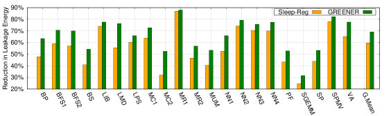
5.3. Comparing Register Leakage Energy
Figure 8 compares the total energy savings of GReEneR and Sleep-Reg w.r.t. Baseline. The results show that GReEneR achieves an average reduction of register leakage energy by 69.04% and 23.29% when compared to Baseline and Sleep-Reg respectively. From Figures 6 and 7, we see that GReEneR shows more leakage power saving, also has negligible performance overhead with respect to the Baseline, hence we achieve a significant reduction in leakage energy. Also, the applications that exhibit more power savings and improve their performance with GReEneR, further show more leakage energy savings. Similarly, the applications that show leakage power savings but has more performance overhead will reduce their leakage energy savings accordingly when compared to Baseline and Sleep-Reg approaches.
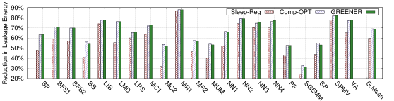
5.4. Effectiveness of Optimizations
We show the effectiveness of the proposed optimizations in Figure 9. From the figure, we analyze that the compiler optimization (discussed in Section 3.1, and denoted as Comp-OPT) saves more energy (average 69.09%) when compared to Sleep-Reg (59.65%). This shows that turning the registers into low power states (SLEEP or OFF state) with the knowledge of register access pattern is more effective than turning the registers into SLEEP state after accessing them.
The run-time optimization (discussed in Section 3.3) is evaluated by combining it with Comp-OPT, and we denote them as GReEneR in the figure. From the results, we observe that, for most of the applications, GReEneR show minor improvements when compared to Comp-OPT respectively. This is because the run-time optimization helps only in correcting power state of a register by turning to ON state when it detects the future access to the register at run-time. However, if the register is not found to be accessed in the near future at run-time, it does not modify and retains the power state as directed by the Comp-OPT. For some applications (e.g. NN3), GReEneR is less efficient when compared to Comp-OPT. It occurs when a register that is determined to be accessed in the near future does not get accessed due to reasons such as scheduling order, scoreboard stalls, or the unavailability of the corresponding execution unit. In those cases, keeping the register into low power states (SLEEP or OFF) can save more energy instead of keeping it in ON state. Note that the effectiveness of run-time optimization depends on the application behavior at the branch divergence points.
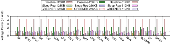
5.5. Leakage Power with Different Register File Sizes
Figure 10 shows the effect of register file size on leakage power for Baseline, Sleep-Reg, and GReEneR approaches. The register file sizes used are 128KB, 256KB, and 512KB. In the figure, Baseline-128KB denotes the Baseline approach that is evaluated with 128KB register file size. The other approaches are tagged in a similar way.
From the figure, we can see that for all the three approaches, leakage power increases with the increase in the register file size. This is because each memory cell in the register file consumes some amount of leakage power, and with the increase in the number of registers, leakage power increases. However, for Sleep-Reg and GReEneR, this increase in the leakage power is less when compared to Baseline since the register files in Baseline consume leakage power irrespective of the register access. Whereas, registers can be put to lower power states with Sleep-Reg and GReEneR. The results also indicate that GReEneR is effective when compared to Sleep-Reg and Baseline even with the increase in register file size.
Interestingly, GReEneR with 512KB register file configuration consumes less amount of leakage power than that of Baseline with 256KB configuration. Also, the leakage power of GReEneR for 512KB configuration is comparable to that of Baseline-128KB. This shows that GReEneR with twice the register file size compared to Baseline, not only shows less amount of leakage power consumption, but also can improve the amount of thread level parallelism.
5.6. Analyzing Hardware Overheads
To support leakage power saving, CACTI-P (Li et al., 2011) introduces additional sleep transistors into the SRAM structures. These transistors enable us to put the registers into low power states (SLEEP or OFF) after accessing the operands (discussed in Section 3.4), also they enable us to wake up the registers from lower power states before accessing the operands. For the configuration used in our experiments, Table 4 shows the additional area, latency, and energy associated with the additional sleep transistors circuitry. Note that in our experiments, we conservatively consider the latency overhead to change the power state of a register from OFF to ON state to be 2 cycles.
Recall that GReEneR encodes the power state of a register with its instruction, and we require 6 bits to encode the power states of the instruction registers. Currently, NVIDIA does not disclose the machine code format of the instructions. However, we can adopt either of the following two solutions as described in (Sami et al., 2002). (1) If the instruction format has 6 unused bits, we can exploit these bits to encode the power states. In this case, the instruction length would not increase, and there is no additional power overhead. (2) If there are no unused bits in the instruction format, we can extend the instruction length by 6 bits to encode the power states. However, this incurs additional storage in the GPU pipeline, such as instruction buffers overhead. We measure the additional overhead using GPUWattch framework by increasing the instruction length by 8 bits (2-bit padding for byte alignment). We observe that adding 8 bits to the instruction has 0.0001% area overhead and 0.005% leakage power overhead in each SM.
| Parameter | Overhead |
|---|---|
| Area | 0.00875 |
| Wake up Latency (SLEEP to ON) | 0.0197 ( 1 clock cycle) |
| Wake up Latency (OFF to ON state) | 0.0551 ( 1 clock cycle) |
| Energy (SLEEP to ON and vice versa) | 0.0633 |
| Energy (OFF to ON and vice versa) | 0.198 |
As discussed in Section 3.4, we are required to modify scoreboard unit in the scheduler unit to keep track of the read after read dependencies. Currently, GPUWattch does not support a power model for scoreboard unit. However, depending on the following design choices we may require additional overheads. (1) If the power model for scoreboard uses a bit mask to keep track of the registers accessed by a warp, then we do not require any additional storage overhead. We can use the existing bit mask to set the registers that will be read by a warp. (2) Instead, if the scoreboard explicitly maintains the register numbers accessed by each warp, then we need to store up to 4 source register numbers of an instruction. If each SM allows resident warps, and has registers per each thread, then the additional storage overhead for this scheme is . For the configuration used in our experiments (i.e., W=64, R=64), the storage overhead is 192 bytes, which is 0.1% of register file size. Similarly, to support the run-time optimization, we require a look up table. For our experiments, the additional storage required for lookup table is 1280 bytes ( 1% of the register file size).
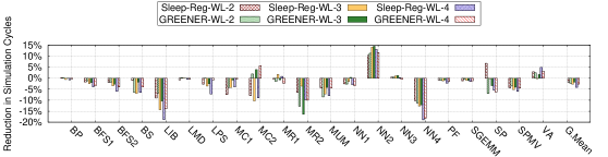
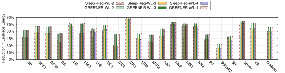
5.7. Effect of Wake up Latency
Figure 11 compares performance overhead of GReEneR and Sleep-Reg with the Baseline for different values of wake up latencies. In the figure, GReEneR-WL-X (X {2,3,4}) denotes the GReEneR approach, which considers the wake up latency to change a register state from SLEEP to ON to be X cycles. Whereas, when a register state needs to be changed from OFF to ON, it considers the latency to be 2X cycles. We use the similar notation for Sleep-Reg as well.
For most of the applications, GReEneR and Sleep-Reg show performance degradation with the increase in the wake up latency. The increase in the overhead is expected because applications spend additional simulation cycles for changing register’s state from OFF or SLEEP state to ON state. Hence, with the increase in the wake up latency, these additional simulation cycles will increase. Interestingly, some applications (MC1 and MC2) show performance improvement with the increase in the wake up latency. This is because, as discussed in Section 5.2, with the addition of wake up latency, the warps in the SM can get issued in different order, which can change the number of L1-cache misses, L2-cache misses, and stall cycles etc. For MC1 and MC2, we find that the number pipeline stall cycles decrease with increase in the wake up latencies. Similarly, for NN2 we observe more number of L1 misses with GReEneR when used with wake latency 2 cycles than that of 3 cycles, hence GReEneR performs better with wake up latency 3 cycles. Also, for NN2, GReEneR performs better than Baseline for all wake up latencies due to a decrease in the L1 misses when compared to Baseline. In case of SP, GReEneR-WL-2 has more stall cycles when compared to GReEneR-WL-3. Further, for most of the applications GReEneR performs better than Sleep-Reg with various wake up latencies.
We also compare the energy savings by varying the wake up latencies as shown in Figure 12. The results indicate that even with varying the wake up latency, the applications show significant reduction in the leakage energy when compared to Baseline. Also, the applications show more energy savings with GReEneR when compared to Sleep-Reg for all wake up latencies.
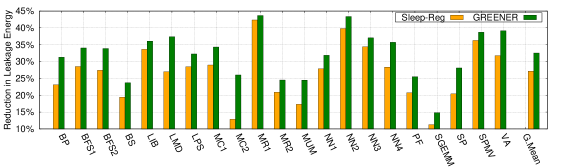
5.8. Leakage Energy Savings with Routing
So far we discussed the energy efficiency of registers in a register file, however, GPUs also consume energy for routing of data and address through the register file. While modeling the register file, McPAT uses H-Tree distribution network to route data and address (Li et al., 2013). The H-Tree network spends a constant amount of leakage power, and various organizations can be exploited to reduce this power and to meet routing requirement (Cacti, 1994). Our work focuses only on reducing the leakage power of memory cells of the register file by analyzing the register access patterns, and reducing the routing power is not in this scope. However, we show the effectiveness of GReEneR by including the constant routing energy as shown in Figure 13. From the results, we observe that GReEneR reduces the leakage energy on an average by 32.54% when compared to Baseline, which is more than that of Sleep-Reg (27.15%). However, the energy savings when including the routing energy are reduced when compared to that of results in Figure 8 because GReEneR does not provide any mechanism to optimize the routing power, hence the routing power remains unaffected.
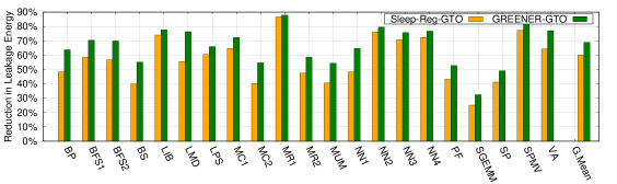
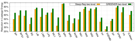
5.9. Leakage Energy Savings with Different Schedulers
Figure 14 and 15 show the effectiveness of GReEneR when it is evaluated with GTO and two-level scheduling policies respectively. The figures compare GReEneR and Sleep-Reg with Baseline by measuring the reduction in leakage energy for the corresponding scheduling policies. The results show that GReEneR-GTO and GReEneR-two-level achieve an average reduction leakage energy by 68.95% and 69.64% with respect to Baseline-GTO and Baseline-two-level respectively. With different scheduling policies, the warps in the SM have different interleaving patterns, which affect the distance between the two consecutive accesses to a register. Even with the change in these access patterns, GReEneR shows reduction in leakage energy when compared to Baseline and Sleep-Reg. We also find that Baseline-GTO performs better than Baseline-two-level in terms of simulation cycles, hence Baseline-GTO relatively consumes less leakage energy when compared to Baseline-two-level. However, the average energy savings of GReEneR are not affected significantly even with change in the scheduler.
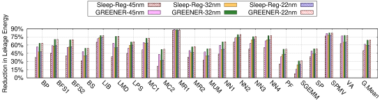
5.10. Leakage Energy with Various Technologies
Figure 16 shows the effectiveness of GReEneR for various technology parameters (45nm, 32nm, and 22nm). The results show a significant reduction in leakage energy with GReEneR for all the applications even for various technology nodes. Further, it reduces the energy when compared to Sleep-Reg. With transition of technology from 45nm to 32nm, we observe an increase in the leakage energy for the Baseline approach, but GReEneR shows an increase in the leakage energy savings even with the transition. To model 22nm technology node, McPAT uses double gated technology to reduce the amount of leakage power, even with the advances in technology, GReEneR shows a reduction in leakage power when compared to Baseline. To summarize, architectural techniques help in reducing the leakage power of a register file, in addition, the knowledge of register access patterns and compiler optimizations further help in reducing the leakage power and energy.
6. Related Work
Leakage and dynamic power are the two major sources of power dissipation in CMOS technology. Reducing the leakage and dynamic power has been well studied in the context of CPUs when compared to GPUs. Though GReEneR is only for saving leakage power consumption of GPU register files, we describe briefly the techniques to save leakage and dynamic power in the context of both CPUs as well as GPUs. A comprehensive list of architectural techniques to reduce leakage and dynamic power of CPUs are described in (Kaxiras and Martonosi, 2008). Mittal et al. (Mittal, 2017) discuss the state of the art approaches for reducing the power consumption of CPU register file. A survey of methods to reduce GPU power is presented in (Mittal and Vetter, 2014).
6.1. CPU Leakage Power Saving Techniques
Powell et al. (Powell et al., 2000) proposed a state destroying technique, Gated-, to minimize the leakage power of SRAM cells by gating supply voltage. Several methods (Yang et al., 2001; Kaxiras et al., 2001; Zhang and Asanović, 2002) leverage Gated- technique to reduce the leakage power of cache memory by turning off the inactive cache lines. However, these techniques cannot preserve the state of the cache lines. To maintain the state, Flautner et al. (Flautner et al., 2002) proposed an architectural technique that reduces the leakage power by putting the cache lines into a drowsy state. Other approaches (Hu et al., 2003; Petit et al., 2005) exploit this by using cache access patterns to put cache lines in the drowsy state. As expected, the leakage power savings in this (drowsy) approach are less when compared to Gated- approach.
6.2. GPU Leakage Power Saving Techniques
Warped register file (Abdel-Majeed and Annavaram, 2013) reduces leakage power of register files by putting the registers into the drowsy state immediately after accessing them. However, it does not take into account the register access pattern while turning the registers into low power states, hence it can have high overhead whenever there are frequent wake up signals to the drowsy registers. In contrast, GReEneR considers register access information and proposes compile-time and run-time optimizations to make the register file energy efficient. Their approach is closest to GReEneR and has been quantitatively compared in Section 5.
Register file virtualization (Jeon et al., 2015) reduces the register leakage power by reallocating unused registers to another warp. This uses additional meta instructions to turn off the unused registers. However, the meta instructions are inserted at every 18 instructions, which can cause a delay in turning off the registers. GReEneR encodes the power saving states of the registers in the same instruction, and hence the registers can be switched to low power state at the earliest. Their approach optimizes power for unused registers only, while GReEneR can put even a used register into low power state if the next use is far away in the execution.
Pilot register file (Abdel-Majeed et al., 2017) partitions the register file into fast and slow register files, and it allocates the registers into these parts depending on the frequency of the register usage. It uses compiler and profiling information to allocate the register into one of these parts. The partition of the registers is done statically. Therefore, if a register is accessed more frequently for some duration, and less frequently for other duration, then allocating the register to either of the partitions can make it less energy efficient. GReEneR changes power state during the execution, so it does not suffer from this drawback.
Warped Gates (Abdel-Majeed et al., 2013) exploits the idle execution units to reduce the leakage power with a gating aware scheduling policy. This approach is complementary to GReEneR and it should be possible to combine the two techniques to further reduce leakage power.
6.3. Dynamic Power Saving Techniques for CPU and GPU
In CPUs, dynamic voltage frequency scaling (DVFS) has been widely adopted at the system level (Weiser et al., 1994), compiler level (Xie et al., 2003; Hsu and Kremer, 2003), and hardware level (Semeraro et al., 2002) to reduce dynamic power consumption. In case of GPUs, equalizer (Sethia and Mahlke, 2014) dynamically adjusts the core and memory frequencies depending on the application behavior and the user requirement (i.e., power or performance). Lee et al. (Lee et al., 2011) propose mechanisms to dynamically adjust the voltage and frequency values to improve the throughput of applications under the power constraints. GPUWattch (Leng et al., 2013) uses DVFS algorithm to reduce the dynamic power by adjusting the processor frequency depending on the number of stall cycles. Warped compression (Lee et al., 2015) exploits the register value similarity to reduce effective register file size to minimize the dynamic as well as leakage power. Gebhart et al. (Gebhart et al., 2012) propose two complementary techniques to reduce GPU energy. The hierarchical register file proposed by them reduces register file energy by replacing the single register file with a multilevel hierarchical register file. Further, they design a multi level scheduler that partitions warps to active and pending warps and propose mechanisms to schedule these warps to achieve energy efficiency. These techniques mainly focus on reducing the dynamic power of GPUs and are orthogonal to our approach.
6.4. Miscellaneous
Seth et al. (Seth et al., 2001) present algorithmic strategies for insertion of processor idle instructions at various points in the program such that the overall energy is reduced. Sami et al. (Sami et al., 2002) employ liveness analysis to reduce the register file power in VLIW embedded architectures. Their approach exploits operand forwarding paths to minimize the number of register accesses of short lived registers. Hence, their mechanism is beneficial to the applications that have large number of short living registers.
7. Conclusions and Future Work
This paper focuses on reducing the leakage power of the register file in GPUs. We discuss various opportunities to save leakage power of the registers by analyzing the access patterns of the registers. We propose a new assembly instruction format that supports the power states of instruction’s registers. Further, we provide a compiler analysis that determines the power state of each register at each program point, also transforms an input assembly to power optimized assembly code. To improve the effectiveness further, we introduce a run-time optimization that dynamically corrects the power states determined by the static analysis.
We implemented the proposed ideas in GPGPU-Sim simulator and evaluated them on several kernels from CUDASDK, GPGPU-SIM, Parboil, and Rodinia benchmark suites. We achieved an average reduction of leakage energy by 69.04% and maximum reduction of 87.95% with a negligible performance overhead when compared to baseline approach.
The register leakage power constitutes a part of the total leakage power. Similarly, other resources in the GPU such as shared memory, cache, and DRAM, dissipate leakage power during a kernel execution. In future, we plan to work on reducing the power consumption of the other GPU resources by analyzing the application behavior and the resource access patterns.
References
- (1)
- Abdel-Majeed and Annavaram (2013) Mohammad Abdel-Majeed and Murali Annavaram. 2013. Warped Register File: A Power Efficient Register File for GPGPUs. In Proceedings of the 2013 IEEE 19th International Symposium on High Performance Computer Architecture (HPCA) (HPCA ’13). IEEE Computer Society, 412–423.
- Abdel-Majeed et al. (2017) Mohammad Abdel-Majeed, Alireza Shafaei, Hyeran Jeon, Massoud Pedram, and Murali Annavaram. 2017. Pilot Register File: Energy Efficient Partitioned Register File for GPUs. In 2017 IEEE International Symposium on High Performance Computer Architecture, HPCA 2017, Austin, TX, USA, February 4-8, 2017. 589–600.
- Abdel-Majeed et al. (2013) Mohammad Abdel-Majeed, Daniel Wong, and Murali Annavaram. 2013. Warped Gates: Gating Aware Scheduling and Power Gating for GPGPUs. In Proceedings of the 46th Annual IEEE/ACM International Symposium on Microarchitecture (MICRO-46). ACM, 111–122.
- Bakhoda et al. (2009) A. Bakhoda, G. L. Yuan, W. W. L. Fung, H. Wong, and T. M. Aamodt. 2009. Analyzing CUDA workloads using a detailed GPU simulator. In 2009 IEEE International Symposium on Performance Analysis of Systems and Software. 163–174.
- Cacti (1994) Cacti 1994. An integrated cache and memory access time, cycle time, area, leakage, and dynamic power model. http://www.hpl.hp.com/research/cacti. (1994).
- Che et al. (2009) Shuai Che, Michael Boyer, Jiayuan Meng, David Tarjan, Jeremy W. Sheaffer, Sang-Ha Lee, and Kevin Skadron. 2009. Rodinia: A Benchmark Suite for Heterogeneous Computing. In Proceedings of the 2009 IEEE International Symposium on Workload Characterization (IISWC) (IISWC ’09). IEEE Computer Society, 44–54.
- CUDA (2012) CUDA 2012. CUDA C Programming Guide. http://docs.nvidia.com/cuda/pdf/CUDA_C_Programming_Guide.pdf. (2012).
- CUDA-SDK (2014) CUDA-SDK 2014. CUDA-SDK. http://docs.nvidia.com/cuda/cuda-samples. (2014).
- Flautner et al. (2002) Krisztián Flautner, Nam Sung Kim, Steve Martin, David Blaauw, and Trevor Mudge. 2002. Drowsy Caches: Simple Techniques for Reducing Leakage Power. SIGARCH Comput. Archit. News 30, 2 (May 2002), 148–157.
- Gebhart et al. (2012) Mark Gebhart, Daniel R. Johnson, David Tarjan, Stephen W. Keckler, William J. Dally, Erik Lindholm, and Kevin Skadron. 2012. A Hierarchical Thread Scheduler and Register File for Energy-Efficient Throughput Processors. ACM Trans. Comput. Syst. 30, 2, Article 8 (April 2012), 38 pages.
- GPGPUSIM (2014) GPGPUSIM 2014. GPGPU-Sim Simulator. http://www.gpgpu-sim.org. (2014).
- Hsu and Kremer (2003) Chung-Hsing Hsu and Ulrich Kremer. 2003. The Design, Implementation, and Evaluation of a Compiler Algorithm for CPU Energy Reduction. In Proceedings of the ACM SIGPLAN 2003 Conference on Programming Language Design and Implementation (PLDI ’03). ACM, 38–48.
- Hu et al. (2003) J. S. Hu, A. Nadgir, N. Vijaykrishnan, M. J. Irwin, and M. Kandemir. 2003. Exploiting Program Hotspots and Code Sequentiality for Instruction Cache Leakage Management. In Proceedings of the 2003 International Symposium on Low Power Electronics and Design (ISLPED ’03). ACM, 402–407.
- Jeon et al. (2015) Hyeran Jeon, Gokul Subramanian Ravi, Nam Sung Kim, and Murali Annavaram. 2015. GPU Register File Virtualization. In Proceedings of the 48th International Symposium on Microarchitecture (MICRO-48). ACM, 420–432.
- Kaxiras et al. (2001) Stefanos Kaxiras, Zhigang Hu, and Margaret Martonosi. 2001. Cache Decay: Exploiting Generational Behavior to Reduce Cache Leakage Power. In Proceedings of the 28th Annual International Symposium on Computer Architecture (ISCA). ACM, 240–251.
- Kaxiras and Martonosi (2008) Stefanos Kaxiras and Margaret Martonosi. 2008. Computer Architecture Techniques for Power-Efficiency (1st ed.). Morgan and Claypool publishers.
- Kepler (2012) Kepler 2012. NVIDIA Next Generation CUDA Compute Architecture. https://www.nvidia.com/content/PDF/kepler/NVIDIA-Kepler-GK110-Architecture-Whitepaper.pdf. (2012).
- Khedker et al. (2009) Uday Khedker, Amitabha Sanyal, and Bageshri Karkare. 2009. Data Flow Analysis: Theory and Practice (1st ed.). CRC Press, Inc., Boca Raton, FL, USA.
- Kim et al. (2003) Nam Sung Kim, Todd Austin, David Blaauw, Trevor Mudge, Krisztián Flautner, Jie S. Hu, Mary Jane Irwin, Mahmut Kandemir, and Vijaykrishnan Narayanan. 2003. Leakage Current: Moore’s Law Meets Static Power. Computer 36, 12 (Dec. 2003), 68–75.
- Lee et al. (2011) Jungseob Lee, Vijay Sathisha, Michael Schulte, Katherine Compton, and Nam Sung Kim. 2011. Improving Throughput of Power-Constrained GPUs Using Dynamic Voltage/Frequency and Core Scaling. In Proceedings of the 2011 International Conference on Parallel Architectures and Compilation Techniques (PACT ’11). IEEE Computer Society, 111–120.
- Lee et al. (2015) Sangpil Lee, Keunsoo Kim, Gunjae Koo, Hyeran Jeon, Won Woo Ro, and Murali Annavaram. 2015. Warped-compression: Enabling Power Efficient GPUs Through Register Compression. In Proceedings of the 42Nd Annual International Symposium on Computer Architecture (ISCA ’15). ACM, 502–514.
- Leng et al. (2013) Jingwen Leng, Tayler Hetherington, Ahmed ElTantawy, Syed Gilani, Nam Sung Kim, Tor M. Aamodt, and Vijay Janapa Reddi. 2013. GPUWattch: Enabling Energy Optimizations in GPGPUs. In Proceedings of the 40th Annual International Symposium on Computer Architecture (ISCA ’13). ACM, 487–498.
- Li et al. (2013) Sheng Li, Jung Ho Ahn, Richard D. Strong, Jay B. Brockman, Dean M. Tullsen, and Norman P. Jouppi. 2013. The McPAT Framework for Multicore and Manycore Architectures: Simultaneously Modeling Power, Area, and Timing. ACM Trans. Archit. Code im. 10, 1, Article 5 (April 2013), 29 pages.
- Li et al. (2011) Sheng Li, Ke Chen, Jung Ho Ahn, Jay B. Brockman, and Norman P. Jouppi. 2011. CACTI-P: Architecture-level Modeling for SRAM-based Structures with Advanced Leakage Reduction Techniques. In Proceedings of the International Conference on Computer-Aided Design (ICCAD ’11). IEEE Press, 694–701.
- Mittal (2017) Sparsh Mittal. 2017. A survey of techniques for designing and managing CPU register file. Concurrency and Computation: Practice and Experience 29, 4 (2017).
- Mittal and Vetter (2014) Sparsh Mittal and Jeffrey S. Vetter. 2014. A Survey of Methods for Analyzing and Improving GPU Energy Efficiency. ACM Comput. Surv. 47, 2, Article 19 (Aug. 2014), 23 pages.
- Parboil (2012) Parboil 2012. Parboil Benchmarks. http://impact.crhc.illinois.edu/Parboil/parboil.aspx. (2012).
- Petit et al. (2005) Salvador Petit, Julio Sahuquillo, Jose M. Such, and David Kaeli. 2005. Exploiting Temporal Locality in Drowsy Cache Policies. In Proceedings of the 2Nd Conference on Computing Frontiers (CF ’05). ACM, 371–377.
- Powell et al. (2000) Michael Powell, Se-Hyun Yang, Babak Falsafi, Kaushik Roy, and T. N. Vijaykumar. 2000. Gated-Vdd: A Circuit Technique to Reduce Leakage in Deep-submicron Cache Memories. In Proceedings of the 2000 International Symposium on Low Power Electronics and Design (ISLPED ’00). ACM, 90–95.
- Sami et al. (2002) M. Sami, D. Sciuto, C. Silvano, V. Zaccaria, and R. Zafalon. 2002. Low-power data forwarding for VLIW embedded architectures. IEEE Transactions on Very Large Scale Integration (VLSI) Systems 10, 5 (Oct 2002), 614–622.
- Semeraro et al. (2002) Greg Semeraro, David H. Albonesi, Steven G. Dropsho, Grigorios Magklis, Sandhya Dwarkadas, and Michael L. Scott. 2002. Dynamic Frequency and Voltage Control for a Multiple Clock Domain Microarchitecture. In Proceedings of the 35th Annual ACM/IEEE International Symposium on Microarchitecture (MICRO 35). IEEE Computer Society Press, 356–367.
- Seth et al. (2001) Anil Seth, Ravindra B. Keskar, and R. Venugopal. 2001. Algorithms for Energy imization Using Processor Instructions. In Proceedings of the 2001 International Conference on Compilers, Architecture, and Synthesis for Embedded Systems (CASES ’01). ACM, 195–202.
- Sethia and Mahlke (2014) Ankit Sethia and Scott Mahlke. 2014. Equalizer: Dynamic Tuning of GPU Resources for Efficient Execution. In Proceedings of the 47th Annual IEEE/ACM International Symposium on Microarchitecture (MICRO-47). IEEE Computer Society, 647–658.
- Weiser et al. (1994) Mark Weiser, Brent Welch, Alan Demers, and Scott Shenker. 1994. Scheduling for Reduced CPU Energy. In Proceedings of the 1st USENIX Conference on Operating Systems Design and Implementation (OSDI ’94). USENIX Association, Article 2.
- Xie et al. (2003) Fen Xie, Margaret Martonosi, and Sharad Malik. 2003. Compile-time Dynamic Voltage Scaling Settings: Opportunities and Limits. In Proceedings of the ACM SIGPLAN 2003 Conference on Programming Language Design and Implementation (PLDI ’03). ACM, 49–62.
- Yang et al. (2001) Se-Hyun Yang, Babak Falsafi, Michael D. Powell, Kaushik Roy, and T. N. Vijaykumar. 2001. An Integrated Circuit/Architecture Approach to Reducing Leakage in Deep-Submicron High-Performance I-Caches. In Proceedings of the 7th International Symposium on High-Performance Computer Architecture (HPCA). IEEE Computer Society, 147–157.
- Zhang and Asanović (2002) Michael Zhang and Krste Asanović. 2002. Fine-grain CAM-tag Cache Resizing Using Miss Tags. In Proceedings of the 2002 International Symposium on Low Power Electronics and Design (ISLPED). ACM, 130–135.