Compensating fictitious magnetic field gradients in optical microtraps by using elliptically polarized dipole light
Abstract
Tightly focused optical dipole traps induce vector light shifts (“fictitious magnetic fields”) which complicate their use for single-atom trapping and manipulation. The problem can be mitigated by adding a larger, real magnetic field, but this solution is not always applicable; in particular, it precludes fast switching to a field-free configuration. Here we show that this issue can be addressed elegantly by deliberately adding a small elliptical polarization component to the dipole beam. In our experiments with single 87Rb atoms in a chopped trap, we observe improvements up to a factor 11 of the trap lifetime compared to the standard, seemingly ideal linear polarization. This effect results from a modification of heating processes via spin-state diffusion in state-dependent trapping potentials. We develop Monte-Carlo simulations of the evolution of the atom’s internal and motional states and find that they agree quantitatively with the experimental data. The method is general and can be applied in all experiments where the longitudinal polarization component is non-negligible.
pacs:
37.10.Gh, 37.10.De, 42.25.JaI Introduction
When a linearly polarized electromagnetic beam is focussed so tightly that the paraxial approximation breaks down, its polarization near the focus is no longer purely transverse, but acquires a longitudinal component that increases with the confinement of the field and leads to polarization gradients in the strongly confined region. The effect has been known for a long time Richards and Wolf (1959), but currently gains importance in the context of light-matter interfaces with ultracold atoms. While similar effects play an enabling role in the new field of chiral quantum optics Lodahl et al. (2017), they complicate the use of strongly focussed, far-detuned laser beams for trapping and manipulating single atoms. Such single-atom tweezers Schlosser et al. (2001) are a powerful tool with many applications. They have been used, for example, to prepare a single trapped atom by collisional blockade Schlosser et al. (2001), to entangle single atoms by Rydberg blockade Urban et al. (2009); Gaëtan et al. (2009), to laser cool a single atom to its vibrational ground state Kaufman et al. (2012); Thompson et al. (2013a), and to couple an atom to a near-field optical structure Thompson et al. (2013b). When realized with a pigtailed optical fiber, a single-atom tweezer also enables an attractively simple source of narrowband single photons Garcia et al. (2013).
For standard dipole traps, the polarization is commonly chosen to be linear to ensure an equal light shift for all magnetic sublevels of the ground state Grimm et al. (2000). In single-atom tweezer experiments, where tight focussing is mandatory, the atom experiences an elliptical polarization with spatial variations on the wavelength scale even for a linearly polarized input field. The result is a vector light shift, which depends on the magnetic quantum number and can be described by a an effective, “fictitious” magnetic field Cohen-Tannoudji and Dupont-Roc (1972). One approach to mitigate this effect is to add a stronger, real magnetic field in a direction orthogonal to the fictitious field in order to reduce the field gradient Kaufman et al. (2012); Thompson et al. (2013a). It is however not always possible to add strong real magnetic fields, whose switching dynamics are usually slow.
In this article, we experimentally demonstrate that a properly chosen non-linear input polarization can be used instead of a real magnetic field to mitigate the damaging effects of vector light shift gradients. Our single-atom tweezer is chopped at rather high frequencies up to 4 MHz. In this way, spectroscopy, optical cooling and single-photon generation can be performed on an unperturbed atom during the field-free periods, while still providing a strong effective trapping potential Chu et al. (1986); Garcia et al. (2013); Hutzler et al. (2017). As we show, a slightly elliptical polarization for the input field of the chopped tweezer can improve the lifetime of the trapped atom by more than an order of magnitude. This is against the common belief that linear polarization is the best choice for an optical dipole trap, which actually holds only as long as the longitudinal component of the electromagnetic field can be neglected. We analyze how the experimental lifetime of the trapped atom depends on the trap chopping frequency and on the dipole light polarization. We then develop a model based on trap modifications due to quantum jumps between different Zeeman sub-states of the atom and perform Monte-Carlo simulations in very good agreement with the experimental data.
II Measurement of single atom lifetime for different polarizations
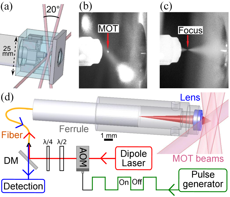
In our experimental setup (see Fig. 1) described in detail in Ref. Garcia et al. (2013), we have developed a miniature and robust fiber-pigtailed optical tweezer, where the same fiber is used to trap a single 87Rb atom and to read-out its fluorescence. We have also demonstrated that, once loaded, the pigtailed tweezer can be used as a single-photon source at 780 nm. To load the tweezer, we produce a laser-cooled atoms cloud in a magneto-optical trap (MOT) at the focus of a far off-resonance optical dipole trap with a wavelength close to 810 nm and a measured waist of m. To eliminate trap-induced light shifts, which reduce the efficiency of the MOT cooling, constitute a source of spectral broadening, and to avoid the generation of 780 nm photons by anti-Stokes Raman scattering of the trapping light inside the fiber, we chop the dipole light with an acousto-optical modulator (see Fig. 1.d) . If the chopping frequency is much larger than twice the largest trap oscillation frequency, the atom is expected to stay trapped in this attractive time-averaged potential. When the dipole light is on, the trap depth is mK, and the calculated transverse and longitudinal trap frequencies are kHz and kHz.
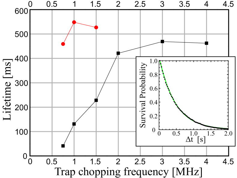
We have investigated the effect of the chopping frequency on the lifetime of the atom inside the trap (see Fig. 2) in the presence of the MOT beams used to load the dipole trap. The lifetime is obtained by an exponential fit of the survival probability of the atom versus the duration of the trapping. To be mainly limited by background gas collisions, we work in the weak loading regime, where loss due to a second atom entering the trap is negligible. For linearly polarized dipole light, the lifetime was limited by background gas collisions at a value of about ms for chopping frequencies above MHz. Below MHz, the lifetime decreases with the chopping frequencies and no single-atom trapping signal could be detected below 500 kHz. So, with this polarization, the chopping frequency needs to be much larger, by about one order of magnitude, than the largest calculated trap frequency. For chopping frequencies between kHz and MHz, we observe a strong improvement of the lifetime by adding a small circular component to the polarization of the dipole light. The lifetime is found optimal for an elliptical polarization characterized by the angle deg, where and are the semi-major and semi-minor axes of the electric-field ellipse, respectively. At a chopping frequency of kHz, the lifetime is improved by a factor .
These results cannot be explained by the chopping of the dipole light, which is expected to be negligible when the trap chopping frequency becomes higher than the largest parametric heating frequency () of the trap Savard et al. (1997). Moreover, this effect applies to all polarization configurations and so cannot explain the improved lifetime observed for slightly elliptical polarization. So, we can deduce from these results that additional heating mechanisms reduce the lifetime for a linearly dipole light and that this effect can be compensated by using an elliptical polarization.
III Effect of the polarization on the optical traps for the different Zeeman sub-levels
The modification of the lifetime induced by polarization finds its origin in the dipole potential of the ground state which depends on the Zeeman sub-level the atom occupies. For a dipole-light frequency close to the D1 and D2 transition frequencies of an alkali atom, this potential is given by Kuppens et al. (2000); Thompson et al. (2013a):
| (1) |
| (2) |
the scalar dipole potential. In these equations, is the natural linewidth of the excited P levels, are the detunings between the laser and the D1 and D2 transition frequencies ( respectively), the light intensity and the saturation intensity. We note the atom angular momentum operator (norm here) and . is a vector characterizing the ellipticity and direction of the polarization represented by a unit vector . For a polarization , we have : for linear polarization , and for a circular polarization . When is non-zero, the different sub-levels experience different light-shifts that are analogous to energy shifts induced by a fictitious magnetic field given by:
| (3) |
where is the Bohr magneton and is the Landé g-factor, which is equal to in the usual limits where the electron spin, electron orbital and nuclear Landé g-factors are approximated to , and , respectively.
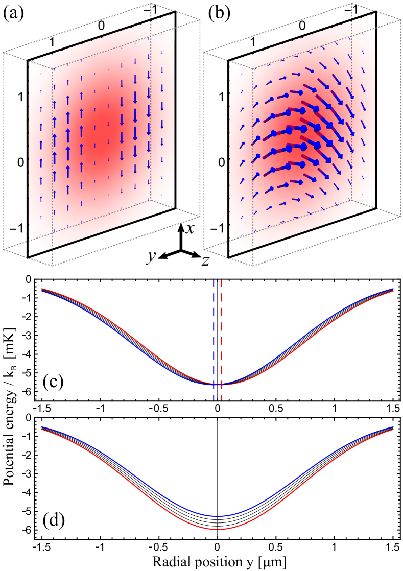
In our optical tweezer, a Gaussian beam is strongly focussed down to a waist m. For such a diverging beam, a purely transverse incident light (which is linearly-polarized along the -axis) generates at the focus plane strong variations of the local polarization due to interferences of the different focused light rays. The local characteristic vector is calculated via vector Debye integral Richards and Wolf (1959) and we plot the product , which is opposite of the fictitious magnetic field in our case, on Fig. 3.a. The effect is well approximated by a gradient of the vector. Figure 3.c presents the different potentials of the five sub-levels along the -axis in our trap by choosing the quantization axis of angular momentum as the unit vector of -axis. At first order, the traps are displaced with state-dependent trap centers:
| (4) |
We can see on Fig. 3.a that an atom crossing the -axis while maintaining its spin will see a flip of the orientation of the fictitious magnetic field. This situation is analogous to the evolution of atom spins crossing the center of a linear magnetic trap. In our linearly polarized dipole trap, the scalar potential provides an additional confinement which leads only to a displacement of the trap centers instead than spin flip losses.
If a large circular component is present in the polarization of the dipole light before the focus, it will induce a strong uniform -component of the vector, which will dominate over the linear polarization gradients, making them negligible. The dipole potential is then given by :
| (5) |
where the quantization axis of the angular momentum is chosen in the direction of the local vector. The traps of the different sub-levels have the same center, but differ in trap depth and oscillation frequencies, as shown by Fig. 3.d. This effect increases with the weight of the circular component of the polarization. As can be seen in Fig. 3.b, an atom crossing the -axis will experience a continuous evolution of the orientation of the fictitious magnetic field whose variation decreases when the circular component increases. For a large enough circular component, the atom spin will be able to follow adiabatically the orientation of the field.
The natural question is then to determine what is the minimal amount of circular component (i.e. the smallest value of the -component of the vector) one needs to add to obtain an adiabatic evolution and thus mitigate the polarization gradient effects. We can estimate a lower bound for by using the criterion for adiabatic evolution of the spin given by where is the Larmor precession pulsation and is the change of the orientation angle of the field during the atom motion. Considering that define the angle and using an harmonic approximation for the trap, one finds that the maximum of angle variation is obviously in the center of the trap where the atom speed is maximum and is given by . The Larmor precession pulsation admit a minimum in the middle of the trap with value . The evolution thus becomes adiabatic when the circular component fulfills:
| (6) |
For our optical tweezer, we find that by estimating the maximum speed at the center of an harmonic trap with by , where is the atom mass and K the Doppler temperature. We find indeed experimentally that for our optimal polarization . This is one order of magnitude larger than the estimated lower bound, ensuring an adiabatic evolution of the spin, that minimizes the effect of state-dependent trap centers induced by the polarization gradient.
IV Heating mechanisms
In order to get a better understanding, we identify different heating processes of the trapped single atom that compete with the cooling provided by the MOT beams. For the linear and elliptic polarization configurations, they originate from the change of spin sub-level due to the excitation by the MOT beams and desexcitation to the ground state. The evolution of an atom is schematically represented by Fig. 4, for the linear and elliptic polarizations, respectively. When the dipole trap is on, light shifts are so large (MHz at the center) that the excitation by the MOT beams can be neglected, and the atom oscillates freely in the trap while conserving its spin state. When the dipole trap is switched off, the MOT beams become almost resonant and provide both cooling and spin state transitions. When the dipole laser is switched on again, the quantum jumps of the spin-state may have led the atom to a different -state and so to experience a different trap. We have then three different heating mechanisms :
-
•
for any polarization: when the dipole trap is off, the atom can escape by spatial diffusion. This process is negligible if the chopping frequency is much larger than twice the largest trap oscillation frequency.
-
•
for linear polarization: the spin-state diffusion gives rise to a random trap shaking due to the displacement of the state-dependent trap centers.
-
•
for elliptical polarization: the diffusion leads to heating by a random modulation of the trap frequencies.
The different heating effects are larger for lower chopping frequencies, because the atom evolves longer in the trap and in the MOT between two changes, which gives larger energy differences. An optimal elliptic polarization exists mitigating the heating by random trap shaking in the linearly polarized beam and the heating by random trap-frequency modulation for moderate elliptic polarization, while the modulation amplitude of the latter increases with the weight of the circular component.
V Simulation of single atom lifetime
To confirm the above explanation of the observed lifetime evolution with the trap modulation frequency in terms of trap modifications implied by quantum jumps of spin state, we perfom Monte-Carlo simulations of the atom motion in our pulsed trap. For a given polarization, the simulation considers the evolution of several thousands of atoms subjected to about a million cycles of alternating trapping and cooling phases. In order to obtain realistic computational times, we make some approximations that simplify the calculations while keeping the main physical features of the experimental situation.
The first approximation consists in limiting the simulation to two dimensions given by the strong axes of the trap (transverse to the dipole laser propagation axis) which have oscillation frequencies an order of magnitude higher than the weak axis one. Thus, the energy change during one modulation cycle is much more important along these axes. We also consider truncated harmonic traps which provide a good approximation of the Gaussian potential in the center where the atom mostly evolves, and which have a depth limited by the maximum dipole light shift. For a linear polarization, the state dependent traps are shifted along the -axis by (cf. Eq 4). For an elliptic polarization, we change the trap depth and frequencies according to Eq. 5.
The exact treatment of the cooling in nearly resonant MOT beams implies to know the relative phases between the beams and to resolve the coupled optical Bloch equations. We simplify this description by taking an usual classical damping force where is the characteristic cooling coefficient. In our setup, the cooling on the -axis is stronger. Due to geometrical hindrance, two pairs of MOT beams have indeed a deg deviation from this axis, so we use here a cooling coefficient . The Doppler cooling limit is considered by canceling this force if the atom kinetic energy is lower than the thermal energy at the Doppler temperature when the cooling phase starts. To approximately describe the change in spin state of the atom, we calculate, from the Clebsch-Gordan coefficients, the probabilities of excitation to the different sub-levels of the excited state in an isotropic light field and the probabilities of spontaneous emission down to the sub-levels. It gives us the probabilities to change from a state to another per photon scattering event. For a given initial state, the final state probabilities after the cooling phase are then given by its duration , the average scattering rate and the analytic solution of the coupled equations of state population evolution. These two parameters and of the cooling phase are difficult to estimate carefully in our system because we need intense MOT beams () to provide efficient trap loading, thus we can not apply the usual low saturation limit. Nevertheless, an heuristic equation established in Ref. Wohlleben et al. (2001) (Eq. 4) and the measured rate of spontaneously emitted photons in the detection respectively give some approximate initial values of and . These values are then adjusted to fit the experimental data. We find kHz which is lower that the initial value, and with MHz that is roughly three time higher than the observed spontaneous emission. The latter result can be explained by the fact that we are using beam intensities well above the saturation, where stimulated emission processes dominate.
We initiate a simulation by picking an atom in state and randomly distributed in phase space with a Gaussian density probability characterized by the Doppler temperature and the trap frequency. We start the first cycle by the trapping phase and calculate the position and speed after a chopping period half of evolution. Then, we let the atom move under the cooling force for another . Afterward, we randomly change the internal state according to the calculated probabilities and reckon the atom energy from its state, position and speed in the dipole trap. We repeat this cycle until the atom energy reaches a value higher than the trap depth (which means that it escapes from the trap) or until the time exceeds a random value from an exponential distribution. The latter takes into account the background gas collisions which limit the atom lifetime to ms according to the experimental data.
By using the simulation without spin state changes, we first verified that the heating due to the chopping of the dipole trap is negligible for chopping frequencies higher than kHz, as expected since kHz. For the different polarization configurations in presence of spin-state diffusion, the lifetimes extracted from the survival probabilities of simulated atoms are presented on Fig. 5. The results show the improvement of the lifetime that was observed experimentally for an elliptic polarization with a small circular component compared to a linear polarization, and agree quantitatively well with the experimental data. As a larger circular polarization component of the dipole light is added ( increasing), the lifetime decreases and almost cancels for a pure circular polarization even for large modulation frequencies. This explains why we were not able to detect any atom for large circular components in the polarization of the dipole light. These simulations confirm the existence of an optimal elliptic polarization that limits heating due to atom spin state quantum jumps in high NA tweezers.
VI Conclusion and Outlook
We have shown how some deleterious effects of polarization gradients in strongly focused optical tweezers can be mitigated by using elliptical polarization of the incoming dipole light. This method is general and can be applied in any experiment where the light field is tightly confined so that the longitudinal component of the polarization is non-negligible. Besides strongly focused optical tweezers, this also includes optical nanofiber Mitsch et al. (2014) and optical microcavities Junge et al. (2013); Shomroni et al. (2014).
Acknowledgements.
We acknowledge funding from the ANR SAROCEMA project, grant ANR-14-CE32-0002 of the French Agence Nationale de la Recherche and from Émergence-UPMC-2009 research program. We thank D. Maxein and L. Hohmann for contributions in the early stage of the experiment.References
- Richards and Wolf (1959) B. Richards and E. Wolf, Proceedings of the Royal Society of London A: Mathematical, Physical and Engineering Sciences 253, 358 (1959).
- Lodahl et al. (2017) P. Lodahl, S. Mahmoodian, S. Stobbe, P. Schneeweiss, J. Volz, A. Rauschenbeutel, H. Pichler, and P. Zoller, Nature 541, 473 (2017).
- Schlosser et al. (2001) N. Schlosser, G. Reymond, I. Protsenko, and P. Grangier, Nature 411, 1024 (2001).
- Urban et al. (2009) E. Urban, T. A. Johnson, T. Henage, L. Isenhower, D. D. Yavuz, T. G. Walker, and M. Saffman, Nature Physics 5, 110 (2009).
- Gaëtan et al. (2009) A. Gaëtan, Y. Miroshnychenko, T. Wilk, A. Chotia, M. Viteau, D. Comparat, P. Pillet, A. Browaeys, and P. Grangier, Nature Physics 5, 115 (2009).
- Kaufman et al. (2012) A. M. Kaufman, B. J. Lester, and C. A. Regal, Phys. Rev. X 2, 041014 (2012).
- Thompson et al. (2013a) J. D. Thompson, T. G. Tiecke, A. S. Zibrov, V. Vuletić, and M. D. Lukin, Phys. Rev. Lett. 110, 133001 (2013a).
- Thompson et al. (2013b) J. D. Thompson, T. G. Tiecke, N. P. de Leon, J. Feist, A. V. Akimov, M. Gullans, A. S. Zibrov, V. Vuletic, and M. D. Lukin, Science 340, 1202 (2013b).
- Garcia et al. (2013) S. Garcia, D. Maxein, L. Hohmann, J. Reichel, and R. Long, Applied Physics Letters 103, 114103 (2013).
- Grimm et al. (2000) R. Grimm, M. Weidemüller, and Y. B. Ovchinnikov, Advances in atomic, molecular, and optical physics 42, 95 (2000).
- Cohen-Tannoudji and Dupont-Roc (1972) C. Cohen-Tannoudji and J. Dupont-Roc, Phys. Rev. A 5, 968 (1972).
- Chu et al. (1986) S. Chu, J. E. Bjorkholm, A. Ashkin, and A. Cable, Phys. Rev. Lett. 57, 314 (1986).
- Hutzler et al. (2017) N. R. Hutzler, L. R. Liu, Y. Yu, and K.-K. Ni, New Journal of Physics 19, 023007 (2017).
- Savard et al. (1997) T. Savard, K. O’hara, and J. Thomas, Physical Review A 56, R1095 (1997).
- Kuppens et al. (2000) S. Kuppens, K. Corwin, K. Miller, T. Chupp, and C. Wieman, Physical review A 62, 013406 (2000).
- Wohlleben et al. (2001) W. Wohlleben, F. Chevy, K. Madison, and J. Dalibard, The European Physical Journal D-Atomic, Molecular, Optical and Plasma Physics 15, 237 (2001).
- Mitsch et al. (2014) R. Mitsch, C. Sayrin, B. Albrecht, P. Schneeweiss, and A. Rauschenbeutel, Nature Communications 5, 5713 (2014).
- Junge et al. (2013) C. Junge, D. O’Shea, J. Volz, and A. Rauschenbeutel, Phys. Rev. Lett. 110, 213604 (2013).
- Shomroni et al. (2014) I. Shomroni, S. Rosenblum, Y. Lovsky, O. Bechler, G. Guendelman, and B. Dayan, Science 345, 903 (2014).