Controllable transport of a skyrmion in a ferromagnetic narrow channel with voltage-controlled magnetic anisotropy
Abstract
Magnetic skyrmions have potential applications in next-generation spintronics devices with ultralow energy consumption. In this work, the current-driven skyrmion motion in a narrow ferromagnetic nanotrack with voltage-controlled magnetic anisotropy (VCMA) is studied numerically. By utilizing the VCMA effect, the transport of skyrmion can be unidirectional in the nanotrack, leading to a one-way information channel. The trajectory of the skyrmion can also be modulated by periodically located VCMA gates, which protects the skyrmion from destruction by touching the track edge. In addition, the location of the skyrmion can be controlled by adjusting the driving pulse length in the presence of the VCMA effect. Our results provide guidelines for practical realization of the skyrmion-based information channel, diode, and racetrack memory.
pacs:
75.60.Ch, 75.70.Kw, 75.78.Cd, 12.39.DcMagnetic skyrmions are nanoscale particle-like topological configurations, which have been found in certain magnetic bulks, films and nanowire muhlbauer2009skyrmion ; pfleiderer2010skyrmion ; munzer2010skyrmion ; yu2011near ; heinze2011spontaneous ; seki2012observation ; do2009skyrmions ; chen2015room . The skyrmion is stabilized by delicate competitions among the ferromagnetic exchange coupling, perpendicular magnetic anisotropy (PMA) and Dzyaloshinskii-Moriya interaction (DMI) in magnetic systems nagaosa2013topological ; fert2013skyrmions ; yu2014biskyrmion ; du2014highly ; du2015edge ; jiang2016direct ; jiang2015blowing . Magnetic skyrmions are expected to be used as information carriers in the next-generation spintronic devices due to their low-power consumption and small sizes nii2015uniaxial ; zhang2015magnetic ; wang2017magnetic ; zhang2015magnetic2 ; zhang2015skyrmion ; liu2017chopping ; nakatani2016electric . In this Letter, we report the dynamics of a skyrmion in a narrow ferromagnetic nanotrack channel with voltage-controlled perpendicular magnetic anisotropy, which can be used to build the skyrmion diode and ratchet memory franken2012shift ; sanchez2017analysis . The pinning and depinning of the magnetic skyrmion in the nanotrack through the voltage-controlled magnetic anisotropy (VCMA) are investigated. This work will be useful for the design and development of the skyrmion transport channel, which is a building block for any future skyrmion-based information devices.
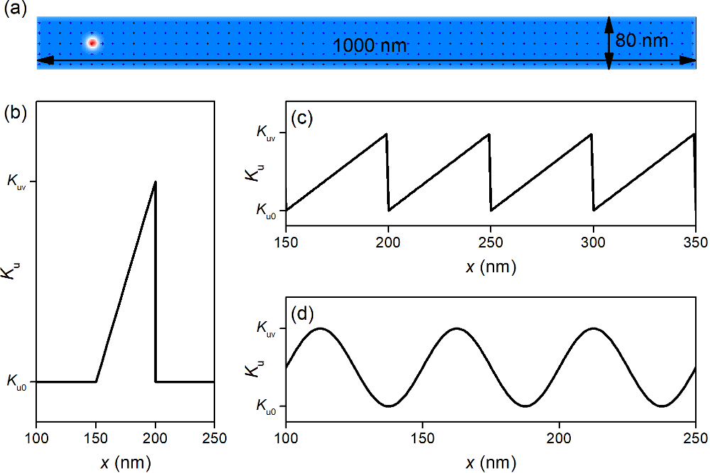
The simulation model is an ultrathin ferromagnetic nanotrack, , as shown in Fig. 1a. The micromagnetic simulations are performed with the Object Oriented MicroMagnetic Framework (OOMMF) donahue2010oommf . The dynamic of magnetization are described by Landau-Lifshitz-Gilbert LLG (LLG) equation, written as
| (1) |
where is the reduced magnetization , is the saturation magnetization. is the gyromagnetic ratio and is the damping coefficient. is the effective field including the contributions of Heisenberg exchange, Dzyaloshinskii-Moriya interaction (DMI), magnetic anisotropy and demagnetization field. The u can be defined as , is the reduced Plank constant, is the current density, is the spin Hall angle, is the atomic lattice constant, is the electron charge, is the vacuum permeability constant, is the thickness of the magnetic nanotrackwoo2017spin . is the direction of the spin polarization which is equal to . The model is discretized into tetragonal volume elements with the size of . The parameters for the micromagnetic simulation are adopted from Ref. wiesendanger2016nanoscale, : the saturation magnetization kA/m, the damping coefficient , the DMI constant mJ/m2, and the exchange constant pJ/m. In the simulation, the profile of the voltage-controlled magnetic anisotropy (VCMA) in the nanotrack are shown in Figs. 1b-d. For the simulation of the pinning/depinning states of the skyrmion, the PMA profile is shown in Fig. 1b. VCMA linearly varies from to and MJ/m3. For the simulation of the motion of skyrmion, two types of VCMA profile are considered, period wedge-shape and sinusoidal functions, as shown in Figs. 1c and 1d respectively. The function for the period wedge-shape profile is given as:
| (2) |
| (3) |
where is the period length , is the phase, and is the longitudinal coordinate. The period wedge-shape is given in the Eq. 2 and the sinusoidal function is given in the Eq. 3. The linear anisotropy profile and the sinusoidal function profile are given in the Figs. 1b and 1c.
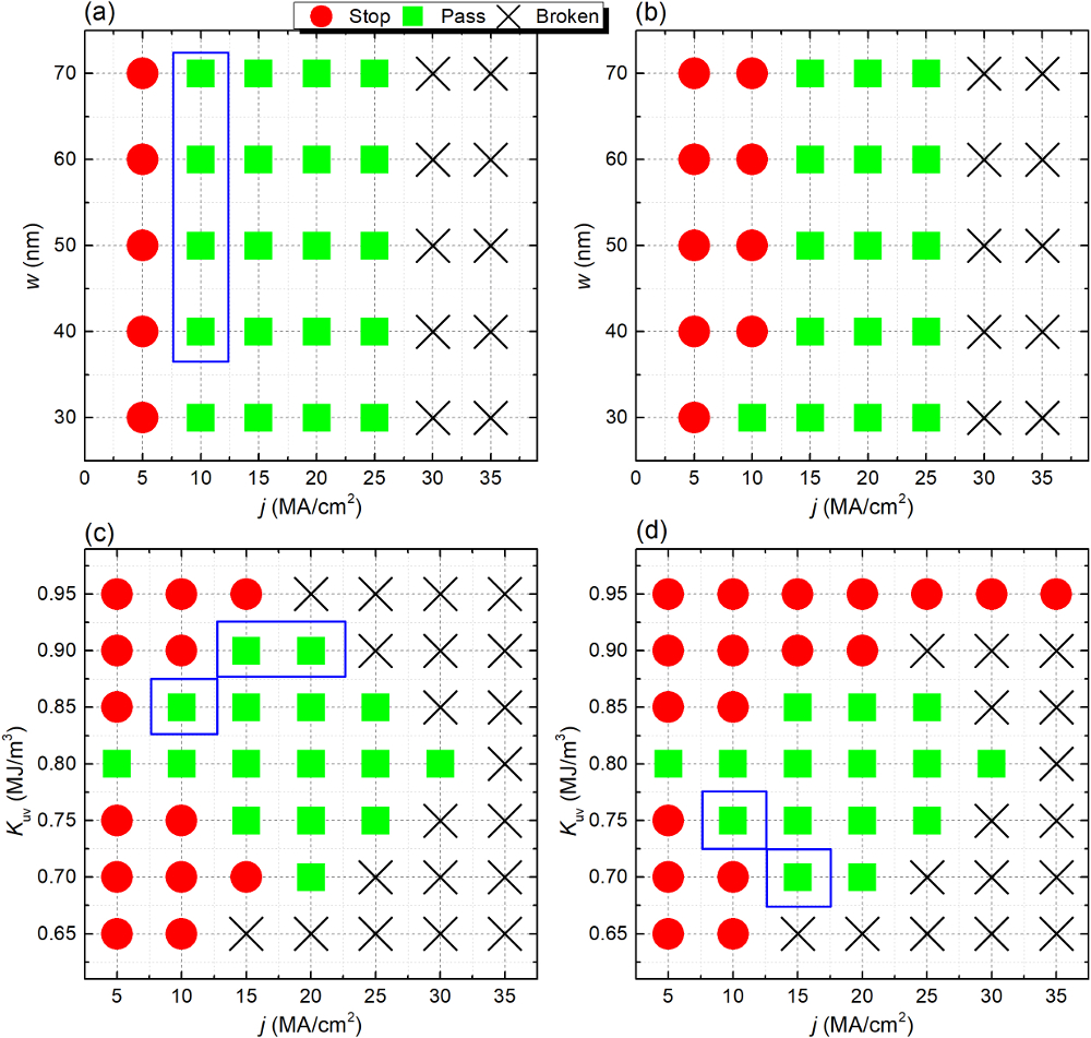
Fig. 2 shows the pinning/depinning states of isolate skyrmion driven by the spin current in a nanotrack with the PMA profile shown in Fig. 1b. Figures 2a and 2b show the effect of the width and the current density on the pinning/depinning states. Initially, the relaxed skyrmion is located at the left side of the VCMA region when the spin current is applied along axis. The skyrmion is not able to pass the VCMA region when the current density is smaller than MA/cm2 and pass the VCMA region when . The skyrmion will be destroyed when the current is larger than MA/cm2. When the spin current is applied along axis, the skyrmion is located at the right side of the VCMA region. Most states are the same to the corresponding results in Fig. 1a, except for the case of . For and , the skyrmion can pass the VCMA region when the current is applied along axis while it can not pass when the current is applied along axis. It means that the skyrmion can pass only in one direction, axis. The motion of skyrmion is unidirectional. The parameters corresponding to the unidirectional pass along axis are marked with blue box in Fig. 2a. Figures 2c and 2d show the effect of the VCMA and the current density on the pinning/depinning states. The results shows that the states is sensitive to the VCMA. The unidirectional behaviors also can be found. The parameters for the unidirectional pass along axis are marked with blue box in Fig. 2c and these for the unidirectional pass along axis are marked with blue box in Fig. 2d. The unidirectional behaviors shows that the voltage gate can be used to built skyrmion diode.
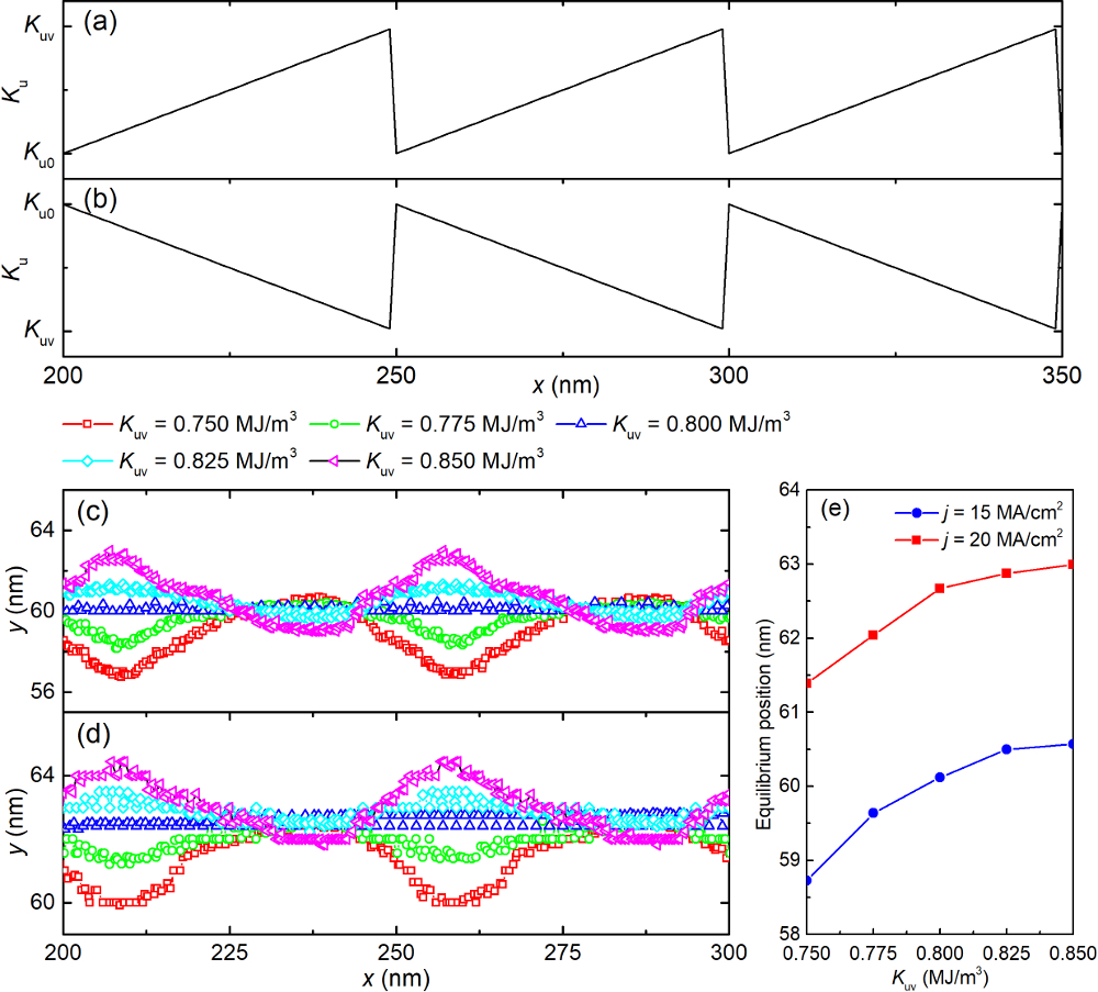
The skyrmion motion driven by the spin current in a magnetic nanotrack with the spatially dependence of VCMA is simulated. The VCMA is periodical repetition of a wedge-shape profile, as shown in Figs. 3a () and 3b (). Initially, the relaxed skyrmion is located at nm and nm. The trajectories of the skyrmion driven by the spin current () in the nanotrack with various are shown in Fig. 3c. For , a uniform perpendicular magnetic anisotropy in the nanotrack, the skyrmion shows a transverse motion towards to the upper edge resulted by the transverse force due to skyrmion Hall effect firstly jiang2016direct . When the transverse force and edge-skyrmion repulsive force are balanced, the skyrmion moves straightly du2015edge ; nii2015uniaxial ; jiang2015blowing . It can be seen that the skyrmion moves straightly at nm finally. For , the skyrmion moves in a periodical wavy trajectory with an equilibrium position at nm. Similar behaviors of the skyrmion are found when , and . It can be found that the equilibrium position increases with increasing , which is shown in Fig. 3e. Periodical wavy trajectories and similar dependence of the equilibrium position on can be also found in the case of , as shown in Fig. 3d. The equilibrium positions of the periodical wavy trajectories is larger compared to the case of .
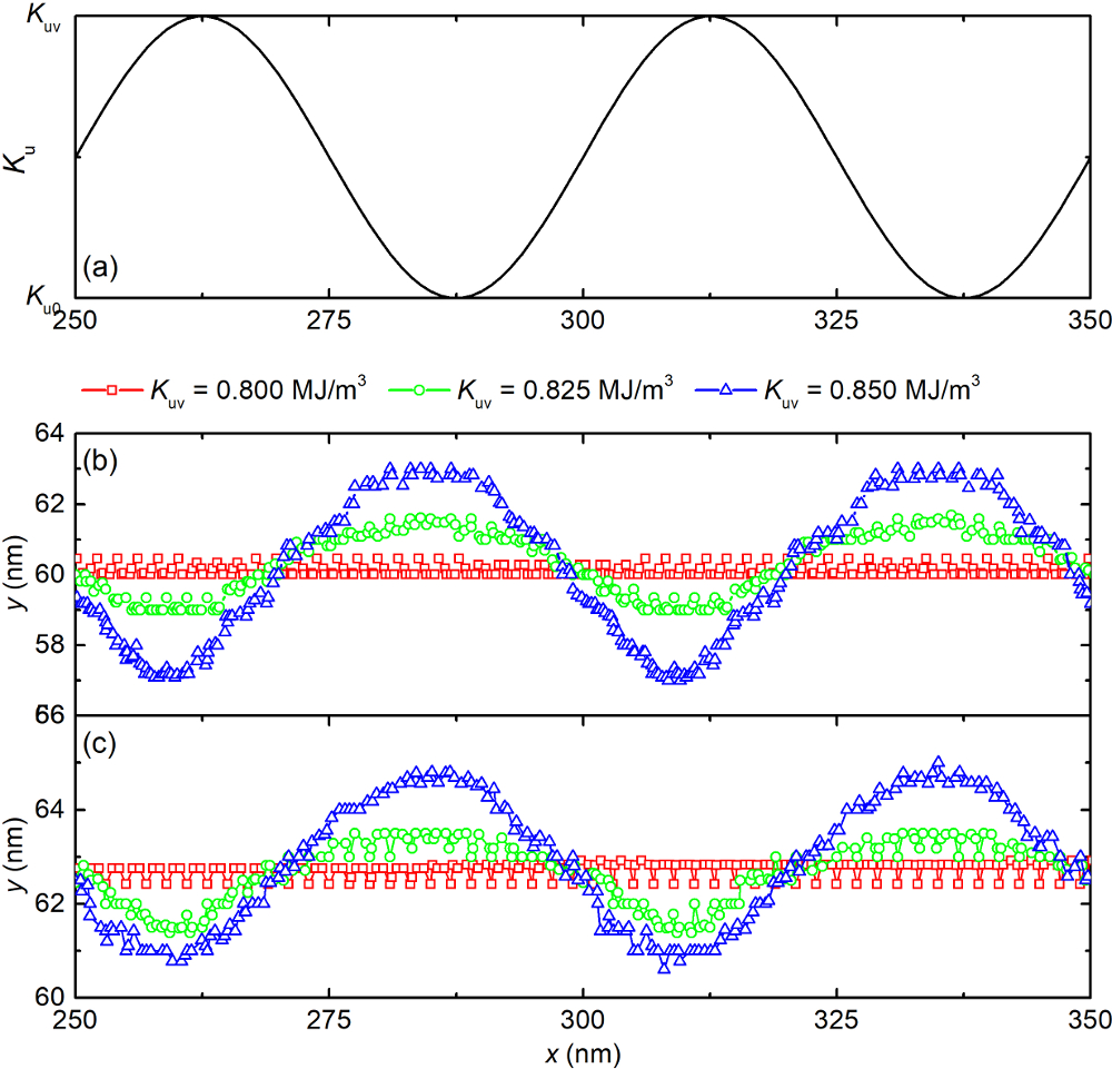
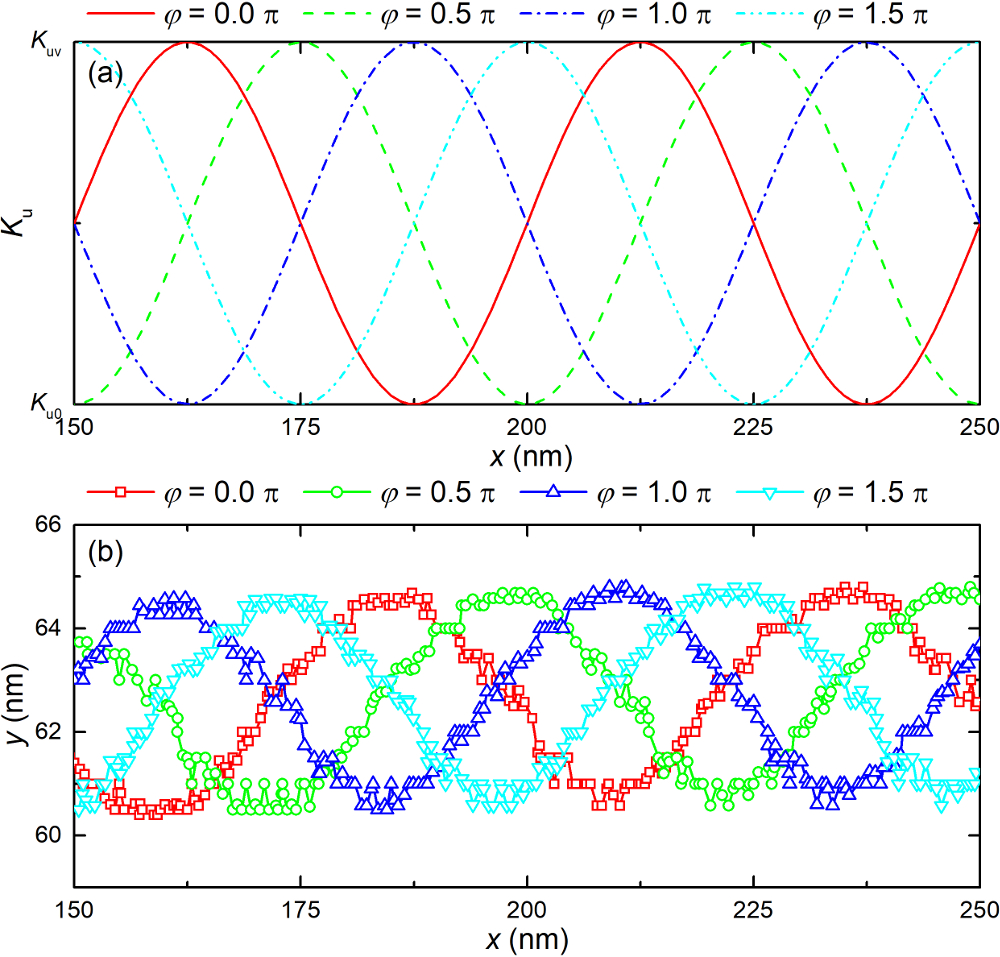
Figure 4 shows the trajectories of the skyrmion in a nanotrack with sinusoidal dependence of on the position . The profile of is shown in Fig. 4a. is the minimum and is the maximum. It can be found from Fig. 4b that the skyrmion moves in a sinusoidal trajectory when . Differently from the case of the wedge-shaped profile of , the equilibrium positions in direction for various are almost the same, nm. When the current density increases to , similar results can be found. Further, the effect of the phase also has been simulated and the results are shown in Fig. 5.
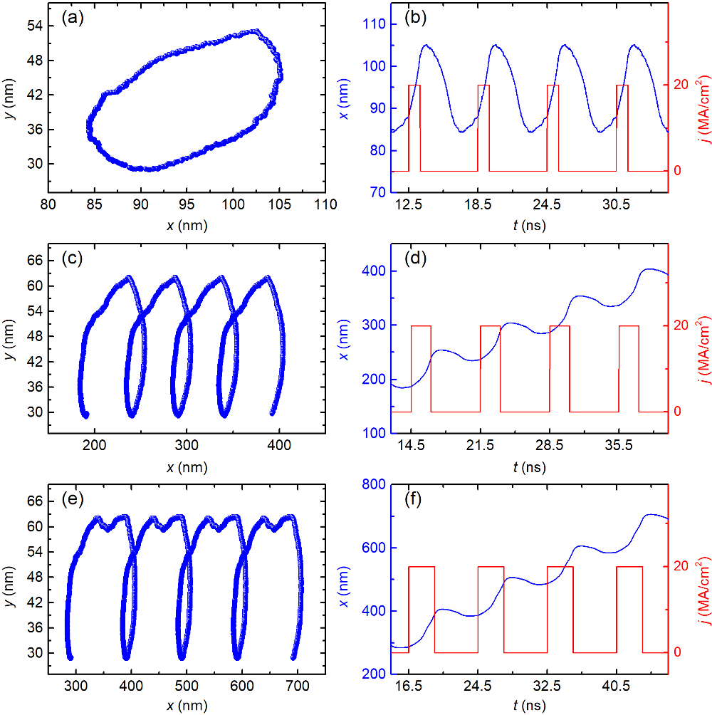
The motion of the magnetic skyrmion in the nanotrack with VCMA driven by the current pulse also be simulated. The initial position the skyrmion is nm which is the middle of a voltage gate. Figure 6 shows the motion of the skyrmion in the nanotrack with a periodical wedge-shaped profile with with the period length nm. The current density of the pulse is . The pulse is applied at ns. For one period of the current pulse , is the time interval applying the current and is the relax time without applying current. ns in the simulations. When ns, the skyrmion cannot pass the voltage gate and moves in a circle trajectory as shown in Figs. 6a and 6b. For ns, the trajectory of the skyrmion is shown in Fig. 6c. The time-dependence of the position in the direction and the current density are shown in Fig. 6d. At ns, the skyrmion is located at nm. After applying the pulse, nm at ns. Then the applied current is off. The skyrmion further relax to nm before the next pulse. The displacement of skyrmion is nm after a pulse is applied. For ns, Figs. 6e and 6f, one current pulse results in a displacement of nm.
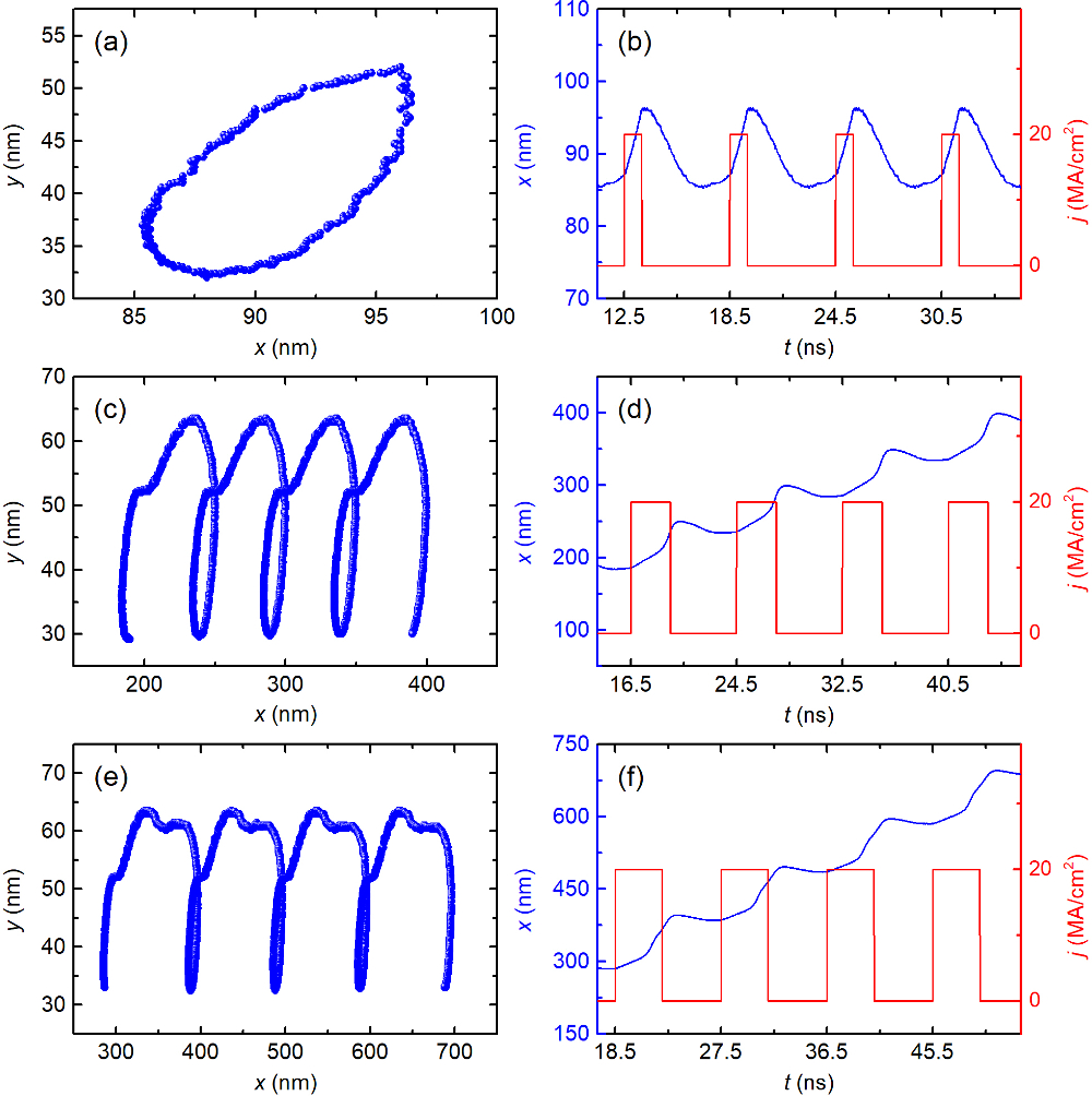
Figure 7 shows the results for the case of wedge-shaped with and the period length nm. The current density of the pulse is and the pulse is applied at ns with ns. In Figs. 7a and 7b, compared with the state with , the skyrmion can more easily pass the voltage gate. This state also has been explained in Fig. 2c. The skyrmion passes the first voltage gate and cannot pass the second voltage gate. Then the skyrmion moves in a circle trajectory. When the ns and 3 ns, the states is similar as Figs. 6c-f. The skyrmion pass one or two voltage gates are shown in Figs. 7c-f. In Figs. 7c and 7d, for ns, the skyrmion is located at nm when ns. After applying the pulse, skyrmion moves to nm. When the current is off, the skyrmion further relaxes to nm before the next pulse. The displacement of skyrmion is nm after a pulse is applied. For ns, as shown in Figs. 7e and 7f, one current pulse lead to a displacement of nm.
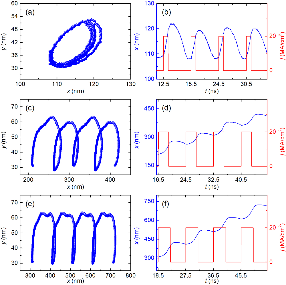
Figure 8 shows the motion of the skyrmion in the nanotrack with a sinusoidal function profile with with the period length nm. The trajectories of skyrmion with ns are shown in Figs. 8a and 8b. The skyrmion cannot pass the voltage gate and moves in a circle which is like Figs. 8a and 8b. For ns, the trajectory of the skyrmion is shown in Fig. 8c. The time-dependence of the position in direction and the current density are shown in Fig. 8d. At ns, the skyrmion is located at nm. After applying the pulse, nm at ns. Then the applied current is off. The skyrmion further relax to nm before the next pulse. The skyrmion moves with a pulse time ns is shown in Figs. 8e and 8f which one current pulse results in a displacement of nm. From Fig. 6 to Fig. 8, it can be seen that the model with multiple voltage gates can be used to realize high density racetrack memory device.
In this Letter, the skyrmion motion in a ferromagnetic nanotrack with single or multiple VCMA gates is studied. This work shows the trajectory and location of the skyrmion can be controlled by periodically located VCMA gates as well as the driving current pulse. The unidirectional motion of the skyrmion realized by the VCMA effect can be used to build the skyrmion-based one-way information channel and the skyrmion diode. Our results are useful for the design and development of the skyrmion-based spintronic devices.
Acknowledgements.
Y.X. acknowledges the support by the State Key Program for Basic Research of China (Grant Nos. 2014CB921101 and 2016YFA0300803), National Natural Science Foundation of China (Grant Nos. 61427812 and 11574137), Jiangsu NSF (No. BK20140054), Jiangsu Shuangchuang Team Program, and the UK EPSRC (EP/G010064/1). Y.Z. acknowledges the support by the National Natural Science Foundation of China (Grant No. 11574137) and Shenzhen Fundamental Research Fund (Grant No. JCYJ20160331164412545). G.P.Z. acknowledges the support by the National Natural Science Foundation of China (Grant Nos. 11074179 and 10747007), the Construction Plan for Scientific Research Innovation Teams of Universities in Sichuan (No. 12TD008). X.Z. was supported by JSPS RONPAKU (Dissertation Ph.D.) Program.References
- (1) S. Mühlbauer, B. Binz, F. Jonietz, C. Pfleiderer, A. Rosch, A. Neubauer, R. Georgii, and P. Böni, Science 323, 5916 (2009).
- (2) C. Pfleiderer, T. Adams, A. Bauer, W. Biberacher, B. Binz, F. Birkelbach, P. Böni, C. Franz, R. Georgii, M. Janoschek, F. Jonietz1, T. Keller, R. Ritz, S. Mühlbauer, W. Münzer, A. Neubauer, B. Pedersen, and A. Rosch, J. Phys.: Condens. Matter 22,16 (2010).
- (3) W. Münzer, A. Neubauer, T. Adams, S. Mühlbauer, C. Franz, F. Jonietz, R. Georgii, P. Böni, B. Pedersen, M.Schmidt, A. Rosch, and C. Pfleiderer, Phys. Rev. B 81, 041203 (2010).
- (4) X. Z. Yu, N. Kanazawa, Y. Onose, K. Kimoto, W. Z. Zhang, S. Ishiwata, Y. Matsui, and Y. Tokura, Nat. Mater. 10, 106-109 (2011).
- (5) S. Heinze, K. Von Bergmann, M. Menzel, J. Brede, A. Kubetzka, R. Wiesendanger, G. Bihlmayer, and S. Blügel, Nat. Phys. 7, 713 (2011).
- (6) S. Seki, X. Yu, S. Ishiwata, and Y. Tokura, Science 336, 198 (2012).
- (7) G. Chen, A. Mascaraque, A. T. N’Diaye, and A. K. Schmid, Appl. Phys. Lett. 106, 242404 (2015).
- (8) S. Do Yi, S. Onoda, N. Nagaosa, and J. H. Han, Phys. Rev. B 80,054416 (2009).
- (9) N. Nagaosa and Y. Tokura, Nat. Nanotech. 8, 899 (2013).
- (10) A. Fert, V. Cros, and J. Sampaio, Nat. Nanotech. 8, 152 (2013).
- (11) X. Yu, Y. Tokunaga, Y. Kaneko, W. Zhang, K. Kimoto, Y. Matsui, Y. Taguchi, and Y. Tokura, Nat. Commun. 5, 3198 (2014).
- (12) H. Du, J. P. DeGrave, F. Xue, D. Liang, W. Ning, J. Yang, M. Tian, Y. Zhang, and S. Jin, Nano Lett. 14, 2026 (2014).
- (13) H. Du, R. Che, L. Kong, X. Zhao, C. Jin, C.Wang, J. Yang, W. Ning, R. Li, C. Jin, X. Chen, J. Zang, Y. Zhang, M. Tian, Nat. Commun. 6, 8504 (2015).
- (14) W. Jiang, X. Zhang, G. Yu, W. Zhang, X. Wang, M. B. Jungfleisch, J. E. Pearson, X. Cheng, O. Heinonen, K. L. Wang, Y. Zhou, A. Hoffmann, and S. G. E. te Velthuis, Nat. Phys. 13, 162 (2017).
- (15) W. Jiang, P. Upadhyaya, W. Zhang, G. Yu, M. B. Jungfleisch, F. Y. Fradin, J. E. Pearson, Y. Tserkovnyak, K. L. Wang, O. Heinonen, S. G. E. te Velthuis, A. Hoffmann, Science 349, 283 (2015).
- (16) Y. Nii, T. Nakajima, A. Kikkawa, Y. Yamasaki, K. Ohishi, J. Suzuki, Y. Taguchi, T. Arima, Y. Tokura, and Y. Iwasa, Nat. Commun. 6, 8539 (2015).
- (17) X. Zhang, Y. Zhou, M. Ezawa, G. Zhao, and W. Zhao, Sci. Rep. 5, 11369 (2015).
- (18) J. Wang, X. Zhang, X. Lu, J. Zhang, Y. Yan, ,H. Ling,J. Wu,Y. Zhou, and Y. Xu, Appl. Phys. Lett. 111, 072401 (2017).
- (19) X. Zhang, M. Ezawa, and Y. Zhou, Sci. Rep. 5, 9400 (2015).
- (20) X. Zhang, G. Zhao, H. Fangohr, J. P. Liu, W. Xia, J. Xia, and F. Morvan, Sci. Rep. 5, 7643 (2015).
- (21) Y. Liu, N. Lei, W. Zhao, W. Liu, A. Ruotolo, H.-B. Braun, and Y. Zhou, Appl. Phys. Lett. 111, 022406 (2017).
- (22) Y. Nakatani, M. Hayashi, S. Kanai, S. Fukami, and H. Ohno, Appl. Phys. Lett. 108, 152403 (2016).
- (23) J. Franken, H. Swagten, and B. Koopmans, Nat. Nanotech. 7, 499(2012).
- (24) L. Sánchez-Tejerina, Ó. Alejos, and E. Martínez, V. Raposo, arXiv preprint arXiv:1705.00905 (2017).
- (25) M. J. Donahue and D. G. Porter, OOMMF User Guide, Version 1.0, Interagency Report NIST IR 6376, Gaithersburg, MD (1999).
- (26) S. Woo, K. M. Song, H.-S. Han, M.-S. Jung, M.-Y. Im, K.-S. Lee, K. S. Song, P. Fischer, J.-I. Hong, J. W. Choi, B. -C. Min, H. C. Koo, J. Chang, arXiv preprint arXiv:1705.09019 (2017).
- (27) R. Wiesendanger, Nat. Rev. Mater. 1, 16044 (2016).