Electric field vector mapping of guided ionization waves at atmospheric pressure
Abstract
In this study, the dynamic of guided ionization wave (IW) generated by an atmospheric pressure plasma jet (APPJ) device in plasma gun configuration is experimentally investigated. The present work focuses on the properties of the intense electric field (EF) driving the IW. Taking advantages of APPJs to produce guided and reproducible IWs, the induced EF vector is characterized spatially and temporally along the direction of propagation. With this approach, EF vector mapping of guided IWs have been measured and documented for the first time. In the first part, the propagation within a glass tube of the first IW is investigated. Under the present conditions, a second guided IW is observed and propagates, leading to the formation of a guided streamer. The EF due to transient charge deposited on the wall surface is observed, particularly at the end of the tube. In the second part, one reports on the EF vector mapping under a dielectric substrate in contact with guided IWs. EF strength up to has been measured and corroborates prior results from predictive numerical simulations. Intriguing configurations of the EF lines will be of significant interest to validate theoretical models in order to refine the non-equilibrium plasma chemistry kinetics. Furthermore, this preliminary work provides important insights into various applications involving IW driven discharges such as liquid activation, environmental treatments, plasma medicine, active flow control and plasma agriculture.
Introduction
Room temperature atmospheric pressure plasma sources have been massively developed over the past decade aiming at various applications in the fields of biology and medicine [1, 2], environmental science and liquid activation [3, 4], surface activation and material processing [5, 6] and active flow control [7].
The uniqueness of non-thermal plasma combining different forms of energy – electric, ionization, chemical, radiant and thermal – yields a rich reactive chemistry [8].
The production of reactive species depends strongly on the type of plasma source [9].
Among those, cold atmospheric pressure plasma jet (APPJ) offers the advantages of a cheap construction, a simple design and flexibility to integrate into industrial processes.
A large amount of electrical configurations and geometries have been reported in the literature [10].
Up-to-date additional technological aspects have been summarized in [11].
In most APPJ devices, the plasma formation is due to the propagation of guided ionization waves (IW) also named in the literature as pulsed atmospheric pressure plasma streams (PAPS) [12] or more commonly guided streamer [13].
Operating at atmospheric pressure, atomic gases such as helium, argon or neon are used mainly for their chemical neutrality and ionization properties.
The morphology of guided IW depends on the gas and admixtures (typically N2 or O2), producing a rather diffuse or filamentary discharge [14].
The mechanism of guided IW has been extensively reviewed in [15] from a theoretical and an experimental point of view.
Briefly, with the presence of high external electric field (EF), atoms and molecules of the medium are ionized by electron impacts leading to the formation of a space charge.
The density of volumetric charges contributes to the enhancement of the local EF in the front exceeding the external applied EF and allowing for the propagation of the IW.
Guided IW have the additional features of a predictable and reproducible direction propagation of the bright ionization front containing highly energetic electrons and photons being favorable for the creation of a darker – partially – ionized channel.
The intense light emission of the guided IW front was observed first using high-speed photographs, where the term “plasma bullet” is suggested as a phenomenological description [16].
Later, the evidence of the front is reported with the first measurement of EF strength up to in guided IW in helium, by means of Stark polarization emission spectroscopy [17] and confirms prior results of numerical simulations [18].
Recent studies involving a similar plasma source have been carried out to characterize the EF resulting from the space charge ahead of the IW and before the first light coming from the ionization front [19].
In [20], the same group proposed a thoroughgoing numerical and experimental study where a successful agreement of the temporal evolution of the EF is found with the theoretical model.
Getting experimental insight into the EF resulting from guided IW is of high interest for the plasma community and beyond: towards large domains of applications.
Indeed, the electron temperature is strongly related to the EF and plays a key role in the ionization mechanisms as well as the global kinetic of the plasma chemistry.
Furthermore, the EF in guided IW is not uniform and is also time dependent which requires temporally and spatially resolved EF investigations also addressed as a future challenge in a recent review article [15].
In this paper, the authors report on an experimental study dealing with the characterization of the EF vector mapping of a guided IW in helium at atmospheric pressure.
The work is centered around the simultaneous investigation of two orthogonal components of the EF space and time resolved.
The aspects documented here are twofold.
-
•
On the one hand, one focuses on the EF in the vicinity of the guided IW to prevent any perturbation induced by the measurement technique, and thus to study quantitatively the dynamic of the vector EF during the propagation.
-
•
On the other hand, the EF properties of a guided IW in contact with a dielectric material will be presented to unveil the interaction between the plasma and a treated substrate.
Experimental setup
In this work, guided IW are generated using a cold helium APPJ so-called plasma gun (PG) [12].
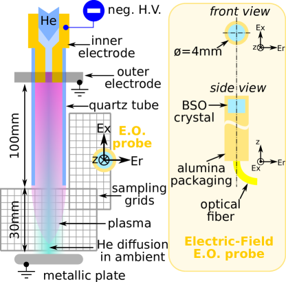
In outlines, the PG consists of a coaxial dielectric barrier discharge design shown in figure 1.
A concentric assembly involves a pair of electrodes mounted on a thick and inner diameter quartz tube.
The powered electrode fits into the tube and allows one to inject helium through a channel drilled along the axis.
The grounded ring electrode is set on the outer surface of the tube and aligned with the tip of the powered electrode.
The helium flow rate is set at at standard conditions of temperature and pressure.
The inner electrode is connected to a symmetric H.V. pulsed generator.
In this work, repetitive negative pulses of FWHM and fall time at the frequency of are used exclusively.
The H.V. negative waveform is measured on the electrode and plotted in figure 2.
The choice of the negative polarity is twofold: from the emission of the light, the plasma seems homogeneous in volume and the gas flow pattern exiting the tube remains laminar in these conditions [19, 21].
This contributes to the stability of the rectilinear direction of the guided IW which propagates into the helium channel expanding in the ambient air.
The partially ionized gas outside the quartz tube is the so-called plasma plume.
Most of the geometries of APPJs cannot provide a fixed electric potential in the vicinity of the plasma plume which makes APPJs very sensitive to the electrical composition in its surrounding.
Thus, the substrate of a treated sample is an important element of the electrical circuit of APPJs.
Therefore, a conductive plate connected to the ground is placed away from the tube exit to fix a known electric potential in the vicinity of the plasma plume.
It is important to mentioned that the guided IW – and thus the plasma plume – does not reach its surface, preventing a direct electric connection.
The EF diagnostic is carried out with a customized pigtailed electro-optic sensor (E.O.) commercialized by Kapteos s.a.s. and detailed in figure 1.
This technology applied recently to plasmas [22] is based on the Pockels effect.
The sensor is made of a cylindrical isotropic birefringent crystal probed with a laser beam guided through a fiber optic [23].
Depending on the variation of the light polarization induced by the external EF, the system is able to measure simultaneously the EF amplitude in two orthogonal directions of space.
Although this method is not suitable for the measurement of static EF, the instrument is able to detect transient EF from tens of up to with a time resolution of and a spatial resolution of the crystal size ().
To perform a 2D characterization of the EF, the position in space the E.O. sensor is adjusted with a X-Y motorized translation stage.
As shown in figure 1, axis of the E.O. sensor is parallel to the longitudinal axis of the PG while orthogonal axis, , is collinear with the radius of the tube.
Two sampling domains are defined: one on the right side of the PG – along the tube – in order to characterize the EF of the guided IW without any disturbance from the probe.
A second domain is in the gap between the exit of the tube and the metallic plate.
In the later condition, the E.O. probe is directly in contact with the plasma plume and acts as a dielectric treated substrate.
In each node of the sampling grid, the time evolution of longitudinal (Ex) and radial (Er) EF is measured simultaneously.
Hence, one defines the EF strength by .
Results and discussion
An example of the time evolution of both Ex and Er are presented in figure 2.
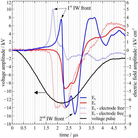
The set of curves in continuous line are related to this study while the set drawn in dash line refers to prior investigations correlating successfully experimental and numerical simulations results [20].
Focusing first on Ex signals, the front of the IW is clearly identified as a sharp peak of about with an amplitude of several as already reported in [19, 20, 21].
A time delay between both signals is found around due to the two different vertical positions of the measurement.
The propagation velocity of the IW front is estimated around which is in agreement with prior studies [20].
Shortly after the IW front passed, one notices a quick rise of Er resembling a square pulse of FWHM with an amplitude between and .
The reason of this intense radial EF is explained by the creation of a – partially – conductive channel formed within the tube after the propagation of the IW front.
Due to a significant density of charges and the direct contact of the plasma channel with the powered electrode, the square feature in the Er signals result from the dynamic of the H.V. pulse.
The electric potential is thus transferred from the inner electrode to the plasma column from where results the intense radial EF.
Depending on the electrical configuration of the PG, the dynamic of the voltage pulse can have a significant influence on Ex [21].
Indeed, in case of a PG free of grounded ring electrode, one can observe a negative peak occurring at which corresponds exactly on time with the applied voltage imposed by the generator and rising to the ground potential.
This negative peak of Ex is drastically enhanced (down to ) for a PG reactor equipped with a grounded electrode.
Furthermore, on the same signal, a global minimum of Ex is seen at i.e. after the IW front.
The latter results from the second IW front propagation as discussed in [24].
Figure 3 presents a sequence of EF vector mapping sampled on the right hand side of a PG.
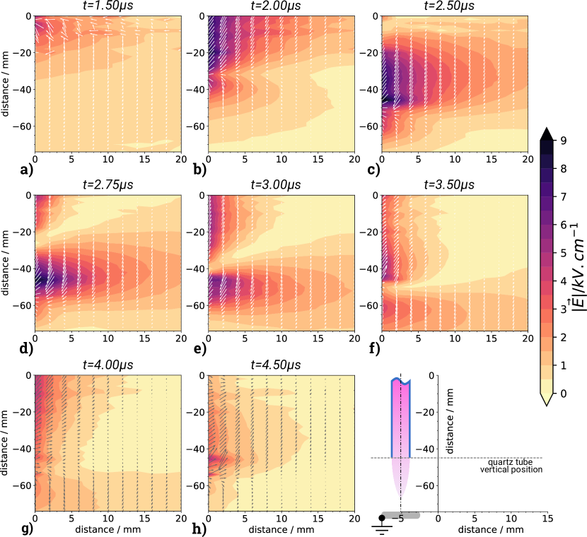
The data shown in those maps are time dependent signals of Ex and Er – such as shown in figure 2 – recorded for different nodes of the sampling grid.
By processing the data set, the vector field can be displayed, revealing the EF lines together with the EF strength.
The direct visualization of the IW front is depicted in figure 3a) with a strong EF gradient and the vectors pointing toward the front.
The direction of the EF results from the negative charge – mainly electron due to their higher mobility – ahead of the IW.
At , the H.V. pulse reaches its minimum at imposed to the plasma channel.
Figure 3b) shows the EF resulting from the negative charge attached to the inner surface of the tube balancing the positive space charge which bounds the plasma column [25].
This is sustained as long as the level of the applied voltage is not back to the ground potential.
Thus an intense EF from the plasma column extend up to and giving rise to a negative (anode-directed) guided streamer [26].
The propagation of the IW starts to slow down around , i.e when the electric potential is at the minimum.
Then, the latter begins to raise up, leading to a fast increase of the electric potential of the inner electrode which stops the propagation of the first IW as shown in figure 3c).
The EF strength drops quickly as well as the electron kinetics which will affects the plasma properties, for instance He metastable densities [24].
The localized intense EF at corresponds to the end of the tube and indicates a significant attachment of transient charge distributed around the tube section.
Intuitively, the magnitude of the induced EF is dependent on the shaping of the tube edge and the density of charge.
On figure 3d), one notices an enhancement of charge and the resulting EF measured over several tens of .
The direction of the EF indicates the presence of negative charge.
Back diffusion of ambient air into the He gas flow was already observed, particularly with the emission of excited atomic oxygen [27, 28].
According to [25], O2 are the dominant negative ions at the exit of the tube due to a smaller Te being favorable to electrons to attach to O2.
Although the technique involved in this study cannot provide any information about static charge, deposited charges have been recently investigated [29, 30].
In [30], the authors estimated the loss within the tube around .
The fast rise of the electrode potential induces a second IW front propagating with a strong EF polarized in the opposite direction with the first IW.
The separation between both IW is characterized by a sharp gradient of EF creating a gap where the value of the EF strength is damped close to .
At , the applied potential imposed by the generator is distributed along the conductive channel after the propagation of the second IW.
Consequently, the EF direction reverses due to an electrode potential being increased compared to the charge residual of the first IW and the charging of the wall tube by positive charge [31].
This brutal flipping of the EF influences the ionization dynamic and the electron kinetic which govern the whole plasma chemistry kinetic.
The propagation of the second IW within the tube is shown in figure 3e).
The contribution of the negative charge at the tube exit to weaken significantly the EF of the second IW is clearly identified.
As the result, the shaping of the tube exit must play a key role in the dynamic of the IW propagation and the plasma dynamics due to the presence of a local EF of tens of .
The plasma column is sustained until the applied voltage returns back to the ground potential.
The positive rise induces the propagation of the second IW leading to the formation of a positive (cathode-directed) guided streamer [26].
Indeed, the direction of the EF vectors of the plasma channel indicates a positive charging of the tube wall and confirms prior predictive numerical work regarding positive guided streamer mechanism [31].
Last but not least, the EF strength is measured to be higher in the column of the negative streamer compared to the positive streamer which is in agreement with several predictive models [32, 33].
APPJs are also driven with AC H.V. power supply where the existence of a second IW front may be questioned.
According to [34], with slow AC regime, a IW is ignited at each half-period.
Further investigations are necessary to identify the role of the frequency and the H.V. amplitude for the generation of a second guided IW.
The second part of this study focuses on the EF vectors in the plasma plume region.
In contrast with the previous experiment, the E.O. probe is now being directly in contact with the IW during scanning operations.
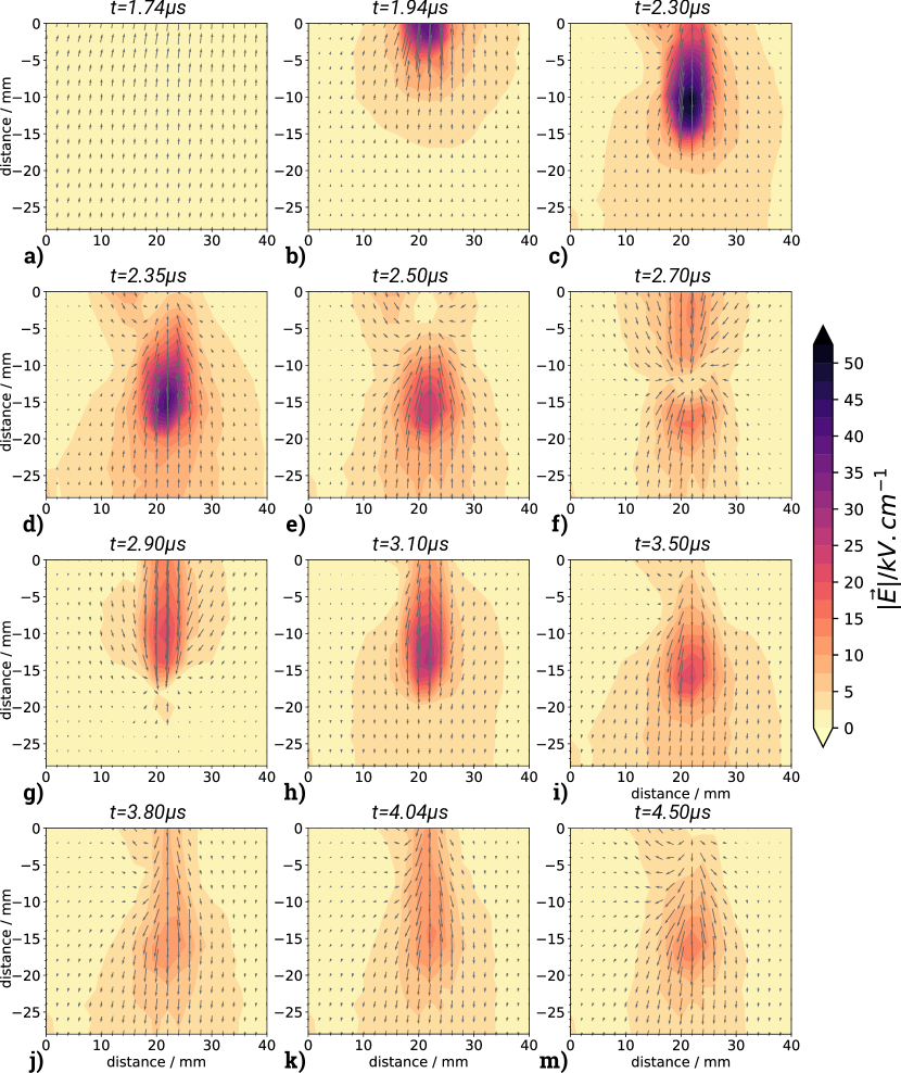
Sequences of EF vectors maps are presented in figure 4.
Depending on the position of the E.O. probe, the plasma plume can impinge on the alumina surface protecting the BSO crystal.
In this case, it is important to clarify that the interpretation of the results differs from the previous set.
Indeed, the EF strength values shown in figure 4 are not within the IW front, but correspond to the EF intensity under a dielectric surface – of a relative permittivity (), – touching the plasma plume.
However, the directions of the EF vectors are assumed to do not be affected by the surface.
In figure 4a), the EF vectors is polarized vertically, directed toward the negative charge ahead of the IW front which is propagating into the tube.
At , the IW front has already exited the tube and propagates into the ambient.
An intense EF expands within a symmetric volume of large and a maximum strength up to .
Such extreme EF measured under the dielectric layer results from the interaction of the plasma with the surface.
In the present case, the relatively low , the continuity of the electric displacement vector, allows for an effective penetration of the longitudinal EF of the IW front through the surface.
The EF strength is enhanced due to the transient charge deposited on top of the surface.
A recent numerical work on plasma jet interacting with various dielectric and metal surfaces documents EF strength value in good agreement with the present experiment [25].
The computed value under the surface of ranges from .
Although in the current study, it is not possible to untangle the contribution of the IW front and the transient charge to the EF strength, the maximum value is reached around , when the first IW front exits the tube.
In figure 4c) and d), the applied voltage pulse has passed its minimum amplitude to start the rising slope which leads to a separation of the first IW as previously mentioned.
Interestingly, the EF direction in the vicinity of the tube exit describes a curl which is attributed to the presence of negative charge, such as O2 at the tip of the glass tube [25].
The rise up of the applied voltage imposed to the plasma channel implies a flip of the EF and the creation of a second IW shown in figure 4e).
At this time (), an isolated EF source up to is observed at being generated by negative charge stored on the dielectric surface.
The recombination of the charges leads to a significant decrease of the EF strength while the second IW propagates.
The dynamic of both processes gives rise to an intriguing configuration of the EF lines as shown in figure 4f).
The map reveals a head-to-tail EF configuration separated by a gap at where the EF induced by the second IW and the surface charge compensate each other.
It is anticipated that such EF feature must have a significant influence on the ionization mechanism and chemical kinetic of the plasma.
The recombination of the charge on top of the surface by the second IW allows the latter to propagate further.
At , the EF is polarized vertically, flipped upside down, revealing the path of the ionized channel produced by the IW propagation.
The structure of the EF and the magnitude up to evidences the existence of a second IW propagating in to the mixture of helium and air.
The charging of the surface significantly contributes to the EF strength after the applied voltage returned back to the ground potential.
Knowing the key role of the EF the production mechanism of reactive species, it is assumed that the whole plasma chemistry must be strongly affected in case of liquid substrate in contact with IW.
Concluding remarks
Focusing on the essence of APPJs –guided IWs–, this manuscript reports for the first time on experimental EF vector characterization.
Measurements performed with a unique technology based on E.O. probe allow us to produce EF vector mapping of guided IWs.
Propagation velocities of the IW are in agreement with prior works based on the investigation of light emission.
It is shown that APPJs powered with a H.V. pulse generator initiate the propagation of two consecutive guided IW with opposite EF vector direction.
It is discussed that the time scale of the H.V. pulse and the remaining ionization of the channel created by the first guided IW are crucial parameters for the generation of a second guided IW.
The transient EF due to the attachment of charge on the wall has been identified and a specific attention must be paid to the shaping of the section of the tube.
EF vector mapping measured under a dielectric surface in contact with the IW brings new insights into the EF lines complexity driving the electron kinetic and therefore the global non-equilibrium chemistry.
A maximum of is measured under the dielectric surface.
The dynamic of the first IW is consistent non-intrusive measurements although the presence of a dielectric substrate in contact with the IW implies a change of the electric properties.
The evidence of a second guided IW is documented and unveils an intriguing head-to-tail configuration of the EF vector direction.
This preliminary study opens new ways to investigate experimentally EF induced by guided IWs and derived plasma devices such as APPJs. A plethora of applications will benefit from EF vector characterization to understand and to optimize plasma sources and processes, particularly in the field of plasma liquid interaction, surface modification, plasma medicine and agriculture including plasma cell interactions.
Acknowledgment
The author would like to thank X. Damany, J. M. Pouvesle and E. Robert for the continuous encouragement and general support, making this work possible.
S. Dozias is acknowledged for the electronic engineering and technical support.
Data and graphs have been exclusively processed with open-source libraries SciPy, NumPy [35], Veusz and Matplotlib [36].
References
- von Woedtke et al. [2013] Th. von Woedtke, S. Reuter, K. Masur, and K.-D. Weltmann. Plasmas for medicine. Physics Reports, 530(4):291–320, sep 2013. 10.1016/j.physrep.2013.05.005. URL http://dx.doi.org/10.1016/j.physrep.2013.05.005.
- Graves [2014] David B. Graves. Low temperature plasma biomedicine: A tutorial review. Physics of Plasmas, 21(8):080901, aug 2014. 10.1063/1.4892534. URL http://dx.doi.org/10.1063/1.4892534.
- Foster et al. [2012] John Foster, Bradley S. Sommers, Sarah Nowak Gucker, Isaiah M. Blankson, and Grigory Adamovsky. Perspectives on the interaction of plasmas with liquid water for water purification. IEEE Transactions on Plasma Science, 40(5):1311–1323, may 2012. 10.1109/tps.2011.2180028. URL http://dx.doi.org/10.1109/tps.2011.2180028.
- Bruggeman et al. [2016] P J Bruggeman, M J Kushner, B R Locke, J G E Gardeniers, W G Graham, D B Graves, R C H M Hofman-Caris, D Maric, J P Reid, E Ceriani, D Fernandez Rivas, J E Foster, S C Garrick, Y Gorbanev, S Hamaguchi, F Iza, H Jablonowski, E Klimova, J Kolb, F Krcma, P Lukes, Z Machala, I Marinov, D Mariotti, S Mededovic Thagard, D Minakata, E C Neyts, J Pawlat, Z Lj Petrovic, R Pflieger, S Reuter, D C Schram, S Schröter, M Shiraiwa, B Tarabová, P A Tsai, J R R Verlet, T von Woedtke, K R Wilson, K Yasui, and G Zvereva. Plasma–liquid interactions: a review and roadmap. Plasma Sources Science and Technology, 25(5):053002, sep 2016. 10.1088/0963-0252/25/5/053002. URL http://dx.doi.org/10.1088/0963-0252/25/5/053002.
- Kim et al. [2016] Kyong Nam Kim, Seung Min Lee, Anurag Mishra, and Geun Young Yeom. Atmospheric pressure plasmas for surface modification of flexible and printed electronic devices: A review. Thin Solid Films, 598:315–334, jan 2016. 10.1016/j.tsf.2015.05.035. URL http://dx.doi.org/10.1016/j.tsf.2015.05.035.
- Penkov et al. [2015] Oleksiy V. Penkov, Mahdi Khadem, Won-Suk Lim, and Dae-Eun Kim. A review of recent applications of atmospheric pressure plasma jets for materials processing. Journal of Coatings Technology and Research, 12(2):225–235, jan 2015. 10.1007/s11998-014-9638-z. URL http://dx.doi.org/10.1007/s11998-014-9638-z.
- Moreau [2007] Eric Moreau. Airflow control by non-thermal plasma actuators. Journal of Physics D: Applied Physics, 40(3):605–636, jan 2007. 10.1088/0022-3727/40/3/s01. URL http://dx.doi.org/10.1088/0022-3727/40/3/s01.
- Graves [2012] David B Graves. The emerging role of reactive oxygen and nitrogen species in redox biology and some implications for plasma applications to medicine and biology. Journal of Physics D: Applied Physics, 45(26):263001, jun 2012. 10.1088/0022-3727/45/26/263001. URL http://dx.doi.org/10.1088/0022-3727/45/26/263001.
- Fridman [2008] Alexander Fridman. Plasma Chemistry. Cambridge University Press, July 2008. ISBN 9780511546075.
- Lu et al. [2012] X Lu, M Laroussi, and V Puech. On atmospheric-pressure non-equilibrium plasma jets and plasma bullets. Plasma Sources Science and Technology, 21(3):034005, apr 2012. 10.1088/0963-0252/21/3/034005. URL http://dx.doi.org/10.1088/0963-0252/21/3/034005.
- Winter et al. [2015] J Winter, R Brandenburg, and K-D Weltmann. Atmospheric pressure plasma jets: an overview of devices and new directions. Plasma Sources Science and Technology, 24(6):064001, oct 2015. 10.1088/0963-0252/24/6/064001. URL http://dx.doi.org/10.1088/0963-0252/24/6/064001.
- Robert et al. [2012] E Robert, V Sarron, D Riès, S Dozias, M Vandamme, and J-M Pouvesle. Characterization of pulsed atmospheric-pressure plasma streams (PAPS) generated by a plasma gun. Plasma Sources Science and Technology, 21(3):034017, may 2012. 10.1088/0963-0252/21/3/034017. URL http://dx.doi.org/10.1088/0963-0252/21/3/034017.
- Boeuf et al. [2013] J-P Boeuf, L L Yang, and L C Pitchford. Dynamics of a guided streamer (“plasma bullet”) in a helium jet in air at atmospheric pressure. Journal of Physics D: Applied Physics, 46(1):015201, jan 2013. 10.1088/0022-3727/46/1/015201. URL http://dx.doi.org/10.1088/0022-3727/46/1/015201.
- Hofmann et al. [2012] S. Hofmann, A. Sobota, and P. Bruggeman. Transitions between and control of guided and branching streamers in DC nanosecond pulsed excited plasma jets. IEEE Transactions on Plasma Science, 40(11):2888–2899, Nov 2012. 10.1109/TPS.2012.2211621. URL http://dx.doi.org/10.1109/TPS.2012.2211621.
- Lu et al. [2014] X. Lu, G.V. Naidis, M. Laroussi, and K. Ostrikov. Guided ionization waves: Theory and experiments. Physics Reports, 540(3):123–166, jul 2014. 10.1016/j.physrep.2014.02.006. URL http://dx.doi.org/10.1016/j.physrep.2014.02.006.
- Teschke et al. [2005] M. Teschke, J. Kedzierski, E.G. Finantu-Dinu, D. Korzec, and J. Engemann. High-speed photographs of a dielectric barrier atmospheric pressure plasma jet. IEEE Transactions on Plasma Science, 33(2):310–311, apr 2005. 10.1109/tps.2005.845377. URL http://dx.doi.org/10.1109/tps.2005.845377.
- Sretenović et al. [2011] Goran B. Sretenović, Ivan B. Krstić, Vesna V. Kovačević, Bratislav M. Obradović, and Milorad M. Kuraica. Spectroscopic measurement of electric field in atmospheric-pressure plasma jet operating in bullet mode. Applied Physics Letters, 99(16):161502, oct 2011. 10.1063/1.3653474. URL http://dx.doi.org/10.1109/tps.2012.2219077.
- Naidis [2010] G V Naidis. Modelling of streamer propagation in atmospheric-pressure helium plasma jets. Journal of Physics D: Applied Physics, 43(40):402001, sep 2010. 10.1088/0022-3727/43/40/402001. URL http://dx.doi.org/10.1063/1.3576940.
- Robert et al. [2015] E. Robert, T. Darny, S. Dozias, S. Iseni, and J. M. Pouvesle. New insights on the propagation of pulsed atmospheric plasma streams: From single jet to multi jet arrays. Physics of Plasmas, 22(12):122007, dec 2015. 10.1063/1.4934655. URL http://dx.doi.org/10.1063/1.4934655.
- Bourdon et al. [2016] A Bourdon, T Darny, F Pechereau, J-M Pouvesle, P Viegas, S Iséni, and E. Robert. Numerical and experimental study of the dynamics of as helium plasma gun discharge with various amounts of N2admixture. Plasma Sources Science and Technology, 25(3):035002, mar 2016. 10.1088/0963-0252/25/3/035002. URL http://dx.doi.org/10.1088/0963-0252/25/3/035002.
- Darny [2016] Thibault Darny. Étude de la production des espèces réactives de l’oxygène et de l’azote par décharge Plasma Gun à pression atmosphérique pour des applications biomédicales. phdthesis, Université d’Orléans, June 2016.
- Gaborit et al. [2014a] G. Gaborit, S. Reuter, S. Iseni, and L. Duvillaret. Cold Plasma Diagnostic Using Vectorial Electrooptic Probe. In 5th International Conference on Plasma Medicine (ICPM5), Nara, Japan, 18-23 May 2014a. 10.13140/RG.2.2.12378.13768. URL http://dx.doi.org/10.13140/RG.2.2.12378.13768.
- Gaborit et al. [2014b] Gwenael Gaborit, Pierre Jarrige, Frederic Lecoche, Jean Dahdah, Eric Duraz, Christophe Volat, and Lionel Duvillaret. Single shot and vectorial characterization of intense electric field in various environments with pigtailed electrooptic probe. IEEE Transactions on Plasma Science, 42(5):1265–1273, may 2014b. 10.1109/tps.2014.2301023. URL http://dx.doi.org/10.1109/tps.2014.2301023.
- Darny et al. [2017] T Darny, J-M Pouvesle, V Puech, C Douat, S Dozias, and Eric Robert. Analysis of conductive target influence in plasma jet experiments through helium metastable and electric field measurements. Plasma Sources Science and Technology, 26(4):045008, mar 2017. 10.1088/1361-6595/aa5b15. URL http://dx.doi.org/10.1088/1361-6595/aa5b15.
- Norberg et al. [2015] Seth A. Norberg, Eric Johnsen, and Mark J. Kushner. Helium atmospheric pressure plasma jets touching dielectric and metal surfaces. Journal of Applied Physics, 118(1):013301, jul 2015. 10.1063/1.4923345. URL http://dx.doi.org/10.1063/1.4923345.
- Raizer [1991] Yuri P. Raizer. Gas Discharge Physics. Springer-Verlag Berlin Heidelberg, 1991. ISBN 364264760X.
- Iséni et al. [2016a] S. Iséni, X. Damany, G. Sretenović, V. Kovačević, I. Krstić, S. Dozias, J.-M. Pouvesle, M. Kuraica, and E. Robert. Electric field and discharge properties of single and multiple arrangement of pulsed atmospheric plasma streams. In 28th Summer School and International Symposium on the Plysics of Ionized Gases (SPIG2016), Belgrade, Serbia, 29th Aug. - 2nd Sep. 2016a. ISBN 978-86-84539-14-6.
- Iséni et al. [2016b] S. Iséni, X. Damany, T. Darny, C. Douat, S. Dozias, J.-M. Pouvesle, and E. Robert. Electric field characterization of plasma gun and multi-jet plasma arrays. In 6th International Conference on Plasma Medicine (ICPM6), Bratislava, Slovakia, 04-09 September 2016b.
- Wild et al. [2013] R Wild, T Gerling, R Bussiahn, K-D Weltmann, and L Stollenwerk. Phase-resolved measurement of electric charge deposited by an atmospheric pressure plasma jet on a dielectric surface. Journal of Physics D: Applied Physics, 47(4):042001, dec 2013. 10.1088/0022-3727/47/4/042001. URL http://dx.doi.org/10.1088/0022-3727/47/4/042001.
- Slikboer et al. [2017] Elmar Slikboer, Enric Garcia-Caurel, Olivier Guaitella, and Ana Sobota. Charge transfer to a dielectric target by guided ionization waves using electric field measurements. Plasma Sources Science and Technology, 26(3):035002, feb 2017. 10.1088/1361-6595/aa53fe. URL http://dx.doi.org/10.1088/1361-6595/aa53fe.
- Xiong and Kushner [2012] Zhongmin Xiong and Mark J Kushner. Atmospheric pressure ionization waves propagating through a flexible high aspect ratio capillary channel and impinging upon a target. Plasma Sources Science and Technology, 21(3):034001, apr 2012. 10.1088/0963-0252/21/3/034001. URL http://dx.doi.org/10.1088/0963-0252/21/3/034001.
- Naidis [2011] G. V. Naidis. Simulation of streamers propagating along helium jets in ambient air: Polarity-induced effects. Applied Physics Letters, 98(14):141501, apr 2011. 10.1063/1.3576940. URL http://dx.doi.org/10.1063/1.3576940.
- Xiong et al. [2013] Zhongmin Xiong, Eric Robert, Vanessa Sarron, Jean-Michel Pouvesle, and Mark J Kushner. Atmospheric-pressure plasma transfer across dielectric channels and tubes. Journal of Physics D: Applied Physics, 46(15):155203, mar 2013. 10.1088/0022-3727/46/15/155203. URL http://dx.doi.org/10.1088/0022-3727/46/15/155203.
- Sretenović et al. [2014] Goran B Sretenović, Ivan B Krstić, Vesna V Kovačević, Bratislav M Obradović, and Milorad M Kuraica. Spatio-temporally resolved electric field measurements in helium plasma jet. Journal of Physics D: Applied Physics, 47(10):102001, 2014. 10.1088/0022-3727/47/10/102001. URL http://dx.doi.org/10.1088/0022-3727/47/10/102001.
- van der Walt et al. [2011] Stéfan van der Walt, S Chris Colbert, and Gaë˝̈l Varoquaux. The NumPy array: A structure for efficient numerical computation. Computing in Science & Engineering, 13(2):22–30, mar 2011. 10.1109/mcse.2011.37. URL http://dx.doi.org/10.1109/mcse.2011.37.
- Hunter [2007] John D. Hunter. Matplotlib: A 2D graphics environment. Computing in Science & Engineering, 9(3):90–95, 2007. 10.1109/mcse.2007.55. URL http://dx.doi.org/10.1109/mcse.2007.55.