Engineering the Optical Spring via Intra-Cavity Optical-Parametric Amplification
Abstract
The ‘optical spring’ results from dynamical back-action and can be used to improve the sensitivity of cavity-enhanced gravitational-wave detectors. The effect occurs if an oscillation of the cavity length results in an oscillation of the intra-cavity light power having such a phase relation that the light’s radiation pressure force amplifies the oscillation of the cavity length. Here, we analyse a Michelson interferometer whose optical-spring cavity includes an additional optical-parametric amplifier with adjustable phase. We find that the phase of the parametric pump field is a versatile parameter for shaping the interferometer’s spectral density.
Introduction –
Electromagnetic dynamical back-action was first observed in radio-frequency systems and its existence predicted for optical Fabry-Perot cavities by Braginsky and his colleagues more that 50 years ago Braginsky and Minakova (1964); Braginsky and Manukin (1967). The first proposal of using dynamical back-action to improve the sensitivity of laser-interferometric gravitational-wave detector was made in 1997, again by Braginsky and co-workers Braginsky et al. (1997). The new scheme was called ‘optical bar’, since the light’s radiation pressure force rigidly connects two far separated mirrors, which are suspended as pendula but quasi-free otherwise. This way, a gravitational-wave signal is transformed into an acceleration of mirrors with respect to the local frame. The interferometric topologies that are considered in Braginsky et al. (1997) as well as in related work Khalili (2002) are different from the Michelson topology having a balanced beam splitter, and were not experimentally realised so far. Recently, a more practical design was proposed S.L.Danilishin,
F.Ya.Khalili (2006).
The second proposal was made in 2002 by Buonanno and Chen Buonanno and Chen (2002) and was called ‘optical spring’. It targets the sensitivity improvement of Michelson-type gravitational-wave detectors having a signal-recycling (SR) cavity Meers (1988); Heinzel et al. (1998) or signal-extraction (SE) cavity, also called resonant-sideband extraction (RSE) Mizuno et al. (1993); Heinzel et al. (1996).
For the purpose of utilizing the optical spring in a Michelson interferometer operated on dark output port, these cavities need to be detuned from carrier light resonance.
If the frequency of the carrier light is blue-detuned with respect to the cavity, the lower sidebands of phase modulations that are produced by gravitational waves and that are matching the detuning frequency get optically enhanced while the corresponding upper sidebands are suppressed. Due to energy conservation, the mechanical (pendulum) motion of the suspended mirror is enhanced Schliesser et al. (2006); Aspelmeyer et al. (2014). The overall process corresponds to optomechanical parametric amplification and results in optical heating of the mechanical motion, i.e. the opposite of optical cooling Metzger and Karrai (2004).
The radiation pressure of the light not only results in an optomechanical parametric amplification of the pendulum motion but also to an
additional (optical) spring constant that increases the pendulum resonance frequency from typically 1 Hz to an opto-mechanical resonance of up to about 100 Hz.
Around this frequency the mechanical response of the GW detector is significantly enhanced and its sensitivity improved. The frequency of the opto-mechanical resonance depends on the detuning and the optical power inside the arms of the detector. To further exploit the optical spring, it was proposed to dynamically change the detuning by moving the SR/SE mirror in order to follow expected chirps of GW signals Meers et al. (1993); Simakov (2014).
The optical spring was observed in several experiments Sheard et al. (2004); Miyakawa et al. (2006); Corbitt et al. (2006, 2007a, 2007b); Hossein-Zadeh and Vahala (2007); Aspelmeyer et al. (2014); Kelley et al. (2015); Sawadsky et al. (2015); Edgar et al. (2016); Singh et al. (2016); Gordon et al. (2017).
The gravitational-wave detectors GEO 600 Affeldt et al. (2014), Advanced LIGO Aasi et al. (2015), Advanced Virgo Acernese et al. (2015), and KAGRA Somiya (2012) do use either SR or SE cavities, but so far have not yet employed the optical spring for a sensitivity enhancement due to the requirement of additional control techniques.
The conventional scheme for producing the optical spring does not use any additional parametric amplification of purely optical kind.
Recent work, however, proposed complementing the SR/SE cavity with optical-parametric amplification Somiya et al. (2016) to allow for shifting up further the opto-mechanical resonance frequency without increasing the light power in the arms.
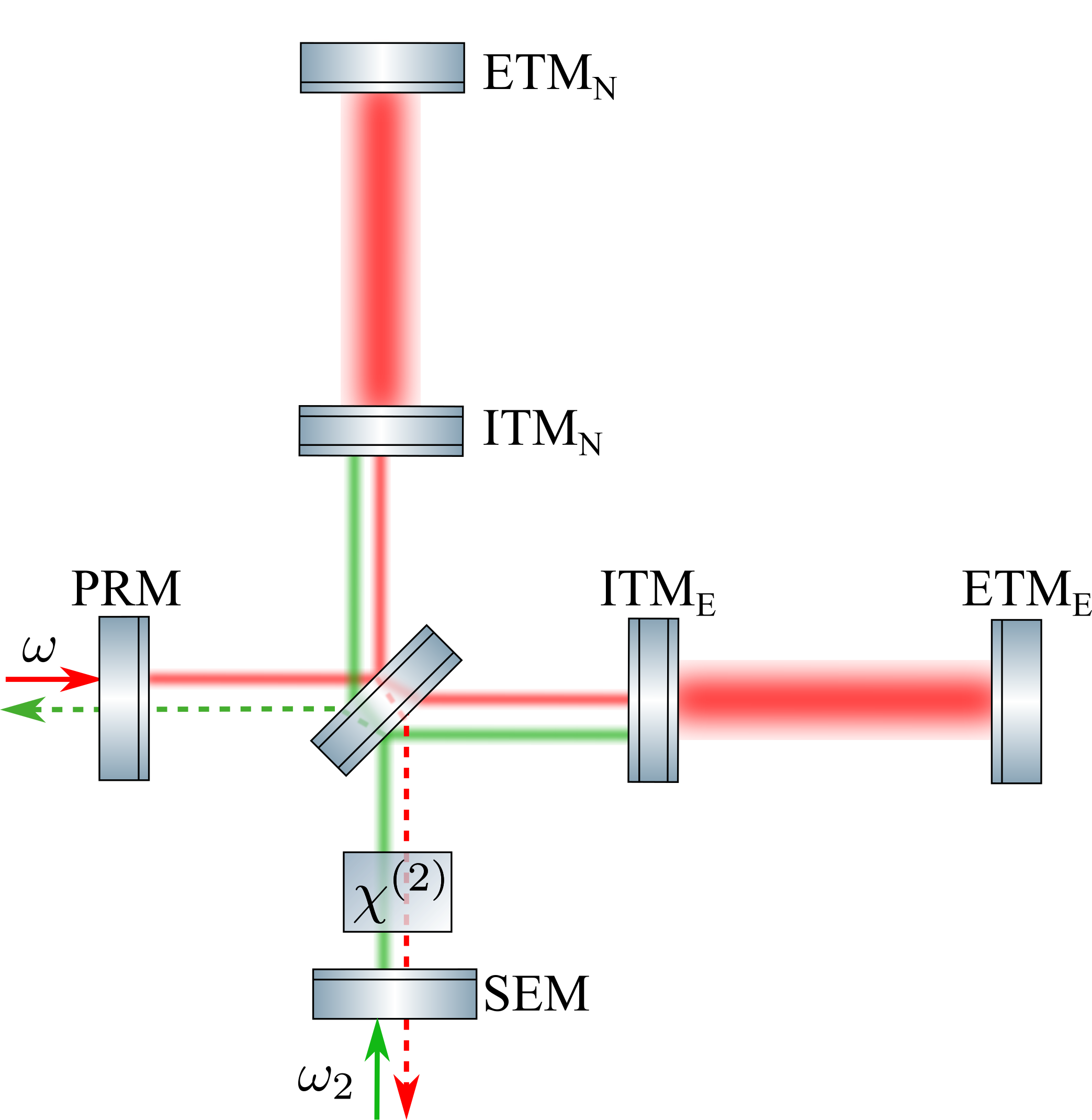
In this work we extend the consideration in Somiya et al. (2016) and analyse the more general situation, in which not only the parametric gain is varied but also the angle of the amplified quadrature amplitude. The parametric gain relates to the intensity of the second-harmonic pump field, whereas the angle relates to its phase. In particular the last parameter can be quickly changed providing a new degree of freedom for realizing dynamical detuning of the optical spring properties. We consider the internal quantum noise squeezing that is accompanied with the optical-parametric amplification together with the one from the optomechanical parametric amplification and derive spectral densities. Furthermore, we propose utilising the second-harmonic pump field to implement a ‘local readout’ of the motion of the arm cavity input test masses (ITMs) Rehbein et al. (2007), see Fig. 1. The local readout mitigates the unwanted effect of the optical spring, which is the rigid connection of the ITMs with their respective end test mass (ETM) at frequencies below the optical spring and a corresponding sensitivity loss at these frequencies.
The optomechanical system – The effects on the light field of both processes, the optical and the optomechanical parametric amplification, can be described in similar ways. Both result in a consecutive rotation of quadratures (determined by the phase of the pump for optical amplification and by the detuning of the SE cavity for the optomechanical one), squeezing (optical and ponderomotive correspondingly) and rotation again Harms et al. (2003); Danilishin and Khalili (2012). Both types of parametric amplification should thus influence the optical spring also in similar ways. In this section we derive explicitly the optical spring in the case of additional optical-parametric amplification inside the SR/SE cavity and show the effect of the squeeze angle.
We consider the dark port operation, at which all input light is retro-reflected from the interferometer. In this situation, the interferometer output field at the dark port contains the full information about the differential motion of the mirrors, and the output field at the bright port carries the full information about the common motion Caves (1981).
Let us first focus on the main interferometer that includes the arm cavities and is operated at optical frequency . This interferometer includes the far mirrors (ETMs) whose differential distance from the rest of the interferometer is directly excited by the gravitational wave. (Depending on the polarisation and direction of propagation of the gravitational wave, also their common distance is changed, however, its measurement is not targeted by a Michelson interferometer.)
With this in mind, we use an effective picture, where the interferometer is split into two separate cavity systems, coupled only via the displacement of the test mass mirrors Buonanno and Chen (2003).
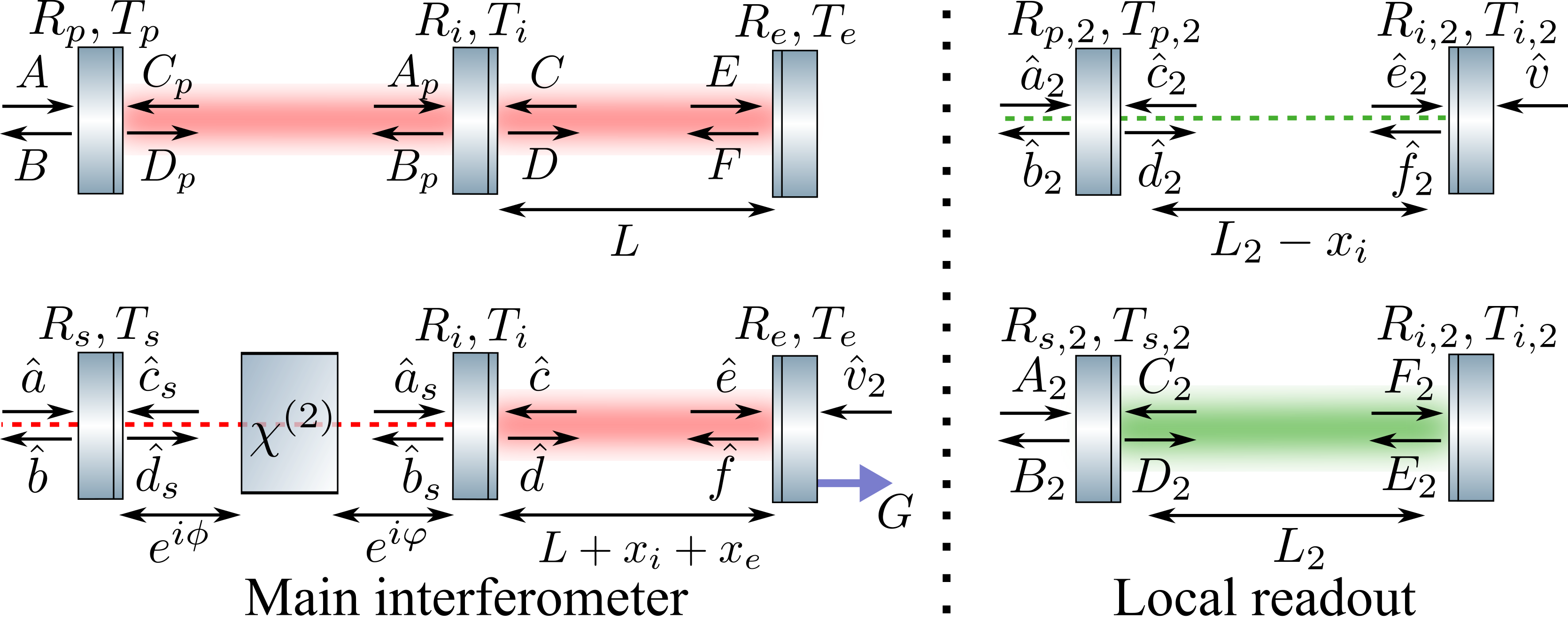
The first cavity system (Fig. 2, top left) corresponds to the common mode, whose modulation as well as its uncertainty are irrelevant for the signal-to-noise-ratio of a gravitational-wave signal in the differential mode. It is thus fully described by the classical carrier fields at frequency . The second one corresponds to the differential mode at and requires a quantised description (Fig. 2, bottom left). The other two systems in Fig. 2 (right) describe the short Michelson interferometer in Fig. 1 that uses light at for pumping the optical-parametric process and for measuring the differential motion of the ITMs. This part of the interferometer is considered in the section local readout further down.
The first mirrors of the main interferometer cavities (Fig. 2, left) are the power recycling (PRM) and signal extraction (SEM) correspondingly, and the middle (input, i) and the end (e) mirrors are combinations of ITM and ETM. Then the differential motion of four mirrors can be defined as the motion of input and end mirrors in the effective cavity picture:
| (1) |
Relative to the beam splitter only the far mirrors are accelerated due to the gravitational wave force , as the input mirrors are so close to the beam splitter that the effect can be neglected. On top, all mirrors are accelerated by the light’s radiation pressure force , which is proportional to the power of the light shining on the mirror and which we call back-action.
| (2) | ||||
| (3) |
where are mechanical susceptibilities of the input and end mirrors, that we assume here to be identical quasi-free masses of mass . The input mirror is driven by two different optical forces, due to the additional back-action from the second harmonic pump field.
The optical spring – When the cavity is detuned from resonance, the back-action force has a position-dependent dynamical part, causing the optical spring effect. We thus split the force into two contributions – the fluctuating part due to the quantum uncertainty of the light’s amplitude quadrature, and the optical spring force , where is the optical spring constant, also called optical rigidity .
We calculate the optical rigidity in the single-mode approximation, where the back-action on the input and end mirrors are identical, yielding
| (4) |
The single-mode approximation Danilishin and Khalili (2012) further involves (i) the sideband frequency and the arm cavity detuning being much smaller than the cavity free spectral range , with being the arm cavity length, and the speed of light, and (ii) the transmissivity of mirrors being small, so that we can make a Taylor expansion . The single-mode approximation enables us to introduce an effective linewidth and the detuning of the SE cavity as well as the normalised optical parametric gain (per cavity round trip) in the following way
| (5) | ||||
| (6) | ||||
| (7) |
| (8) |
where is the linewidth of the arm cavity, and are additional phases accumulated by the light field inside the SE cavity due to the cavity detuning and is a squeeze factor on the single pass through the optical-parametric amplifier.
We find that the optical parametric gain influences the total detuning of the interferometer as well as the light power associated with the optical spring
| (9) | ||||
| (10) |
where with the arm cavity detuning. is the phase of the optical-parametric amplification (the squeeze angle), and the normalised optical power with the power circulating in the arm cavities.
Given these definitions the optical rigidity is found to be
| (11) |
The optical spring, enhanced by the optical-parametric amplifier, has several important properties.
First, the maximal enhancement of the optical spring due to the internal squeezing is achieved if (for ) yielding . In this case, for instance, 3 dB of intra-cavity squeezing modifies the optical spring in the same way as doubling the optical power.
Second, we note that the internal squeezing changes the dynamics and stability of the system. The characteristic equation for the optomechanical motion is
| (12) |
The resonances can be found in the perturbative way by expanding the roots of Eq. (12) in powers of . Then zeroth order of expansion gives two positive roots:
| (13) |
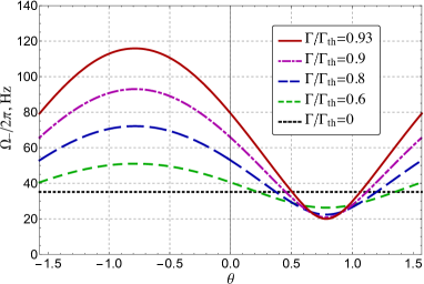
where corresponds to the shifted mechanical resonance, and to the optical resonance. In the absence of optomechanical coupling, , mechanical resonance is at zero, which corresponds to our assumption of having quasi-free masses, and . With increased effective power the mechanical resonance shifts to higher frequencies, and the optical one gets reduced, until, within the approximation used, these resonances become equal at the critical power F.Ya.Khalili (2001). Note that the absence of optomechanical coupling () can be due to zero power () or if the condition holds. Generally, the effective power can be changed by tuning the squeeze angle, without affecting neither light power nor squeeze factor, see Fig. 3.
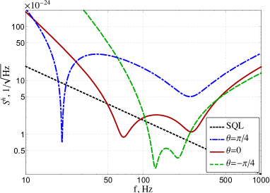
We propose thus to use this feature for dynamical tuning of the interferometer response to the GW signal. This way the mechanical resonance is changing adaptively to match the chirp GW signal, see Fig. 4. Tuning of the squeeze angle can be done in a straightforward way by tuning the phase of the second harmonic pump, e.g. by transmission through a fast electro-optical modulator. We note that the tuning speed is ultimately limited by the decay rate of the pump light’s cavity.
Third, using Routh-Hurwitz’ criterion Gradshteyn and Ryzhik (2007) one can show, that the system is always unstable, in the same way the optical spring without internal squeezing is Buonanno and Chen (2001, 2002, 2003). The mechanical system can be stabilised via active feedback Buonanno and Chen (2002). The optical-parametric process leads to an additional stability condition that has to be satisfied: , which is a threshold for optical-parametric instability.
Local readout –
The optical spring can be efficiently combined with the local readout Rehbein et al. (2007).
The idea of the local readout is based on that of the optical bar, proposed by Braginsky and co-authors.
At frequencies below the optomechanical resonance, the ITMs and ETMs are connected in a rigid way via dynamical backaction.
For this reason, at these low frequencies, the motion of the ETMs due to a gravitational wave causes an identical motion of the ITMs, which reduces the sensitivity at these frequencies.
The idea behind the local readout is to measure the motion of the ITMs locally and to use this information in the data processing. This way the sensitivity can be greatly improved at low frequencies.
Here we propose to use the second harmonic pump of the OPA to sense the local motion of the ITM.
In this case the dark port of a second small Michelson interferometer, formed by ITMs, coincide with the bright port of the main interferometer, see Fig. 1 and 2.
Both outputs have to be measured with balanced homodyne detectors with an optimal homodyne angle, and then combined in an optimal way.
For the local readout it is important to take the motion of the central beamsplitter into account, as the arm length of the small interferometer is rather short and arm cavities are not used.
Using the second harmonic pump instead of a nearby wavelength Rehbein et al. (2007) most likely eases the fabrication of the optical components that are part of both interferometers. The large wavelength separation allows to manufacture a highly reflective optical coating on the ITMs for the local readout beam, while keeping a moderate transmissivity for the main beam to allow for overcoupling of the input light.
The detection of the two beams can be done independently in efficient way, by separating the beams with dichroic beam splitters, which avoids using polarisation optics or filter cavities, as proposed in Rehbein et al. (2007).
Summary and outlook –
In this work, we analyse the optical spring that is created by the ‘conventional’ optomechanical parametric amplification inside a detuned cavity in combination with intra-cavity optical parametric amplification (OPA). Modifying the spectral density of the conventional optical-spring GW detector requires modifying the light power in the interferometer arms and/or changing the length of the signal recycling/signal extraction cavity. We find that the same modification is achieved for the OPA-enhanced optical spring by changing the power of the OPA pump light and/or by changing the phase of the pump light.
We conjecture that the latter parameters can be changed during an observational run of the GW detector more easily.
We also conjecture that in practice tuning and controlling these parameters should be possible with higher bandwidth, which is, however, ultimately limited by the pump light’s cavity decay rate.
Our analysis includes the effect of optical-parametric quantum noise squeezing inside the SR/SE cavity, which is also called internal squeezing Korobko et al. (2017). It is qualitatively different from external squeezing Caves (1981); Schnabel et al. (2010), which has been exploited in the GW detector GEO 600 since 2010 Abadie et al. (2011). Our analysis is in principle extendable to external squeezing, which was investigated in detail for the conventional optical spring in Harms et al. (2003).
We propose exploiting the second-harmonic pump field of the OPA for a local readout to increase the sensitivity at low frequencies.
The exploitation of the pump field as the second carrier field might also be interesting for other schemes such as the double optical spring Rehbein et al. (2008) or multi-carrier configurations Khalili et al. (2011); Voronchev et al. (2012); Korobko et al. (2015).
Our work extends both aspects of the optical bar, the optical spring as well as the local readout, towards gravitational-wave detectors with intra-cavity parametric amplification, and shows that such an approach allows versatile engineering of GW detector sensitivities.
Acknowledgments – The work of MK and RS was supported by the Deutsche Forschungsgemeinschaft (DFG) (SCHN 757/6-1). The work of FK was supported by LIGO NSF Grant PHY-1305863 and by Russian Foundation for Basic Research Grants 16-52-10069 and 16-52-12031.
Appendix A Appendix A: Input-output relations
It is helpful to consider the input-output relations of our opto-mechanical system in the ‘two-photon formalism’ Caves and Schumaker (1985); Schumaker and Caves (1985), where the amplitude and phase quadrature amplitudes and of the modulation field at frequency are linked to the optical fields via
| (14) | |||
| (15) |
Based on these quadrature amplitudes we define the vector .
The signal recycling cavity rotates the quadratures due to it’s detuning and squeezes and rotates additionally due to intra-cavity optical-parametric amplification. The phase shift due to the cavity length can be neglected since the cavity length is much shorter than the wavelengths of the sideband modulations considered here. The effect of the signal recycling cavity can be described as a set of rotations and squeezing operations:
| (16) | ||||
| (17) | ||||
| (18) | ||||
| (19) |
where we denote the amplitude reflectivity and transmissivity of the signal recycling and input mirrors by and the phase delay due to the cavity detuning before and after the crystal by , see Fig. 2. We now introduce the squeeze angle and the rotation matrix
| (20) |
| (21) |
and squeezing matrix
| (22) |
with being the single-pass squeeze factor.
For the arm cavity the corresponding set of equations reads
| (23) | ||||
| (24) | ||||
| (25) | ||||
| (26) | ||||
| (27) |
where is the wave vector of the main field, is the arm cavity detuning and is the propagation time with being the length of the arm cavity, and the speed of light. The field corresponds to the classical amplitude of the field impinging on the end mirror. This set of equations can be resolved for the outgoing field and intra-cavity fields .
We find the solution to these equations, first for the complex transmissivity and reflectivity of the signal recycling cavity
| (28) | |||
| (29) | |||
| (30) | |||
| (31) |
where we defined
| (32) | |||
| (33) | |||
| (34) |
That provides the solution for the signal extraction cavity
| (35) | |||
| (36) |
where
| (37) | |||
| (38) | |||
| (39) | |||
| (40) |
Now we can derive the fields for the arm cavity yielding
| (41) | |||
| (42) |
where
| (43) | ||||
| (44) |
Finally, we find the outgoing field to be
| (45) | ||||
| (46) | ||||
| (47) | ||||
| (48) |
Appendix B Appendix B: Radiation pressure
The radiation pressure force acting on the mirrors has three contributions. First, there is a constant force due to the classical high-power optical field. It induces a constant shift of the mirror, which can be compensated with classical feedback. Second, there is a dynamical classical part, which is amplified by opto-mechanical parametric amplification and which belongs to the optical spring, and third a fluctuating force due to the uncertainty in the amplitude quadrature of the light. The latter corresponds to the quantum back-action force of the carrier light and can be written for the input and end mirrors as
| (49) | |||
| (50) |
In the single-mode approximation, these two forces become equal and read
| (51) |
where
| (52) | |||
| (53) |
Ignoring the effect of the second-harmonic beam, we get for the differential motion
| (54) |
which allows us to introduce an effective susceptibility:
| (55) |
such that .
Appendix C Appendix C: Detection
The balanced homodyne detection on the output at homodyne angle provides the values
| (56) |
which we renormalise to the differential mirror displacement
| (57) |
From this we get the spectral density for this output
| (58) |
where
| (59) | |||
| (60) | |||
| (61) |
Finally we normalise the spectral density to the gravitational-wave strain yielding
| (62) |
References
- Braginsky and Minakova (1964) V.B. Braginsky and I.I. Minakova, “Influence of the small displacement measurements on the dynamical properties of mechanical oscillating systems,” Moscow Univ. Phys. Bull. 1, 83–85 (1964).
- Braginsky and Manukin (1967) V B Braginsky and A B Manukin, “Ponderomotive Effects of electromagnetic radiation,” Soviet Physics JETP 25, 653–655 (1967).
- Braginsky et al. (1997) V B Braginsky, M L Gorodetsky, and F Ya. Khalili, “Optical bars in gravitational wave antennas,” Physics Letters A 232, 340 (1997).
- Khalili (2002) F.Ya. Khalili, “The “optical lever” intracavity readout scheme for gravitational-wave antennae,” Physics Letters A 298, 308–314 (2002).
- S.L.Danilishin, F.Ya.Khalili (2006) S.L.Danilishin, F.Ya.Khalili, “Practical design of the optical lever intracavity topology of gravitational-wave detectors,” Physical Review D 73, 22002 (2006).
- Buonanno and Chen (2002) Alessandra Buonanno and Yanbei Chen, “Laser-interferometer gravitational-wave optical-spring detectors,” Classical and Quantum Gravity 19, 1569–1574 (2002).
- Meers (1988) Brian J Meers, “Recycling in laser-interferometric gravitational-wave detectors,” Physical Review D 38, 2317 (1988).
- Heinzel et al. (1998) G Heinzel, K A Strain, J Mizuno, K D Skeldon, and B Willke, “Experimental Demonstration of a Suspended Dual Recycling Interferometer for Gravitational Wave Detection,” Physical Review Letters 81, 5493 (1998).
- Mizuno et al. (1993) J Mizuno, K A Strain, P G Nelson, J M Chen, R Schilling, A Rüdiger, W Winkler, and K Danzmann, “Resonant sideband extraction: a new configuration for interferometric gravitational wave detectors,” Physics Letters A 175, 273–276 (1993).
- Heinzel et al. (1996) G Heinzel, J Mizuno, R Schilling, W Winkler, A Rüdiger, and K Danzmann, “An experimental demonstration of resonant sideband extraction for laser-interferometric gravitational wave detectors,” Physics Letters A 217, 305–314 (1996).
- Schliesser et al. (2006) A Schliesser, P Del’Haye, N Nooshi, K Vahala, and T Kippenberg, “Radiation Pressure Cooling of a Micromechanical Oscillator Using Dynamical Backaction,” Physical Review Letters 97, 243905 (2006).
- Aspelmeyer et al. (2014) Markus Aspelmeyer, Tobias J Kippenberg, and Florian Marquardt, “Cavity optomechanics,” Reviews of Modern Physics 86, 1391–1452 (2014).
- Metzger and Karrai (2004) Constanze Höhberger Metzger and Khaled Karrai, “Cavity cooling of a microlever.” Nature 432, 1002–1005 (2004).
- Meers et al. (1993) Brian J Meers, Andrzej Krolak, and J Alberto Lobo, “Dynamically tuned interferometers for the observation of gravitational waves from coalescing compact binaries,” Physical Review D 47, 2184–2197 (1993).
- Simakov (2014) D A Simakov, “Time-domain analysis of a dynamically tuned signal recycled interferometer for the detection of chirp gravitational waves from coalescing compact binaries,” Physical Review D 90, 102003 (2014).
- Sheard et al. (2004) Benjamin S Sheard, Malcolm B Gray, Conor M Mow-Lowry, David E McClelland, and Stanley E Whitcomb, “Observation and characterization of an optical spring,” Physical Review A 69, 51801 (2004).
- Miyakawa et al. (2006) Osamu Miyakawa, Robert Ward, Rana Adhikari, Matthew Evans, Benjamin Abbott, Rolf Bork, Daniel Busby, Jay Heefner, Alexander Ivanov, Michael Smith, Robert Taylor, Stephen Vass, Alan Weinstein, Monica Varvella, Seiji Kawamura, Fumiko Kawazoe, Shihori Sakata, and Conor Mow-Lowry, “Measurement of optical response of a detuned resonant sideband extraction gravitational wave detector,” Physical Review D 74, 022001 (2006).
- Corbitt et al. (2006) Thomas Corbitt, David Ottaway, Edith Innerhofer, Jason Pelc, and Nergis Mavalvala, “Measurement of radiation-pressure-induced optomechanical dynamics in a suspended Fabry-Perot cavity,” Physical Review A 74, 21802 (2006).
- Corbitt et al. (2007a) Thomas Corbitt, Yanbei Chen, Edith Innerhofer, Helge Müller-Ebhardt, David Ottaway, Henning Rehbein, Daniel Sigg, Stanley Whitcomb, Christopher Wipf, and Nergis Mavalvala, “An All-Optical Trap for a Gram-Scale Mirror,” Phys. Rev. Lett. 98, 150802 (2007a).
- Corbitt et al. (2007b) Thomas Corbitt, Christopher Wipf, Timothy Bodiya, David Ottaway, Daniel Sigg, Nicolas Smith, Stanley Whitcomb, and Nergis Mavalvala, “Optical Dilution and Feedback Cooling of a Gram-Scale Oscillator to 6.9 mK,” Physical Review Letters 99, 160801 (2007b).
- Hossein-Zadeh and Vahala (2007) Mani Hossein-Zadeh and Kerry J Vahala, “Observation of optical spring effect in a microtoroidal optomechanical resonator,” Optics Letters 32, 1611 (2007).
- Kelley et al. (2015) David Kelley, James Lough, Fabian Mangaña-Sandoval, Antonio Perreca, and Stefan W. Ballmer, “Observation of photothermal feedback in a stable dual-carrier optical spring,” Physical Review D 92, 062003 (2015).
- Sawadsky et al. (2015) Andreas Sawadsky, Henning Kaufer, Ramon Moghadas Nia, Sergey P Tarabrin, Farid Ya. Khalili, Klemens Hammerer, and Roman Schnabel, “Observation of Generalized Optomechanical Coupling and Cooling on Cavity Resonance,” Physical Review Letters 114, 43601 (2015).
- Edgar et al. (2016) M P Edgar, J Macarthur, B W Barr, S Hild, S Huttner, B Sorazu, and K A Strain, “Demonstration of an optical spring in the 100 g mirror regime,” Classical and Quantum Gravity 33, 075007 (2016).
- Singh et al. (2016) Robinjeet Singh, Garrett D. Cole, Jonathan Cripe, and Thomas Corbitt, “Stable Optical Trap from a Single Optical Field Utilizing Birefringence,” Physical Review Letters 117, 213604 (2016).
- Gordon et al. (2017) N A Gordon, B W Barr, A Bell, C Graef, S Hild, S H Huttner, S S Leavey, J Macarthur, B Sorazu, J Wright, and K A Strain, “Experimental demonstration of coupled optical springs,” Classical and Quantum Gravity 34, 035020 (2017).
- Affeldt et al. (2014) C Affeldt, K Danzmann, K L Dooley, H Grote, M Hewitson, S Hild, J Hough, J Leong, H Lück, M Prijatelj, S Rowan, A Rüdiger, R Schilling, R Schnabel, E Schreiber, B Sorazu, K a Strain, H Vahlbruch, B Willke, W Winkler, and H Wittel, “Advanced techniques in GEO 600,” Classical and Quantum Gravity 31, 224002 (2014).
- Aasi et al. (2015) J Aasi et al., “Advanced LIGO,” Classical and Quantum Gravity 32, 074001 (2015).
- Acernese et al. (2015) F Acernese et al., “Advanced Virgo: a second-generation interferometric gravitational wave detector,” Classical and Quantum Gravity 32, 024001 (2015).
- Somiya (2012) Kentaro Somiya, “Detector configuration of KAGRA–the Japanese cryogenic gravitational-wave detector,” Classical and Quantum Gravity 29, 124007 (2012).
- Somiya et al. (2016) K Somiya, Y Kataoka, J Kato, N Saito, and K Yano, “Parametric signal amplification to create a stiff optical bar,” Physics Letters A 380, 521–524 (2016).
- Rehbein et al. (2007) Henning Rehbein, Helge Müller-Ebhardt, Kentaro Somiya, Chao Li, Roman Schnabel, Karsten Danzmann, and Yanbei Chen, “Local readout enhancement for detuned signal-recycling interferometers,” Physical Review D 76, 62002 (2007).
- Harms et al. (2003) Jan Harms, Yanbei Chen, Simon Chelkowski, Alexander Franzen, Henning Vahlbruch, Karsten Danzmann, and Roman Schnabel, “Squeezed-input, optical-spring, signal-recycled gravitational-wave detectors,” Physical Review D 68, 42001 (2003).
- Danilishin and Khalili (2012) Stefan L Danilishin and Farid Ya Khalili, “Quantum Measurement Theory in Gravitational-Wave Detectors,” Living Reviews in Relativity 15, 1–147 (2012), arXiv:1203.1706 .
- Caves (1981) Carlton M. Caves, “Quantum-mechanical noise in an interferometer,” Physical Review D 23, 1693 (1981).
- Buonanno and Chen (2003) Alessandra Buonanno and Yanbei Chen, “Scaling law in signal recycled laser interferometer gravitational-wave detectors,” Physical Review D 67, 62002 (2003).
- F.Ya.Khalili (2001) F.Ya.Khalili, “Frequency-dependent rigidity in large-scale interferometric gravitational-wave detectors,” Physics Letters A 288, 251–256 (2001).
- Gradshteyn and Ryzhik (2007) I S Gradshteyn and I M Ryzhik, Table of integrals, series, and products, seventh ed. (Elsevier/Academic Press, Amsterdam, 2007) p. 1171.
- Buonanno and Chen (2001) Alessandra Buonanno and Yanbei Chen, “Optical noise correlations and beating the standard quantum limit in advanced gravitational-wave detectors,” Classical and Quantum Gravity 18, L95—-L101 (2001), arXiv:0102012 [gr-qc] .
- Korobko et al. (2017) M. Korobko, L. Kleybolte, S. Ast, H. Miao, Y. Chen, and R. Schnabel, “Beating the standard sensitivity-bandwidth limit of cavity-enhanced interferometers with internal squeezed-light generation,” Phys. Rev. Lett. 118, 143601 (2017).
- Schnabel et al. (2010) Roman Schnabel, Nergis Mavalvala, David E McClelland, and Ping Koy Lam, “Quantum metrology for gravitational wave astronomy.” Nature Communications 1, 121 (2010).
- Abadie et al. (2011) J. Abadie et al., “A gravitational wave observatory operating beyond the quantum shot-noise limit,” Nature Physics 7, 962–965 (2011).
- Rehbein et al. (2008) Henning Rehbein, Helge Mueller-Ebhardt, Kentaro Somiya, Stefan L. Danilishin, Roman Schnabel, K. Danzmann, and Yanbei Chen, “Double optical spring enhancement for gravitational wave detectors,” Physical Review D , 1–11 (2008).
- Khalili et al. (2011) Farid Khalili, Stefan Danilishin, Helge Müller-Ebhardt, Haixing Miao, Yanbei Chen, and Chunnong Zhao, “Negative optical inertia for enhancing the sensitivity of future gravitational-wave detectors,” Physical Review D 83, 62003 (2011).
- Voronchev et al. (2012) N. V. Voronchev, S. L. Danilishin, and F. Ya. Khalili, “Negative optical inertia in optomechanical systems,” Optics and Spectroscopy 112, 377–385 (2012).
- Korobko et al. (2015) Mikhail Korobko, Nikita Voronchev, Haixing Miao, and Farid Ya. Khalili, “Paired carriers as a way to reduce quantum noise of multicarrier gravitational-wave detectors,” Physical Review D 91, 042004 (2015).
- Caves and Schumaker (1985) Carlton M. Caves and Bonny L. Schumaker, “New formalism for two-photon quantum optics. I. Quadrature phases and squeezed states,” Physical Review A 31, 3068–3092 (1985).
- Schumaker and Caves (1985) Bonny L. Schumaker and Carlton M. Caves, “New formalism for two-photon quantum optics. II. Mathematical foundation and compact notation,” Physical Review A 31, 3093–3111 (1985).