Coupling of evanescent waves into propagation channels within two-dimensional random waveguides
Abstract
The transformation from evanescent waves to propagation waves is the key mechanism for the realization of some super-resolution imaging methods. By using the recursive Green function and scattering-matrix theory, we investigated in details on the transport of evanescent waves through a random medium and analyzed quantitatively the coupling of evanescent channels to propagation channels. By numerical calculations, we found that the transmission for the incident evanescent channel is determined by both the eigenvalues of the scattering matrix and the coupling strength to the corresponding propagation channels in random medium, and the disorder strength of the random medium influences both of them.
I Introduction
In the past two decades, many new principles and schemes to realize an imaging beyond the diffraction limit () have been proposedzhuang2010 ; betzig1992 ; pendry2000 ; liu2007 ; liu2007nl ; Lerosey2007 ; Putten2011 ; Rotter2017 , which generally can be divided into two categories, i.e. super-solution fluorescence microscopy techniques and noninvasive and label-free super-solution microscopy techniques, e.g. atomic force microscopy (AFM), the Scanning Near-Field Optical Microscopy (SNOM) and etc. The latter relies on quantum or purely optical technologies. As for the optical super-resolution microscopy techniques such as SNOM, from the view point of optics, to realize the so-called super-resolved imaging, it is required to deliver and recover the subwavelength information from the object onto the image.
The subwavelength information of an object is carried by evanescent waves, which decay exponentially in space and vanish in the order of wavelength , leading to the diffraction limit in conventional optics. To realize the far-field super-resolution imaging, one approach is to recover the subwavelength information carried by evanescent waves by placing a subwavelength-sized aperture or sharp stylus in the near-field region () of the object and converting the evanescent waves into propagating waves, which can be detected in the far-field microscope. The resolution limit of microscopy technologies based on such near-field imaging mechanismbetzig1992 ; Zenhausern1995 , e.g. SNOMASH1972 ; Hecht2000 , is determined by the size of the aperture or sharp stylus and reaches the resolution of tens of nanometers () recentlyTaminiau2007 .
In addition to the near-field optical microscopy techniques, Pendry et. al. proposed the concept of superlens, which consists a thin slab composed of the material with negative permittivity, permeability or bothpendry2000 ; smith2005 ; fang2005 . Superlens transmits evanescent waves by the excitation of surface plasmons and allows the recovery of evanescent waves at the imagefang2005 . Since no transformation from evanescent to propagating waves take place, superlens can only produce a near-field super-resolved imaging. To convert evanescent waves to propagating waves and realize far-field super-resolved imaging, the concept of hyperlens is proposedjacob2006 ; liu2007 , which is constructed by cylindrical layered metamaterials with a hyperbolic dispersion, allowing the propagation of waves with very large spatial frequency. i.e. evanescent waves in vacuum, which finally recover the subwavelength information at the far-field image.
Recently an approach for subwavelength imaging based on the transformation of evanescent waves to propagating waves and time-reversal principle was proposedLerosey2007 , and the optical configuration composes a microstructured random media in the near-field region of the object to convert evanescent waves to propagating waves, and a far-field () time-reversal mirror (TRM) to build the time-reversed wave field, which will finally form a focus at the target. The resolution of such a method for microwaves reaches a value as small as one-thirtieth of a wavelengthLerosey2007 . Obviously, the transformation mechanism of evanescent waves to propagating waves plays a crucial role in the explanation of such super-resolution imaging.
However, although such a super-resolution imaging method has been widely used in telecommunication, and much effort has been devoted on the investigation and control of propagation of light through a random medium to realize the subwavelength imagingVellekoop2007 ; Popoff2010 ; Putten2011 , the conversion of evanescent waves to propagation waves in the random medium is still lack of quantitative analysis.
In this work, we report a quantitative analysis on the coupling of incident evanescent waves to the propagation waves in the random medium by the numerical investigation on the light transport from a two-dimensional homogeneous waveguide through a two-dimensional random waveguide. The energy carried by the evanescent channel is coupled to and then delivered by the propagation channel in the random medium and then coupled to the outgoing channels. The disorder strength of the random medium will influence the energy distribution within the propagation channels and determine the corresponding channel transmission.
II Numerical Model and Methods
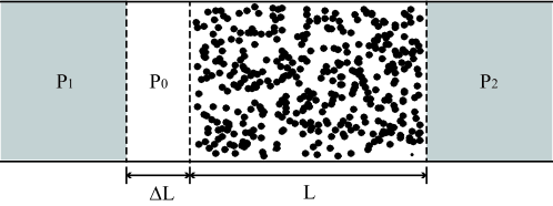
To simplify the problem, here we consider a simple model composed of a two-dimensional random waveguide (2DRW) attached by two 2D semi-infinite homogeneous waveguides, as shown in Fig. 1. The width of the 2DRW is , the left/right free waveguides with respective refractive indices of and are denoted by . For simplification, the imaginary parts of the dielectric constants are neglected. The width of the random scatterers is , and the distribution of the dielectric function of region is described by
| (1) |
where is distributed in a homogeneous random pattern in the region , in which is the disorder parameter. In order to generate an incident evanescent wave, in the region between and , a homogeneous waveguide with the size of is inserted, and denoted by . The refractive index of is .
The transverse boundaries of the 2DRW system are perfectly reflective, and a monochromatic and z-polarized light propagates along the x direction, which is governed by the Helmholtz equation,
| (2) |
where is the light wavevector in vaccum, and is the spatial distribution of dielectric functions for the 2DRW system.
Within the semi-infinite homogeneous waveguides , according to the waveguide theory, the propagation modes can be quantized into transverse modes, which are generally called as “channels”Beenakker1997 ; xu2017 . In the context of the scattering-matrix theoryBeenakker1997 ; Fisher1981 , the transport of light through a random-scattering region can be described by the scattering matrix , whose elements represents the complex field transmission amplitude from the incoming channel to the outgoing channle and can be calculated by the Fisher-Lee relationFisher1981 ,
| (3) |
where is the group velocity of the channel in the corresponding homogeneous waveguide, is the transverse wave function of the mode which has the form of standing waves due to the perfect reflections on both transverse boundaries. is the retarded Green function describing light propagation from the source point to the probe point , which can be calculated by the recursive Green function (RGF) methodMacKinnon1985 ; Baranger1991 ; xu2016 ; xu2017 .
If the left and right semi-infinite homogeneous waveguides possess an identical width and dielectric constant, the number of propagation modes they support are identical. The total transmission for an incident channel , i.e. , can be calculated by summation over the contribution from all the outgoing channels , as follows,
| (4) |
When the size of is zero, i.e. , since the two homogeneous waveguides in the left and right sides of the region support propagation modes with different number, i.e. and (, due to ), the dimension of the scattering matrix for light propagating through the region is . The singular-value decomposition of can be written as,
| (5) |
where the matrix is the matrix mapping the incident channels in the left waveguide to the eigen channels in the region, while the matrix is the matrix mapping the eigen channels in the region to the output channels in the right waveguide.
If , the diagonal matrix possesses singular values of the scattering matrix , and mello1988 , which are regarded as propagation channels in the waveguides. In fact, one can obtain eigenvalues by diagonalizing the Hermitian matrix , however, the values for the modes larger than are equal to zero, i.e. , which can be regarded as the evanescent channels in the region.
III Numerical Results
III.1 Wave transport within homogeneous waveguides
As we know, within homogeneous waveguide, the number of the propagating modes can be obtained as,
| (6) |
where is the refractive index of the waveguide, and is the width of the waveguide. For the homogeneous waveguides shown in Fig. 1, the numbers of the propagating modes are different since . Here, we denote the number of the propagating modes in homogeneous waveguides as , respectively.
When the refractive index of is larger than that of , i.e., waveguide will support more propagating modes than , i.e. , according to Eq. (6), which means that some higher-order propagating modes in will be totally reflected at the interface between and , and emerge as evanescent mdoes in , which will propagate within a short distance in the order of wavelength and then vanish.
For the channel in the homogeneous waveguide , the relation between and can be written as,
| (7) |
where is the refractive index in the region. According to the waveguide theory, the normal component of wavevector , and the propagating modes thus can be sorted by the propagation angles determined by .
For simplicity without loss of generality, here we choose the geometric parameters and materials properties of the waveguide model as , , , and . The widths of the respective waveguide regions are normalized by the light wavevector in vaccum . According to Eq. (6), the numbers of propagating modes within are and , respectively. The propagating modes are sorted by the incident angles . As mentioned above, there are three modes, i.e. modes No. 17-19, propagating within will be totally reflected at the interface between and , since can support only 16 propagating modes.
III.2 Propagating modes through the RS region
To investigate the influence on the propagation modes from the different levels of random scattering in the region, the width of the is set to be zero, i.e. , and then we changed the disorder parameter in the region. By using the RGF method described above, the averaging transmission for different incident channels , i.e. , is calculated for random system with different disorder parameter , as shown in Fig. 2.

It is clearly shown that, for the propagation modes propagating within this 2DRW, the value of decreases when the disorder parameter in the region increases, which is due to the scattering events occur in the region.
III.3 Evanescent modes through the RS region
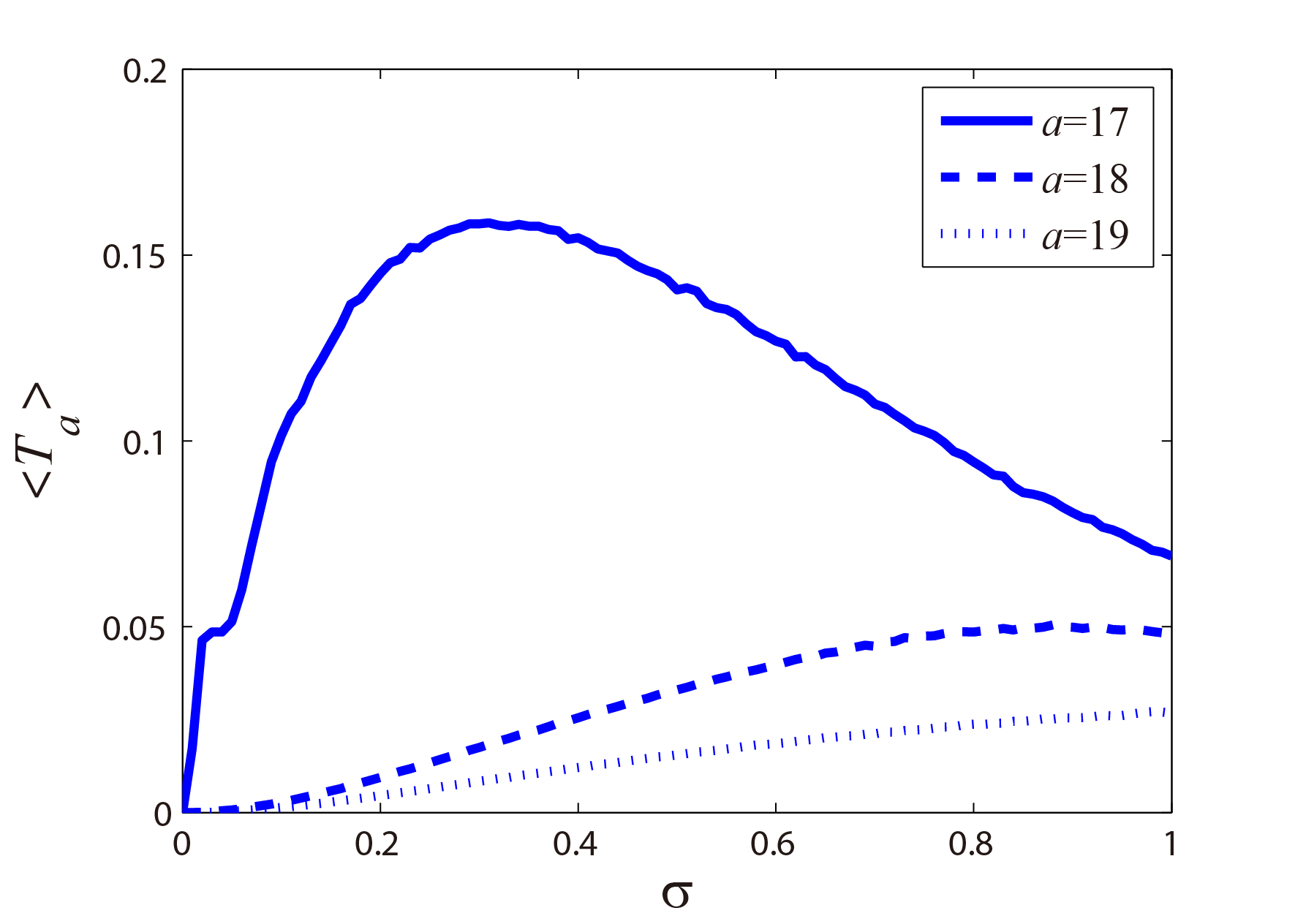
For comparison, the behaviors of averaging transmission for evanescent modes, i.e. modes No. 17-19, are shown in Fig 3. When the region is free from randomly distributed scatterers, i.e. , the values of averaging transmission for all evanescent modes are equal to zero, as shown in Fig. 3, which is due to the fact that propagation modes No. 17-19 in the waveguide are totally reflected at the interface between and (note that ) and the evanescent modes can propagate nontrivially within a short distance . However, when random scatterings indeed occur in the region, i.e. , the behaviors of for evanescent modes are quite different from those for propagation modes shown in Fig. 2. For evanescent modes No. 17-18, there are some peaks in the curves and No. 19 mode increases when the disorder parameter increases. Since the amplitude of is far from zero, it can come to the conclusion that the evanescent channels within the region also carry nontrivial energy.
In order to eliminate the influence from the interface scattering taking place at the interface between the and regions, in Fig. 4, we calculate the for the case with an increasing and a fixed disorder parameter . For modes No. 18 and 19, the values of decrease exponentially when the size of increases, which confirms that these two modes are evanescent within the region. The inclination of for mode 19 is much larger than that for the mode 18 is due to the fact that caused by .

However, the case for the incident mode 17 whose incident angle is close to the total-reflection angle, is quite different, the value of keeps nontrivial even when the size of , i.e. , shown as the inset in Fig. 4, probably due to the small mismatch between the incident mode 17 and the eigen-mode of the region.
III.4 Averaging transmission of the RS region
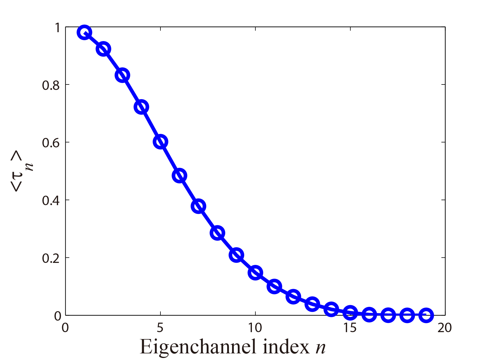
To further investigate the underlying mechanism of the nontrivial transmission for incident evanescent channels, we set the size of to zero, i.e. , and the disorder parameter is fixed to 0.5, to calculate the averaging eigen values of the scattering matrix for region. As mentioned above, since the number of propagation modes in is larger than that in , i.e. , the eigen values of the scattering matrix for the region possess nonzero values, and the eigen values for modes larger than are all equal to zero, i.e.
| (8) |
By using the RGF method, we calculate the averaging eigen values of the scattering matrix for the region, which are also the averaging transmission for different incident channels . The calculated results are shown in Fig. 5, which also validates the analystical expression for the eigen channels for the region, as described by Eq. (8).
IV Discussions
From the averaging eigen values of the scattering matrix for the region, as shown in Fig. 5, the evanescent channels of the region, i.e. eigenchannels No. 17-19 here, can neither propagate and nor carry nontrivial energy and thus behave like evanescent waves. Thus, the nontrivial transmission for the incident evanescent modes from can not be understood by the coupling of incident energy into the evanescent channels of the region.
According to the scattering matrix method, the coupling coefficient for the incident channel in waveguide into the eigenchannel in the region is the element of the mapping matrix in Eq. (5), i.e. , and the coupling strength can be defined as . It should be noted that, as shown in Fig. 5, the energy coupled into the evanescent channel of the region is equal to zero and contributes nothing to the total transmission. For the incident channel , the transmission can be written as,
| (9) |
According to Eq. (9), the total transmission for an incident channel , i.e. , is determined by the weighted summation over the contribution from different eigenchannels of the region, and the weighted factor is the coupling strength . Furthermore, no coupling between the eigenchannels of the region can be found. Therefore, the total transmission for an incident channel is determined by both the coupling strength and eigen values of the scattering matrix in region, which is the reason why the coupling into evanescent channels in the region contributes nothing to the total transmission.
By ensemble averaging the total transmission for an incident channel , the average coupling strength for channel can be defined as,
| (10) |
For comparison, a series of samples with different disorder parameters are investigated, and only the evanescent channels are considered, as shown in Figs 6-7. When the region is free from random scatterers, i.e. , and can be regarded as homogeneous waveguide with , the calculated averaging coupling strengths for the incident evanescent channels, i.e. (), have the value of one, as shown in Fig. 6, which means that these three evanescent channels in waveguide are perfectly coupled to the corresponding evanescent channels in the region. This is easy to understand by the fact that, under such a condition, regions of and are homogeneous waveguides with identical dielectric constant and width.
Since the eigen values for the evanescent channels in the region are all equal to zero () and carrying no energy, therefore, the corresponding transmissions are equal to zero, i.e. . In such situation, total reflections happen at the interface between the and regions for these evanescent channels.
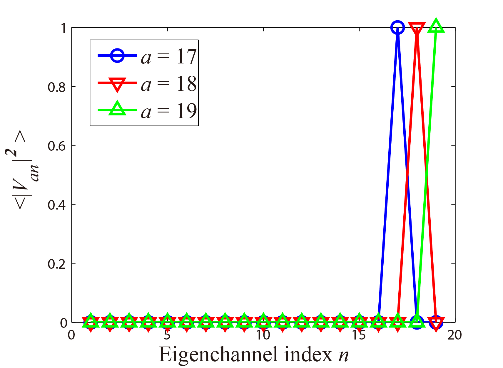
When random scatterings are introduced, i.e. , it has been shown in Figs. 3-4 that nontrivial transmitted energy emerge from the interface between the and for incident evanescent channels. The averaging coupling strength for evanescent channels are shown in Fig. 7.
For all the evanescent channels, it is shown in Fig. 7 that the maximum coupling strength is the coupling to the corresponding channel with the same index, i.e. , due to the small mismatch between the incident channel and the channel in the region with the same channel index.
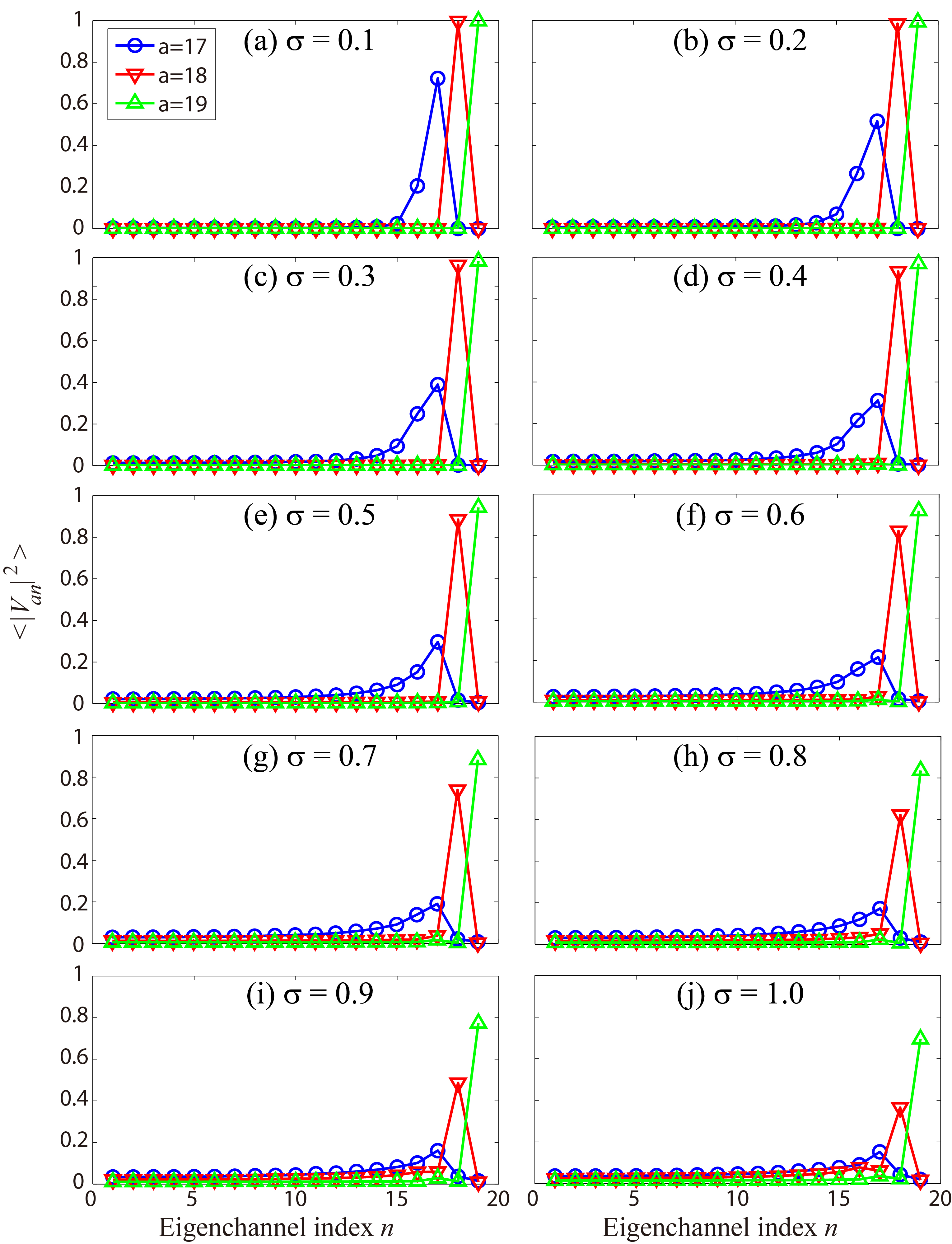
When the disorder parameter increases, the coupling from incident evanescent channels in waveguide to the propagation channels in the region become nontrivial. Here, taking the case of channel 17 as an example, the averaging coupling strength to propagation channel in region is close to 0.2 when , i.e. shown in Fig. 7(a), therefore the energy carried by the propagation channel will contribute nontrivially to the total transmission. While the value of is much larger than , the energy transported by channel 17 in the region is trivial since the channel in region is evanescent, therefore the nontrivial transmission for incident channel 17, i.e. as shown in Fig. 4, is contributed from the coupling of energy from the incident channel 17 in region to the propagation channel 16 in region. At the output interface between and regions, a reverse coupling process occurs.
When the disorder paramter increases further, more eigen channels of the region are roused and participate the process of carrying energy to the output interface, which subsequently increases the transmission for the incident channel , as shown in Fig. 3, since the value of the eigen channel of the region are larger when the channel index is smaller, as shown in Fig. 5. However, as shown in Fig 7, the overall values of the coupling strength for channel decrease when the disorder parameter increases, therefore, the total transmission for the incident channel will reach a peak value and then decrease, as shown in Fig. 3, since is determined by the weighting summation over the multiplication of coupling strength and eigenvalue of channels .
Similar analysis can be performed for the cases of other incident evanescent channels, i.e. here.
Therefore, by finely tuning the disorder strength of random scatterers in the region, it is possible to realize an optimized transmission of light with a large incident angle, which is an evanescent mode in the corresponding homogeneous waveguide. Moreover, the transmission for light with a large incident angle can be possibly optimized further by artificially coupling into the propagation channels of the region through the wavefront-shaping techniques, which is the underlying mechanism for the so-called scattering lensVellekoop2007 ; Putten2011 .
V Conclusion
In conclusion, we have used the RGF method and scattering-matrix method to investigate quantitatively in details the coupling of incident evanescent channels to the propagation channels in the random-scattering region. The energy carried by the incident evanescent channels, which were considered to be totally reflected at the interface, are coupled to the propagation channels in the random-scattering region, and then coupled to the output channels, which finally leads to the nontrivial energy transmission with a peak value for the incident evanescent channels. Our finding provides a clear and quantitative analysis on the far-field super-resolution imaging caused by evanescent-propagation transition mechanism, and will help to improve the far-field super-resolution imaging based on the wavefront-shaping technique.
Acknowledgement
This work is supported by the National Natural Science Foundation of China under Grants No. 11374063, and the National Basic Research Program of China (973 Program) under Grant No. 2013CBA01505. Work at Ames Laboratory is partially supported by the U.S.Department of Energy, Office of Basic Energy Science, Division of Materials Science and Engineering (Ames Laboratory is operated for the U.S. Department of Energy by Iowa State University under Contract No. DE-AC02-07CH11358). The European Research Council under ERC Advanced Grant No. 320081 (PHOTOMETA) supports work at FORTH.
Reference
References
- (1) Bo Huang, Hazen Babcock, and Xiaowei Zhuang. Breaking the diffraction barrier: Super-resolution imaging of cells. Cell, 143(7):1047 – 1058, 2010.
- (2) Eric Betzig and Jay K. Trautman. Near-field optics: Microscopy, spectroscopy, and surface modification beyond the diffraction limit. Science, 257(5067):189–195, 1992.
- (3) J. B. Pendry. Negative refraction makes a perfect lens. Phys. Rev. Lett., 85:3966–3969, Oct 2000.
- (4) Zhaowei Liu, Hyesog Lee, Yi Xiong, Cheng Sun, and Xiang Zhang. Far-field optical hyperlens magnifying sub-diffraction-limited objects. Science, 315(5819):1686–1686, 2007.
- (5) Zhaowei Liu, Stéphane Durant, Hyesog Lee, Yuri Pikus, Nicolas Fang, Yi Xiong, Cheng Sun, and Xiang Zhang. Far-field optical superlens. Nano Letters, 7(2):403–408, 2007. PMID: 17298007.
- (6) Geoffroy Lerosey, Julien de Rosny, Arnaud Tourin, and Mathias Fink. Focusing beyond the diffraction limit with far-field time reversal. Science, 315(5815):1120–1122, 2007.
- (7) E. G. van Putten, D. Akbulut, J. Bertolotti, W. L. Vos, A. Lagendijk, and A. P. Mosk. Scattering lens resolves sub-100 nm structures with visible light. Phys. Rev. Lett., 106:193905, May 2011.
- (8) Stefan Rotter and Sylvain Gigan. Light fields in complex media: Mesoscopic scattering meets wave control. Rev. Mod. Phys., 89:015005, Mar 2017.
- (9) F. Zenhausern, Y. Martin, and H. K. Wickramasinghe. Scanning interferometric apertureless microscopy: Optical imaging at 10 angstrom resolution. Science, 269(5227):1083–1085, 1995.
- (10) E A Ash and G Nicholls. Super-resolution Aperture Scanning Microscope. Nature, 237(5357):510–512, jun 1972.
- (11) Bert Hecht, Beate Sick, Urs P. Wild, Volker Deckert, Renato Zenobi, Olivier J. F. Martin, and Dieter W. Pohl. Scanning near-field optical microscopy with aperture probes: Fundamentals and applications. The Journal of Chemical Physics, 112(18):7761–7774, 2000.
- (12) Tim H. Taminiau, Robert J. Moerland, Frans B. Segerink, Laurens Kuipers, and Niek F. van Hulst. lambda/4 resonance of an optical monopole antenna probed by single molecule fluorescence. Nano Letters, 7(1):28–33, 2007. PMID: 17212435.
- (13) David R. Smith. How to build a superlens. Science, 308(5721):502–503, 2005.
- (14) Nicholas Fang, Hyesog Lee, Cheng Sun, and Xiang Zhang. Sub&150;diffraction-limited optical imaging with a silver superlens. Science, 308(5721):534–537, 2005.
- (15) Zubin Jacob, Leonid V. Alekseyev, and Evgenii Narimanov. Optical hyperlens: Far-field imaging beyond the diffraction limit. Opt. Express, 14(18):8247–8256, Sep 2006.
- (16) I. M. Vellekoop and A. P. Mosk. Focusing coherent light through opaque strongly scattering media. Opt. Lett., 32(16):2309–2311, Aug 2007.
- (17) Sebastien Popoff, Geoffroy Lerosey, Mathias Fink, Albert Claude Boccara, and Sylvain Gigan. Image transmission through an opaque material. Nat Commun, 1:81, September 2010.
- (18) C. W. J. Beenakker. Random-matrix theory of quantum transport. Rev. Mod. Phys., 69:731–808, Jul 1997.
- (19) Yuchen Xu, Hao Zhang, Yujun Lin, and Heyuan Zhu. Light transmission properties in inhomogeneously-disordered random media. Ann. Phys., pages 1600225–n/a, 2017. 1600225.
- (20) Daniel S. Fisher and Patrick A. Lee. Relation between conductivity and transmission matrix. Phys. Rev. B, 23:6851–6854, Jun 1981.
- (21) A. MacKinnon. The calculation of transport properties and density of states of disordered solids. Z. Phys. B, 59(4):385–390, 1985.
- (22) Harold U. Baranger, David P. DiVincenzo, Rodolfo A. Jalabert, and A. Douglas Stone. Classical and quantum ballistic-transport anomalies in microjunctions. Phys. Rev. B, 44:10637–10675, Nov 1991.
- (23) Yuchen Xu, Hao Zhang, Yujun Lin, and Heyuan Zhu. Light transport in quasi-one-dimensional disordered waveguides composed of locally two-dimensional random square lattices. J. Mod. Opt., 64:1215–1221, 2017.
- (24) PA Mello, P Pereyra, and N Kumar. Macroscopic approach to multichannel disordered conductors. Ann. Phys., 181(2):290–317, 1988.