Polarization entanglement purification of nonlocal microwave photons based on the cross-Kerr effect in circuit QED111Published in Phys. Rev. A 96, 052330 (2017).
Abstract
Microwave photons have become very important qubits in quantum communication as the first quantum satellite has been launched successfully. Therefore, it is a necessary and meaningful task for ensuring the high security and efficiency of microwave-based quantum communication in practice. Here, we present an original polarization entanglement purification protocol for nonlocal microwave photons based on the cross-Kerr effect in circuit quantum electrodynamics (QED). Our protocol can solve the problem that the purity of maximally entangled states used for constructing quantum channels will decrease due to decoherence from environment noise. This task is accomplished by means of the polarization parity-check quantum nondemolition (QND) detector, the bit-flipping operation, and the linear microwave elements. The QND detector is composed of several cross-Kerr effect systems which can be realized by coupling two superconducting transmission line resonators to a superconducting molecule with the -type level structure. We give the applicable experimental parameters of QND measurement system in circuit QED and analyze the fidelities. Our protocol has good applications in long-distance quantum communication assisted by microwave photons in the future, such as satellite quantum communication.
pacs:
03.67.Pp, 85.25.Dq, 42.50.Pq, 03.67.HkI Introduction
Quantum entanglement is an indispensable resource for quantum communication, such as quantum teleportation CHBennet1993 , quantum dense coding CHBennet1992 ; superdense , quantum key distribution AKEkert ; bbm92 ; lixhqkdpra , quantum secret sharing MHillery , and quantum secure direct communication longliupra ; FGDeng2003 ; QSDCWangC ; twostepexp . To accomplish the quantum communication efficiently, the two legitimate remote parties usually use the photon pairs in maximally entangled states to construct their communication channel. Due to the decoherence from the environment in practice, the maximally entangled state will become a partially entangled state or a mixed entangled one. This consequence inevitably reduces the efficiency of the whole communication process. Therefore, some interesting methods are proposed to improve the efficiency of quantum communication, such as the error-rejecting coding with decoherence-free subspaces DFS1 ; DFS2 ; DFS3 , entanglement concentration CHBennett1996 ; YBSheng2008 ; BCRen012302 ; Lixhpraecp ; HZhangPRA2017 , and entanglement purification EPP1 ; DDeutschPRL1996 ; JWPannature2001 ; Simon2002 ; JWPannature2003 ; YBShengPRA2008 ; EPP2 ; EPP3 ; EPP4 ; dengonestep ; EPP5 ; GYWangPRA2016 ; CWangECPPRA11 ; EPPadd1 ; EPPadd2 .
Entanglement purification is used to transfer a nonlocal mixed entangled state to a higher purity entangled state. It is a key technique in quantum repeaters for long-distance quantum communication to depress the harmful influence of noise. To date, some interesting entanglement purification protocols (EPPs) have been proposed EPP1 ; DDeutschPRL1996 ; JWPannature2001 ; Simon2002 ; JWPannature2003 ; YBShengPRA2008 ; EPP2 ; EPP3 ; EPP4 ; dengonestep ; EPP5 ; GYWangPRA2016 ; CWangECPPRA11 ; EPPadd1 ; EPPadd2 . For example, in 1996, Bennett et al. EPP1 proposed an original EPP for photon pairs in a Werner state RFWernerPRA1989 by using two controlled-NOT gates and single-photon measurements. In 2001, Pan et al. JWPannature2001 presented an EPP for a general mixed entangled state for an ideal entanglement source with simple linear optical elements. In 2002, Simon and Pan Simon2002 proposed an EPP for a nonideal spontaneous parametric down conversion (PDC) source assisted by using spatial entanglement. In 2003, Pan et al. JWPannature2003 demonstrated this EPP by using linear optical elements. In 2008, Sheng et al. YBShengPRA2008 proposed an efficient polarization EPP for a PDC source based on the cross-Kerr effect. In 2010, Sheng and Deng EPP2 introduced the original EPP for two-photon systems in a deterministic way. In 2014, Ren and Deng EPP5 proposed a two-step hyperentanglement purification protocol (hyper-EPP) for two-photon four-qubit systems in nonlocal polarization-spatial hyperentangled Bell states. In 2016, Wang, Liu, and Deng GYWangPRA2016 presented a universal method for hyper-EPP in the polarization degree of freedom and multiple-longitudinal-momentum degrees of freedom with SWAP gates.
Circuit quantum electrodynamics (QED), which couples the superconducting qubit to superconducting transmission line resonators (TLRs), provides a way to study the fundamental interaction between light and matter ABlais ; AWallraff . It holds a big advantage on good scalability for quantum information processing ABlais2 ; DiCarlo ; LongcircuitPRA ; Wangsuperconducting ; circuitTianlPRL ; 3q ; 3q1 ; RVijaynature ; Frederick1 . Many studies have focused on circuit QED AAHouck ; MHofheinz ; JMajer ; DISchuster ; BRJohnson ; HuaMPRA ; Narlaprx2016 . As a very important and interesting phenomenon, the cross-Kerr effect has been researched in circuit QED in recent years SRebic2009 ; SKumarPRB2010 ; YHu ; GKirchmair ; ICHoi ; ETHolland . For example, in 2009, Rebić et al. SRebic2009 proposed the giant Kerr nonlinearities at microwave frequencies in circuit QED. In 2011, Hu et al. YHu presented a theoretical scheme to generate the cross-Kerr effect between two TLRs. In 2013, Hoi et al. ICHoi observed the giant cross-Kerr effect for propagating microwaves experimentally induced by an artificial atom. In 2015, Holland et al. ETHolland demonstrated the single-photon resolved cross-Kerr effect between two microwave resonators in experiment. A microwave photon is a very important qubit for quantum communication because of its low loss and strong anti-interference during transmission. Due to the decoherence from environment, the maximally entangled microwave photon state may become a partially entangled pure state or a mixed one in the process of transmission and storage. To keep the high efficiency and fidelity of quantum communication, the legitimate parties in quantum communication should make an entanglement concentration or purification on the partially entangled microwave photon state or the mixed one, respectively. An original entanglement concentration protocol has been proposed for microwave photons HZhangPRA2017 . To date, there is no research on entanglement purification of the nonlocal entangled states of microwave-photon pairs. Therefore, the entanglement purification of microwave-photon states is an extremely important and necessary task for microwave-based quantum communication. The microwave photon qubit can be manipulated effectively Narlaprx2016 ; JMHao ; DRSolli1 . For example, Narla et al. Narlaprx2016 realized the basic microwave beam splitter which plays a very important role for microwave homodyne detection and used it to generate the robust concurrent remote entanglement between two superconducting qubits. The polarization can be manipulated by adjusting the material parameters JMHao ; DRSolli1 .
In this paper, we propose a physically feasible polarization EPP on the nonlocal entangled microwave photons in circuit QED. By using our EPP, the parties can effectively purify the mixed entangled states induced by the decoherence from environment noise in microwave-based quantum communication. This task is achieved with the polarization parity-check QND measurements on microwave-photon pairs, the bit-flipping operations, and the linear microwave elements. The parity-check quantum nondemolition (QND) detector is composed of two cross-Kerr systems for microwave photons and is a crucial part to implement the polarization entanglement purification. We give the applicable experimental parameters of a QND measurement system and analyze the fidelities. The protocol has some good applications in nonlocal microwave-based quantum communication, such as satellite quantum communication.
This article is organized as follows: We first review the cross-Kerr effect in circuit QED in Sec. II.1 and then describe the process for the QND measurement on two cascade TLRs in Sec. II.2. We present an EPP for microwave-photon pairs in Sec. III.1 and perform the EPP for polarization-spatial entangled microwave-photon pairs in Sec. III.2. In Sec. III.3, we design the reasonable parameters for QND measurement systems and analyze the fidelities. A summary is given in Sec. IV.
II The QND measurement system in circuit QED
II.1 Cross-Kerr effect between two TLRs
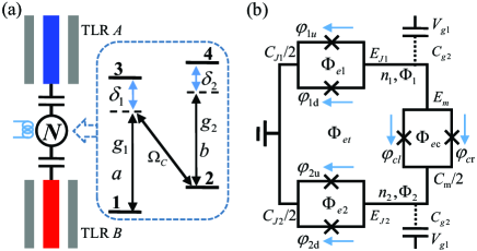
The schematic diagram for realizing the cross-Kerr effect between two TLRs is shown in Fig. 1. The cross-Kerr effect can be realized by coupling two TLRs to a four level N-type superconducting molecule as shown in Fig. 1(a). The level structure is depicted in the dashed line box. TLR A and TLR B are coupled to the levels and , respectively. The transition between the levels and is driven by a classical pump laser with the strength . In the interaction picture, the Hamiltonian of the whole interaction system is given by YHu (with )
| (1) | |||||
where the detunings are and . and are the frequencies of the TLRs A and B, respectively. is the transition operator from the states to . and are the annihilation (creation) operators for the modes of TLRs A and B, respectively. and are the coupling strengths for corresponding interactions between TLRs and levels. Under the conditions that and AImamoglu1997 , one can adiabatically eliminate the atomic degrees of freedom and obtain the effective cross-Kerr interaction Hamiltonian YHu
| (2) |
where is the cross-Kerr coefficient.
The molecule with an N-type level structure can be constructed in the superconducting circuit described in Fig. 1(b). The two loops (bottom and top) are two transmon qubits JKoch . The right loop is a superconducting quantum interference device (SQUID) JSiewert which is used to connect two transmon qubits. Each loop is composed of two identical Josephson junctions labeled with crosses. and represent the capacitance and energy of the Josephson junctions, respectively. The gate voltages labeled with and bias the corresponding transmons via the gate capacitors and , respectively. , , , and are external fluxes. , , , , , and are the gauge-invariant phases across the Josephson junctions. By using the two-level language in the region , one can obtain the -type level form YHu ; JKoch shown in Fig. 1(a). The eigenstates and the corresponding eigenvalues are and , respectively.
II.2 The Quantum nondemolition measurement on total photon number of transmission-line resonators based on cross-Kerr effect
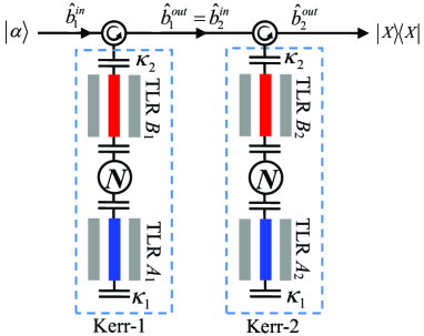
The total photon number of TLRs can be measured with QND by means of the cross-Kerr effect. The detailed schematic diagram is shown in Fig. 2. All the TLRs in the top and the bottom are the readout and storage resonators, respectively. The Homedyne detection has been used for microwave in circuit QED experiment RVijaynature . The probe light in the coherent state is input from the left and measured via an homodyne measurement on the right. Here, we use the input-output relationship to explain the whole process. When the probe light is resonant with readout resonators, the Heisenberg-Langevin equations for each cross-Kerr media in the probe light path are given by
| (3) |
where , and represents the photon number operator of the -th storage resonator. We assume that all TLRs labeled with A and B have the same decay rates and , respectively.
Now, we consider the situation that the decay rate of the readout resonator . One can make in Eq. (3). Combining with the standard cavity input-output relationship DFWalls ; Kevin , where and satisfy the standard commutation relations , one can obtain the reflection coefficients which are expressed as
| (4) |
Our goal is to make a QND measurement on the total photon number in two storage resonators (the two TLRs and in the bottom of Fig. 2). For this task, a probe light in the coherent state is input from the left, and let us assume that there are photons in TLR . When the probe light leaves TLR , the state of Kerr-1 becomes
| (5) |
Here arg and is a Fock state. One can make an homodyne measurement to infer the photon number in TLR because the phase shift depends on the photon number . When the probe light passes through TLR , two Kerr media become a cascaded system. Therefore, we set because the input field of resonator is the output field of resonator . The input-output relationship of this cascaded system is . Let us assume that the photon number in TLR is . After the probe light leaves resonator , its state is given by
| (6) |
where
| (7) |
where .
To make an effective homodyne detection, we detect the position quadrature of the coherent state. The wave function in the coherent state is given by KNemotoprl2004 ; SDBarrettpra
| (8) |
where the functions are given by
| (9) | |||||
Therefore, for states and , the midpoint and distance between the peaks of corresponding functions and are and , respectively. According to the result of position, one can distinguish the different phases. The error probability is given by SDBarrettpra
| (10) |
where is the complementary error function.
When we only consider the maximal total photon number of two, all the different Fock states and corresponding phase shifts are shown in Table 1.
| Total phase shift | |||||||||||||||||||||||||||||||||
|---|---|---|---|---|---|---|---|---|---|---|---|---|---|---|---|---|---|---|---|---|---|---|---|---|---|---|---|---|---|---|---|---|---|
III Entanglement purification of bit-flipping errors for microwave photons
III.1 Entanglement purification protocol for microwave-photon pairs
Let us assume that the nonlocal microwave-photon pairs in quantum communication are in the mixed state described by
| (11) |
where
| (12) |
and represent the horizontal and the vertical polarizations of microwave photons, respectively. The symbol with the relationship is the fidelity of the state (). In this way, the state of the system composed of two microwave-photon pairs is just the mixture of four states. They are with a probability of , and with the same probability of , and with a probability of .
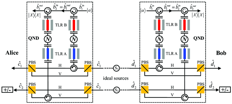
The principle of our EPP for the polarization entanglement of nonlocal microwave-photon pairs from two identical ideal entanglement sources is shown in Fig. 3. Here, we choose two same cross-Kerr systems, i.e., , to accomplish the QND measurement process for parity check. We will discuss the physical implementation in Sec. III.3. The microwave polarizing beam splitter (PBS) shown in Fig. 3 can pass the photons in the state and reflect the photons in the state . Therefore, in the QND part of this protocol, we can change and to and for , respectively. For , and can be represented by and , respectively. The different polarization states and corresponding phase shifts are rewritten in Table 2. The two QND measurement detectors are identical and the two parties in quantum communication Alice and Bob hold and , respectively. We don’t consider the phase difference of microwave photon after it leaves the storage resonator in our scheme, because we just design the principle here. The possible phase difference can be compensated in practice.
| () | Total phase shift | |||||||||||||||||||||||
|---|---|---|---|---|---|---|---|---|---|---|---|---|---|---|---|---|---|---|---|---|---|---|---|---|
When the microwave-photon pairs in the state pass through the parity-check QND detectors, the state of the composite system composed of the two microwave-photon pairs ( and ) and the two probe lights ( and ) becomes
| (13) | |||||
When Alice and Bob obtain a phase shift with on their coherent states after the homodyne detections, the state will collapse to . For the last two terms, there are two situations. If , the last two terms have the same phase shifts. At this point, both Alice and Bob obtain the phase shift on their coherent states, the state becomes . Subsequently, Alice and Bob can perform a bit-flipping operation on and , respectively, and then they can obtain the state . If the , Alice and Bob will obtain the different results, they will make no operation. To get the state , Alice and Bob make a measurement with the diagonal basis on and , respectively. When both their results are or , the state of the microwave-photon pair becomes . Otherwise, they should make the operation on the microwave photon to obtain the state .
After the QND measurement process, the state of the system becomes
| (14) | |||||
Another state is evolved to
| (15) | |||||
From these two results, with the situation , one can see that if Alice and Bob obtain the phase shifts and with a homodyne measurement on their probe lights and , the state of the two microwave-photon pairs becomes or . As Alice and Bob cannot determine on which pair a bit-flipping error occurs, they discard both photon pairs in these two situations. With the situation , Alice and Bob get the different results for all the terms. They should also discard all these situations.
After the microwave-photon pairs pass through the QND detectors, the state of the system turns to
| (16) | |||||
The result is similar to that in the situation with no bit-flipping error expressed in Eq. (13). Due to the indistinguishability with the situation with no bit-flipping errors, Alice and Bob should keep their photon pairs for the next round. That is, if Alice and Bob get the phase shift , they obtain the state of the two photon pairs . If they both get the phase shift (condition ), they get the state . Therefore, they make an operation on and to obtain the state . Subsequently, Alice and Bob make a measurement with the diagonal basis on and . If they both obtain the results or , the state of microwave-photon pairs becomes . Otherwise, they should make the operation on the microwave photon to obtain the state .
After the operations, Alice and Bob can obtain their nonlocal entangled state of microwave-photon pairs with more purity. In the ideal model, the fidelity of the remaining microwave-photon pairs is given by
| (17) |
| State | Total phase shift | ||||||||||||||||||||||||||||
|---|---|---|---|---|---|---|---|---|---|---|---|---|---|---|---|---|---|---|---|---|---|---|---|---|---|---|---|---|---|
III.2 Entanglement purification for polarization-spatial entangled microwave-photon pairs
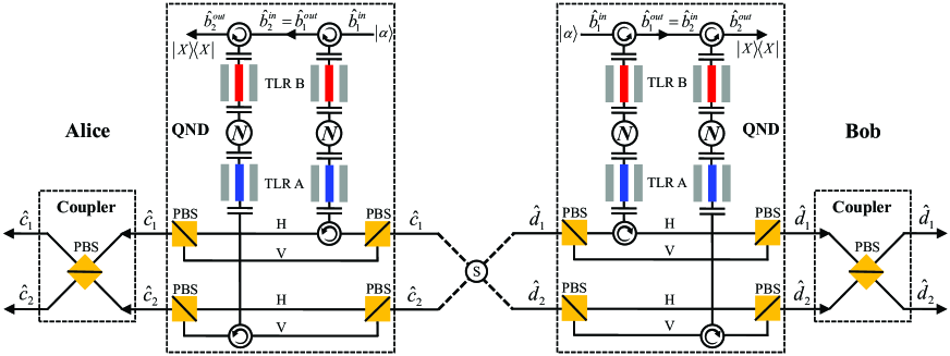
The polarization-spatial entangled states are widely used in quantum communication as they can be produced by parametric down-conversion naturally in experiment. Therefore, considering the situation for polarization-spatial entangled microwave-photon pairs is very necessary. For a pair polarization-spatial entangled microwave photons, the state is given by . Therefore, for the four-photon state, it can be described by . The detailed schematic diagram of our EPP for those two situations is shown in Fig. 4. Here the states and are translated to and in mode, respectively. In mode, the corresponding relations are opposite. Here, we choose the two same cross-Kerr systems in each QND detector and the corresponding phase shifts are given in Table 3. We assume all the four angles are different in this section.
First, we consider the case where there is a pair of polarization-spatial entangled microwave photons. This time, it is just an ideal microwave-photon pair. After it passes through the QND detectors, the state composed of the microwave-photon pair and the probe light is given by
| (18) | |||||
When Alice and Bob get the same phase shift via an X homodyne measurement on their probe lights, they obtain the state of their microwave-photon pair . After passing through the couplers, their photon pair will appear at the modes . When Alice and Bob get the same phase shift , they obtain the state , and then their photon pair will appear at the output modes . When the bit-flipping error occurs, the state becomes . With the QND measurement, the state of the photon pair evolves to
| (19) | |||||
Alice and Bob will get the different results and . They should perform a bit-flip operation of polarization on photon to obtain the state .
Second, we consider the case where there are two pairs of polarization-spatial entangled microwave photons. With no decoherence, the state of the two photon pairs is expressed as . After the QND measurements are performed by Alice and Bob, the state of the whole system composed of the photon pair and the probe lights is
| (20) | |||||
Alice and Bob will get four results with , , , and which correspond to the states , , , and , respectively. After the photons pass through the couplers, the states and will appear at and , respectively. The two photon pairs will be divided into and , respectively.
When the bit-flipping error occurs, there will be two situations. The first situation is that only one of two microwave-photon pairs has an error, and the state of the two photon pairs becomes . Therefore, with the QND detector, the composite system composed of the two photon pairs and the two probe lights evolves to
| (21) | |||||
Analyzing from the result in Eq. (21), Alice and Bob know there exists an error in one pair when they get the different phase shifts. Alice and Bob should discard this result because they cannot get the state at and .
The second one is the bit-flipping error taking place on both the two microwave photon pairs. The state becomes . When the two pairs pass the QND detectors, the state of the system will evolve to
| (22) | |||||
Alice and Bob get the five results in which four results have different phase shifts and the other has the same phase shift. For the different phase shifts, they should discard the photon pairs because the pairs will appear in the same spatial mode. When Alice and Bob get the same phase shift, they cannot distinguish it from the situation with no error and they should keep the pairs. Then Alice and Bob can continue to purify the states by using the protocol presented for ideal entanglement sources discussed in Sec. III.1.
III.3 Parameters and fidelity for quantum nondemolition detector
The cross-Kerr effect is induced by coupling two TLRs to a superconducting molecule as shown in Fig. 1. According to the previous works HZhangPRA2017 ; YHu , we choose the parameters of this superconducting system as GHz, GHz, and GHz. The two coupling strengthes between the molecule and the TLRs are equal with MHz. The classical pump field strength and the detuning are designed to GHz. Therefore, the cross-Kerr effect coefficient in our scheme is MHz. A recent experiment ETHolland demonstrated a state-dependent shift MHz between two cavities in circuit QED.
According to the parameters chosen above, we calculate the angle of the coherent state in Table 3. The angles of states , , and are , , and , respectively. Here, we choose the decay rate with ns in our calculation. If we require that the minimal error probability is less than 0.01, according to the Eq. (10), then should satisfy . Therefore, when the satisfies , all the angles can be distinguished. Here, the cross-Kerr effect is weak, the phase shifts in Table 2 can not satisfy the condition . Therefore, in this physical system, Alice and Bob should make operations under the situation with different phase shifts.

In practice, the number of microwave photons will decrease due to the dissipation of storage resonators. The dynamics of the quantum system with dissipation is described by the master equation in Lindblad form given by
| (23) |
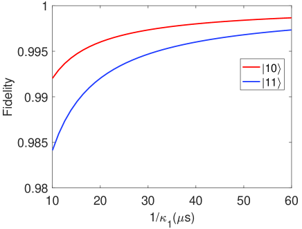
where and are the density matrix and the Hamiltonian of the system, respectively. The symbols represents the decay rates of TLR A. The superoperator with the rule represents the influence of the dissipation. Here, we assume that the QND measurement is ideal and that the probe light has no influence on the states in storage resonators. The fidelity is influenced by the leakage of the resonator. The formula of fidelity is , where the ideal state is the initial state here. We consider the two initial states with and . State represents and photons in storage resonator and , respectively. We calculate the fidelities of the states in storage resonators at the end of the measuring time. In the rotating frame, the Hamiltonian of the resonator is zero. We choose the total measuring time of the cascade system with . The decay rate of the readout resonator keeps ns in the whole process. The fidelities are proportional to in Fig. 5, which indicates that the large storage time (the better resonator) can protect the microwave photons from dissipation. Then we plot the influences from the different in Fig. 6. The parameter here is s. Contrary to Fig. 5, the fidelities are inversely proportional to in Fig. 6. The large means a long measuring time. Therefore, as becomes large, it will result in more total dissipation and the fidelity becomes lower.
IV summary
In summary, we have proposed a physically feasible polarization EPP for the entangled state of nonlocal microwave photons in circuit QED. Our EPP includes two processes. The first process is used to purify the polarization entanglement state generated by the ideal entanglement sources and the second process is used for polarization-spatial entangled microwave-photon pairs. In our EPP, we design the polarization parity-check QND detectors to realize the postselection of microwave-photon quantum states. According to the phase shifts of the probe light hold by the two remote parties in quantum communication, say Alice and Bob, the parties can distinguish whether the error takes place and then correct it. We implement the QND measurement based on the cross-Kerr effect induced by coupling the two TLRs to a superconducting molecule. Our work can improve the practical application of microwave-based quantum communication. For example, quantum repeaters are the indispensable parts in long-distance quantum communication. Due to the unavoidable influence of the environment in the processes of transmission and storage, the nonlocal near maximally entangled state generated between every two neighboring nodes and used as the quantum channel in a quantum repeater may turn into a mixed entangled state. Therefore, our purification protocol can be used here. Also, in the actual situation of satellite quantum communication, when the microwave signals pass through the aerosphere from the quantum satellite to the ground, the pure maximally entangled microwave-photon state may become the mixed one due to the influence of environment in the process of satellite quantum communication. To keep the communication efficient, the parties can use our EPP to purify the mixed entangled microwave-photon state to improve its fidelity.
ACKNOWLEDGMENTS
We thank Guan-Yu Wang, Jing Qiu, and Zhi-Sheng Yang for helpful
discussions. This work is supported by the National Natural Science
Foundation of China under Grants No. 11674033, No. 11474026, and No.
11474027, the Fundamental Research Funds for the Central
Universities under Grant No. 2015KJJCA01, and the National Key
Basic Research Program of China under Grant No. 2013CB922000.
References
- (1) C. H. Bennett, G. Brassard, C. Crepeau, R. Jozsa, A. Peres, and W. K. Wootters, Teleporting an Unknown Quantum State via Dual Classical and Einstein-Podolsky-Rosen Channels, Phys. Rev. Lett. 70, 1895 (1993).
- (2) C. H. Bennett and S. J. Wiesner, Communication via One- and Two-Particle Operators on Einstein-Podolsky-Rosen states, Phys. Rev. Lett. 69, 2881 (1992).
- (3) X. S. Liu, G. L. Long, D. M. Tong, and F. Li, General scheme for superdense coding between multiparties, Phys. Rev. A 65, 022304 (2002).
- (4) A. K. Ekert, Quantum Cryptography Based on Bell’s Theorem, Phys. Rev. Lett. 67, 661 (1991).
- (5) C. H. Bennett, G. Brassard, and N. D. Mermin, Quantum Cryptography Without Bell’s Theorem, Phys. Rev. Lett. 68, 557 (1992).
- (6) X. H. Li, F. G. Deng, and H. Y. Zhou, Efficient quantum key distribution over a collective noise channel, Phys. Rev. A 78, 022321 (2008).
- (7) M. Hillery, V. Bužek, and A. Berthiaume, Quantum secret sharing, Phys. Rev. A 59, 1829 (1999).
- (8) G. L. Long and X. S. Liu, Theoretically efficient high-capacity quantum-key-distribution scheme, Phys. Rev. A 65, 032302 (2002).
- (9) F. G. Deng, G. L. Long, and X. S. Liu, Two-step quantum direct communication protocol using the Einstein-Podolsky-Rosen pair block, Phys. Rev. A 68, 042317 (2003).
- (10) C. Wang, F. G. Deng, Y. S. Li, X. S. Liu, and G. L. Long, Quantum secure direct communication with high-dimension quantum superdense coding, Phys. Rev. A 71, 044305 (2005).
- (11) W. Zhang, D. S. Ding, Y. B. Sheng, L. Zhou, B. S. Shi, and G. C Guo, Quantum secure direct communication with quantum memory, Phys. Rev. Lett. 118, 220501 (2017).
- (12) Z. D. Walton, A. F. Abouraddy, A. V. Sergienko, B. E. A. Saleh, and M. C. Teich, Decoherence-Free Fubspaces in Quantum Key Distribution, Phys. Rev. Lett. 91, 087901 (2003).
- (13) J. C. Boileau, D. Gottesman, R. Laflamme, D. Poulin, and R. W. Spekkens, Robust Polarization-Based Quantum Key Distribution Over a Collective-Noise Channel, Phys. Rev. Lett. 92, 017901 (2004).
- (14) J. C. Boileau, R. Laflamme, M. Laforest, and C. R. Myers, Robust Quantum Communication Using a Polarization-Entangled Photon Pair, Phys. Rev. Lett. 93, 220501 (2004).
- (15) C. H. Bennett, H. J. Bernstein, S. Popescu, and B. Schumacher, Concentrating partial entanglement by local operations, Phys. Rev. A 53, 2046 (1996).
- (16) Y. B. Sheng, F. G. Deng, and H. Y. Zhou, Nonlocal entanglement concentration scheme for partially entangled multipartite systems with nonlinear optics, Phys. Rev. A 77, 062325 (2008).
- (17) B. C. Ren, F. F. Du, and F. G. Deng, Hyperentanglement concentration for two-photon four-qubit systems with linear optics, Phys. Rev. A 88, 012302 (2013).
- (18) X. H. Li and S. Ghose, Hyperentanglement concentration for time-bin and polarization hyperentangled photons, Phys. Rev. A 91, 062302 (2015).
- (19) H. Zhang and H. Wang, Entanglement concentration of microwave photons based on the Kerr effect in circuit QED, Phys. Rev. A 95, 052314 (2017).
- (20) C. H. Bennett, G. Brassard, S. Popescu, B. Schumacher, J. A. Smolin, and W. K. Wootters, Purification of Noise Entanglement and Faithful Teleportation via Noisy Channels, Phys. Rev. Lett. 76, 722 (1996).
- (21) D. Deutsch, A. Ekert, R. Jozsa, C. Macchiavello, S. Popescu, and A. Sanpera, Quantum Privacy Amplification and the Security of Quantum Cryptography over Noisy Channels, Phys. Rev. Lett. 77, 2818 (1996).
- (22) J. W. Pan, C. Simon, C. Brukner, and A. Zelinger, Entanglement purification for quantum communication, Nature (London) 410, 1067 (2001).
- (23) C. Simon and J.W. Pan, Polarization Entanglement Purification using Spatial Entanglement, Phys. Rev. Lett. 89, 257901 (2002).
- (24) J. W. Pan, S. Gasparoni, R. Ursin, G. Weihs, and A. Zeilinger, Experimental entanglement purification of arbitrary unknown states, Nature (London) 423, 417 (2003).
- (25) Y. B. Sheng, F. G. Deng, and H. Y. Zhou, Efficient polarization-entanglement purification based on parametric down-conversion sources with cross-Kerr nonlinearity, Phys. Rev. A 77, 042308 (2008).
- (26) Y. B. Sheng and F. G. Deng, Deterministic entanglement purification and complete nonlocal Bell-state analysis with hyperentangledment, Phys. Rev. A 81, 032307 (2010).
- (27) Y. B. Sheng and F. G. Deng, One-step deterministic polarization-entanglement purification using spatial entanglement, Phys. Rev. A 82, 044305 (2010).
- (28) X. H. Li, Deterministic polarization-entanglement purification using spatial entanglement, Phys. Rev. A 82, 044304 (2010).
- (29) F. G. Deng, One-step error correction for multipartite polarization entanglement, Phys. Rev. A 83, 062316 (2011).
- (30) B. C. Ren, F. F. Du, and F. G. Deng, Two-step hyperentanglement purification with the quantum-state-joining method, Phys. Rev. A 90, 052309 (2014).
- (31) G. Y. Wang, Q. Liu, and F. G. Deng, Hyperentanglement purification for two-photon six-qubit quantum systems, Phys. Rev. A 94, 032319 (2016).
- (32) C. Wang, Y. Zhang, and G. S. Jin, Entanglement purification and concentration of electron-spin entangled states using quantum-dot spins in optical microcavities, Phys. Rev. A 84, 032307 (2011).
- (33) Y. B. Sheng and L. Zhou, Deterministic polarization entanglement purification using time-bin entanglement, Laser Phys. Lett. 11, 085203 (2014).
- (34) Y. B. Sheng and L. Zhou, Deterministic entanglement distillation for secure double-server blind quantum computation, Sci. Rep. 5, 7815 (2015).
- (35) R. F. Werner, Quantum states with Einstein-Podolsky-Rosen correlations admitting a hidden-variable model, Phys. Rev. A 40, 4277 (1989).
- (36) A. Blais, R. S. Huang, A. Wallraff, S. M. Girvin, and R. J. Schoelkopf, Cavity quantum electrodynamics for superconducting electrical circuits: An architecture for quantum computation, Phys. Rev. A 69, 062320 (2004).
- (37) A. Wallraff, D. I. Schuster, A. Blais, L. Frunzio, R. S. Huang, J. Majer, S. Kumar, S. M. Girvin, and R. J. Schoelkopf, Strong coupling of a single photon to a superconducting qubit using circuit quantum electrodynamics, Nature (London) 431, 162 (2004).
- (38) A. Blais, J. Gambetta, A. Wallraff, D. I. Schuster, S. M. Girvin, M. H. Devoret, and R. J. Schoelkopf, Quantum-information processing with circuit quantum electrodynamics, Phys. Rev. A 75, 032329 (2007).
- (39) L. DiCarlo, J. M. Chow, J. M. Gambetta, Lev S. Bishop, B. R. Johnson, D. I. Schuster, J. Majer, A. Blais, L. Frunzio, S. M. Girvin, and R. J. Schoelkopf, Demonstration of two-qubit algorithms with a superconducting quantum processor, Nature (London) 460, 240 (2009).
- (40) Y. Cao, W. Y. Huo, Q. Ai, and G. L. Long, Theory of degenerate three-wave mixing using circuit QED in solid-state circuits, Phys. Rev. A 84, 053846 (2011).
- (41) H. Wang, M. Mariantoni, R. C. Bialczak, M. Lenander, E. Lucero, M. Neeley, A. D. O’Connell, D. Sank, M. Weides, J. Wenner, T. Yamamoto, Y. Yin, J. Zhao, J. M. Martinis, and A. N. Cleland, Deterministic entanglement of photons in two superconducting microwave resonators, Phys. Rev. Lett. 106, 060401 (2011).
- (42) Y. Hu and L. Tian, Deterministic generation of entangled photons in superconducting resonator arrays, Phys. Rev. Lett. 106, 257002 (2011).
- (43) A. Fedorov, L. Steffen, M. Baur, M. P. da Silva, and A. Wallraff, Implementation of a Toffoli gate with superconducting circuits, Nature (London) 481, 170 (2012).
- (44) M. D. Reed, L. DiCarlo, S. E. Nigg, L. Sun, L. Frunzio, S. M. Girvin, and R. J. Schoelkopf, Realization of three-qubit quantum error correction with superconducting circuits, Nature (London) 482, 382 (2012).
- (45) R. Vijay, C. Macklin, D. H. Slichter, S. J. Weber, K. W. Murch, R. Naik, A. N. Korotkov, and I. Siddiqi, Stabilizing Rabi oscillations in a superconducting qubit using quantum feedback, Nature (London) 490, 77 (2012).
- (46) F. W. Strauch, All-resonant control of superconducting resonators, Phys. Rev. Lett. 109, 210501 (2012).
- (47) D. I. Schuster, A. A. Houck, J. A. Schreier, A. Wallraff, J. M. Gambetta, A. Blais, L. Frunzio, J. Majer, B. Johnson, M. H. Devoret, S. M. Girvin, and R. J. Schoelkopf, Resolving photon number states in a superconducting circuit, Nature (London) 445, 515 (2007).
- (48) A. A. Houck, D. I. Schuster, J. Gambetta, J. A. Schreier, B. R. Johnson, J. M. Chow, L. Frunzio, J. Majer, M. H. Devoret, S. M. Girvin, and R. J. Schoelkopf, Generating single microwave photons in a circuit, Nature (London) 449, 328 (2007).
- (49) J. Majer, J. M. Chow, J. M. Gambetta, J. Koch, B. R. Johnson, J. A. Schreier, L. Frunzio, D. I. Schuster, A. A. Houck, A. Wallraff, A. Blais, M. H. Devoret, S. M. Girvin, and R. J. Schoelkopf, Coupling superconducting qubits via a cavity bus, Nature (London) 449, 443 (2007).
- (50) M. Hofheinz, E. M. Weig, M. Ansmann, R. C. Bialczak, E. Lucero, M. Neeley, A. D. O’Connel, H. Wang, J. M. Martinis, and A. N. Cleland, Generation of Fock states in a superconducting quantum circuit, Nature (London) 454, 310 (2008).
- (51) B. R. Johnson, M. D. Reed, A. A. Houck, D. I. Schuster, Lev S. Bishop, E. Ginossar, J. M. Gambetta, L. DiCarlo, L. Frunzio, S. M. Girvin and R. J. Schoelkopf, Quantum non-demolition detection of single microwave photons in a circuit, Nat. Phys. 6, 663 (2010).
- (52) M. Hua, M. J. Tao, and F. G. Deng, Universal quantum gates on microwave photons assisted by circuit quantum electrodynamics, Phys. Rev. A 90, 012328 (2014).
- (53) A. Narla, S. Shankar, M. Hatridge, Z. Leghtas, K. M. Sliwa, E. Zalys-Geller, S. O. Mundhada, W. Pfaff, L. Frunzio, R. J. Schoelkopf, and M. H. Devoret, Robust Concurrent Remote Entanglement Between Two Superconducting Qubits, Phys. Rev. X 6, 031036 (2016).
- (54) S. Rebić, J. Twamley, and G. J. Milburn, Giant Kerr nonlinearities in circuit quantum electrodynamics, Phys. Rev. Lett. 103, 150503 (2009).
- (55) S. Kumar and D. P. DiVincenzo, Exploiting Kerr cross nonlinearity in circuit quantum electrodynamics for nondemolition measurements, Phys. Rev. B 82, 014512 (2010).
- (56) Y. Hu, G. Q. Ge, S. Chen, X. F. Yang, and Y. L. Chen, Cross-Kerr-effect induced by coupled Josephson qubits in circuit quantum electrodynamics, Phys. Rev. A 84, 012329 (2011).
- (57) G. Kirchmair, B. Vlastakis, Z. Leghtas, S. E. Nigg, H. Paik, E. Ginossar, M. Mirrahimi, L. Frunzio, S. M. Girvin, and R. J. Schoelkopf. Observation of quantum state collapse and revival due to the single-photon Kerr effect, Nature (London) 495, 205 (2013).
- (58) I. C. Hoi, A. F. Kockum, T. Palomaki, T. M. Stace, B. Fan, L. Tornberg, S. R. Sathyamoorthy, G. Johansson, P. Delsing, and C. M. Wilson, Giant cross-Kerr effect for propagating microwaves induced by an artificial atom, Phys. Rev. Lett. 111, 053601 (2013).
- (59) E. T. Holland, B. Vlastakis, R. W. Heeres, M. J. Reagor, U. Vool, Z. Leghtas, L. Frunzio, G. Kirchmair, M. H. Devoret, M. Mirrahimi and R. J. Schoelkopf, Single-photon-resolved cross-Kerr interaction for autonomous stabilization of photon-number states, Phys. Rev. Lett. 115, 180501 (2015).
- (60) J. M. Hao, Y. Yuan, L. X. Ran, T. Jiang, J. A. Kong, C. T. Chan, and L. Zhou, Manipulating electromagnetic wave polarizations by anisotropic metamaterials, Phys. Rev. Lett. 99, 063908 (2007).
- (61) D. R. Solli, C. F. McCormick, R. Y. Chiao, and J. M. Hickmann, Photonic crystal polarizers and polarizing beam splitters, J. Appl. Phys. 93, 9429 (2003).
- (62) J. Koch, T. M. Yu, J. M. Gambetta, A. A. Houck, D. I. Schuster, J. Majer, A. Blais, M. H. Devoret, S. M. Girvin, and R. J. Schoelkopf, Charge-insensitive qubit design derived from the Cooper pair box, Phys. Rev. A 76, 042319 (2007).
- (63) J. Siewert, R. Fazio, G. M. Palma, and E. Sciacca, Aspects of qubit dynamics in the presence of leakage, J. Low Temp. Phys. 118, 795 (2000).
- (64) A. Imamoǧlu, H. Schmidt, G. Woods, and M. Deutsch, Strongly Interacting Photons in a Nonlinear Cavity, Phys. Rev. Lett. 79, 1467 (1997).
- (65) D. F. Walls and G. J. Milburn, Quantum Optics (Springer-Verlag, Berlin, 1994).
- (66) K. Lalumière, B. C. Sanders, A. F. van Loo, A. Fedorov, A. Wallraff, and A. Blais, Input-output theory for waveguide QED with an ensemble of inhomogeneous atoms, Phys. Rev. A 88, 043806 (2013).
- (67) K. Nemoto and W. J. Munro, Nearly Deterministic Linear Optical Controlled-NOT Gate, Phys. Rev. Lett. 93, 250502 (2004).
- (68) S. D. Barrett, P. Kok, K. Nemoto, R. G. Beausoleil, W. J. Munro, and T. P. Spiller, Symmetry analyzer for nondestructive Bell-state detection using weak nonlinearities, Phys. Rev. A 71, 060302(R) (2005).