55email: tibai@fizika.ttk.pte.hu
Laser-plasma accelerator based single-cycle attosecond undulator source
Abstract
Laser-plasma accelerators (LPAs), producing high-quality electron beams, provide an opportunity to reduce the size of free-electron lasers (FELs) to only a few meters. A complete system is proposed here, which is based on FEL technology and consists of an LPA, two undulators, and other magnetic devices. The system is capable to generate carrier-envelope phase stable attosecond pulses with engineered waveform. Pulses with up to 60 nJ energy and 90 to 400 attosecond duration in the 30 to 120 nm wavelength range are predicted by numerical simulation. These pulses can be used to investigate ultrafast field-driven electron dynamics in matter.
OCIS codes: 140.2600, 320.0320
1 Introduction
The time-resolved study of electron dynamics in atoms, molecules, and solids require attosecond-scale temporal resolution HentschelNat2001 ; KienbergerNat2004 ; SchaferPRL2004 ; JohnssonPRL2005 ; KrauszRMP2009 . A suitable tool is provided by isolated attosecond pulses in the extreme ultraviolet (EUV) spectral range, produced by high-harmonic generation (HHG) of waveform-controlled few-cycle laser pulses. The recent demonstration of single-cycle isolated attosecond pulses KrauszRMP2009 may open the way to a new regime in ultrafast physics, where the strong-field electron dynamics is driven by the electric field of the attosecond pulses rather than by their intensity profile. Intense EUV pulses can also be generated in free-electron lasers (FELs), which are expensive large-scale facilities relying on linear accelerators (LINACs). In recent years, many ideas have been proposed to achieve ultrashort pulses in FELs EmmaPRL2004 ; ZholentsPRST2005 ; DunningPRL2013 ; GarciaPRAB2016 ; TanakaPRL2015 ; SansoneSci2006 . However, the limited temporal coherence of the radiation remained a serious drawback for many applications.
Laser-plasma based electron accelerators (LPAs) TajimaPRL1979 ; ManglesNature2004 ; GeddesNature2004 ; FaureNature2004 ; MalkaNP2008 ; EsareyRMP2009 ; WangNC2013 can be a cost-effective alternative for large-scale LINACs, allowing a tremendous reduction of the accelerator size. It is possible to reach electron energies up to the GeV level over acceleration distances of only a few cm in a wakefield LPA with parameters comparable to (and in some aspects even better than) conventional LINAC sources EsareyRMP2009 ; WangNC2013 ; LeemansNP2006 . The electron beam transversal size in a LPA can be more than two orders of magnitude smaller (m) than typical for LINACs. The peak current in a LPA can be one order of magnitude higher than in a conventional LINAC. Such unique properties of LPA electron pulses offer the potential to construct FELs with a significantly reduced overall dimension and cost, thereby enabling a widespread proliferation of FEL sources to small-scale university labs. Owing to these advantages, numerous schemes have been proposed to use LPA electrons to drive FEL sources CoupriePPCF2016 ; TilborgAIPCP2017 ; LiuPRAB2017 ; NakajimaNP2008 ; FuchsNP2009 ; CouprieJPB2014 ; CouprieJMO2016 ; FengOE2015 .
Remarkably, none of the previously mentioned techniques, whether HHG-, LPA-, or LINAC-based, could so far produce waveform-engineered CEP-controlled attosecond pulses. Therefore, previously we proposed a robust method for producing such EUV pulses using conventional LINAC-based FEL technology TibaiPRL2014 ; TothOL2015 ; TibaiArxiv2016 . Motivated by the exciting recent progresses in high-power lasers and LPAs delivering high-quality electron beams, here we investigate the feasibility and the prospects of adopting our previous concept to be driven by an LPA, rather than a LINAC. A detailed conceptual study is presented, based on numerical simulations, for an entirely laser-driven waveform-engineered CEP-controlled attosecond pulse source.
2 The proposed setup
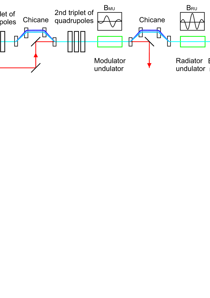
The proposed setup for an LPA-based waveform-engineered attosecond pulse source is shown in Fig. 1. Laser pulses of at least 100 TW-power are split into two separate beams. The main part is focused into a gas-filled capillary for producing a relativistic electron beam EsareyRMP2009 ; LeemansNP2006 . After the LPA, the electron beam is sent through the first triplet of quadrupoles to reduce its divergence. Subsequently, a chicane reduces the slice energy spread of the beam. The following second triplet of quadrupoles is used to focus the electron beam into the radiator undulator (RU), which is placed further downstream in the setup. The second quadrupole triplet is followed by the modulator undulator (MU), where the electron bunch is overlapped with the smaller, 20-TW portion of the laser beam. Here, the interaction between the electrons, the magnetic field of the MU, and the electromagnetic field of the modulator laser introduces a spatially periodic energy modulation of the electrons. The electrons propagate through a second chicane and their energy modulation leads to the formation of a train of nanobunches (ultrathin electron layers), separated by the modulator laser wavelength. (The second chicane is used to reduce the propagation distance where the shortest nanobunches are formed.) The nanobunched electron beam then passes through the RU, consisting of a single or a few periods, and creates CEP-stable attosecond pulses.
3 Transport and manipulation of the electron beam
The General Particle Tracer (GPT) numerical code GPT was used for the simulation of the electron beam transport from the capillary to the RU. Due to limitations of computational capacity, macroparticles consisting of about 4100 electrons were considered, rather than individual electrons. The initial electron bunch parameters were chosen according to feasible parameters for LPA-generated electron beams EsareyRMP2009 ; LeemansNP2006 and are listed in Table 1. We performed a series of simulation runs, during which the electron bunch length was kept constant for each run, but the initial spatial distribution of the electrons was random. We note that particle-in-cell (PIC) simulations BussmannSC2013 can be used to implement more detailed predictions on the initial electron beam parameters, which then can serve as input for the particle-tracking calculations. However this is out of scope for the present work aiming at assessing the feasibility of the LPA-based CEP-stable attosecond source, rather than giving a complete in-depth numerical design and optimization study.
| Parameter | Value |
|---|---|
| Energy () | |
| Energy spread () | |
| Normalized emittance () | |
| Transversal size () | |
| Length () | |
| Charge |
Efficient generation of radiation is possible only if the (micro- or nano) bunch length is shorter than half of the radiation wavelength. If the Coulomb interaction between the electrons in the bunch can be neglected, the following analytical formula can be derived for the FWHM of the electron density of the micro- or nanobunch:
| (1) |
where is the wavelength of the modulator laser, is the energy spread of the nanobunch and is the induced energy gain in the MU HemsingRMP2014 ; Zholents2PRST2005 . According to this equation, shorter nanobunches can be achieved by using an electron beam with smaller energy spread and stronger energy modulation.
The energy spread of an LPA generated electron beam is typically much larger (1-10%) than that of a LINAC (typically 0.05%). Therefore, a reduction of the slice energy spread is necessary, which can be accomplished by the stretch of the beam or utilizing a transverse-gradient undulator (TGU) as a radiator HuangPRL2012 . In our setup we used the first chicane to decompress the beam longitudinally. The chicane consisted of four identical dipole magnets with parameters as listed in Table 2. The slice energy spread of the electron beam is reduced at the end of the chicane according to the formula CouprieJPCS2013
| (2) |
where is the length of the electron beam after the chicane, , is the distance between 1st (3rd) and 2nd (4th) dipoles, is the distance between 2nd and 3rd dipoles, and is the deviation angle at the dipoles. Hence, the electron bunch can be easily lengthened by adjusting the chicane strength (). The slice energy spread of the beam is reduced from 1% to 0.1% with mm, and the bunch is lengthened to about 10 m (33 fs).
| Parameter | Value |
|---|---|
| Dipole length | |
| Gap | |
| Dipole strength | |
| Distance between 1st (3rd) and 2nd (4th) dipoles () | |
| Distance between 2nd and 3rd dipoles () |
The modulator laser pulses are used for driving the nanobunch formation. As mentioned in the previous section, these laser pulses are provided by splitting off a small portion of the main beam. Our setup is very advantageous, because one common laser source creates the electron beam and the modulator laser beam, too. Therefore, the synchronization between the electron beam and the modulator laser pulses can be easily solved. Today, numerous 100-TW class laser systems are operating all around the world. For the split-off modulator laser pulses 20 TW peak power was assumed (Table 3). The MU period was chosen to satisfy the well-known resonance condition Wiedemann2003 at , where . Here, is the electron charge, is the magnetic field amplitude, is the electron rest mass, and is the speed of light. A double-period MU was assumed with antisymmetric design of , , , and relative magnetic field amplitudes. According to our calculations, the maximum energy modulation in the MU is . We note that the coherent synchrotron radiation effect may reduce the quality of the electron beam inside the MU and the chicanes. Although our estimations predicted that this effect is negligible, a more detailed investigation is planned using the SIMPLEX TanakaJSR2015 and the GENESIS ReicheNIMP1999 codes.
| Parameter | Value |
|---|---|
| Laser wavelength () | |
| Laser peak power | |
| Laser beam waist | |
| Laser beam Rayleigh length | |
| MU undulator parameter () | |
| MU period length () | |
| MU magnetic field amplitude () |
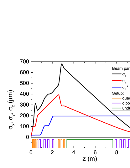
The location of the temporal focal point (where the nanobunch length becomes the shortest) was controlled with the second chicane. The total charge in a single nanobunch is about pC and its length is as short as 27 nm (FWHM). The RU was placed around the temporal focal point. The transversal focusing of the electron beam at the position of the RU was achieved with the two permanent-magnet quadrupole triplets with parameters as shown in Table 4. The gradients of them were optimized with GPT and a self-developed code. The calculated variations of transversal and longitudinal sizes of the whole electron bunch along the propagation direction are shown in Fig. 2. According to our calculations the transversal size of the electron-bunch at the RU in the and directions are 42 m and 68 m, respectively. As shown in Fig. 2, the variation of the transversal size of the bunch inside the RU is negligible.
| Parameters | Value | |
|---|---|---|
| Distance between the capillary and the 1st quadrupole | 15 | cm |
| 1st quadrupole triplet gradients | 197 / 177 / 73 | T/m |
| 1st chicane dipole field | 0.8 | T |
| 2nd quadrupole triplet gradients | 47 / 51 / 6 | T/m |
| 2nd chicane dipole field | 0.011 | T |
| RU undulator parameter () | 0.5, 0.8, and 1.2 | |
| RU undulator period length () | 43, 36, and 28 | cm |
4 Single cycle attosecond pulse generation
The temporal shape of the attosecond EUV pulses emitted by the extremely short nanobunches in the RU were calculated at a plane positioned 8 m behind the RU center. EUV waveform engineering is conveniently enabled by designing the magnetic field distribution of the RU. In the present case the magnetic field of the RU was defined as
| (3) |
where is the peak magnetic field, is the length along the direction of the nanobunch propagation, is the standard deviation of the Gaussian envelope, is the CEP and is the length of the RU. In each simulation series, the undulator period was adjusted to give the desired central wavelength for the radiation (20 nm, 30 nm, 40 nm, 60 nm, 80 nm, 100 nm, and 120 nm), according to the resonance equation. The further undulator parameters were set to , , and . (Similar magnetic field distribution has been demonstrated in the experiment of Kimura et al. KimuraPRST2004 .)
We used the following handbook formula to calculate the electric field of the radiation generated in the RU Jackson2007 :
| (4) |
where is the vacuum permeability, is the macroparticle charge, is the vector pointing from the position of the macroparticle at the retarded moment to the observation point, is the velocity of the macroparticle, , and is the speed of light. The summation is for all macroparticles. During the radiation process the position, velocity, and acceleration of the macroparticles were traced numerically by taking into account the Lorentz force of the magnetic field of RU. The Coulomb interaction between the macroparticles was neglected during the undulator radiation process, because the transversal electron motion is by four orders of magnitude larger than the motion generated by Coulomb interaction TibaiPRL2014 .
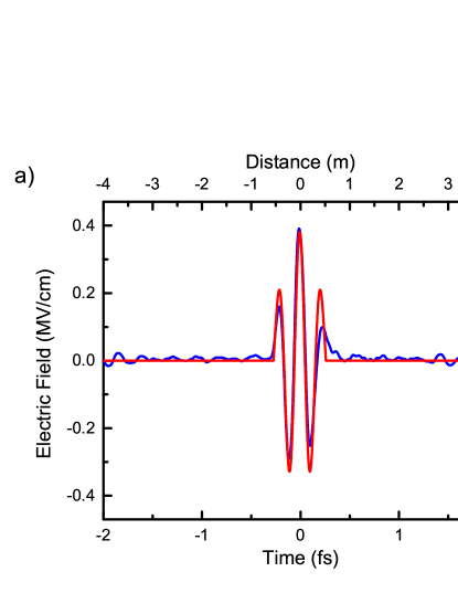
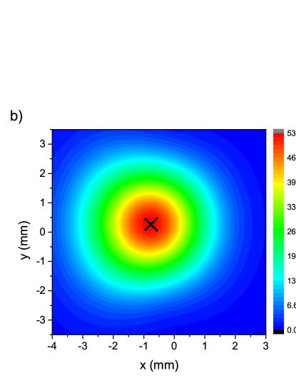
Figure 3a displays one example of the simulated waveform of the generated attosecond pulse (blue curve) and Figure 3b the corresponding beam profile for 60 nm radiation wavelength and (the cross symbol marks the location where the waveform in Fig. 3a was sampled). As it is shown in Fig. 3a, the waveform of the generated attosecond pulse resembles the magnetic field of the RU (red curve) TibaiPRL2014 . At other wavelengths the shapes of the attosecond pulses are nearly identical to the shape shown in Fig. 3a (blue curve). Besides the CEP stability of the EUV pulses, another important advantage of this setup is that the EUV pulse CEP can be controlled (set) by the magnetic field distribution of the RU TothNIMP2016 . Consequently, attosecond pulses with both single- and multi-cycle waveform can be generated with this technique.
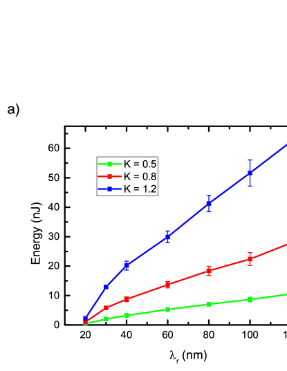
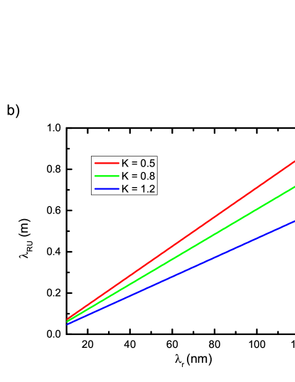
The EUV pulse energy as function of the radiation wavelength () in the range of 20 nm to 120 nm is shown in Fig. 4a, with three different RU undulator parameter values of 0.5, 0.8, and 1.2. These values correspond to 13 mT, 24 mT and 46 mT peak magnetic fields for nm. Larger EUV pulse energy is obtained with larger , because the energy of the pulse is proportional to the square of value. Fig. 4a contains the results of about 10 numerical simulation runs for every parameter set, determining also the error bars. The undulator parameter can be set to the desired value by adjusting the magnetic field amplitude. The radiation wavelength, given by the resonance condition, can be set by the choice of the RU period . The period of the RU as function of the radiation wavelength for different RU undulator parameters is shown in Fig. 4b. Our simulations predict attosecond pulses with up to 10 nJ, 25 nJ, and 60 nJ energy for undulator parameters of 0.5, 0.8, and 1.2, respectively (Fig. 4a). These energies are sufficient for many applications. Importantly, the LPA-based scheme does not require a large-scale accelerator facility and can be affordable for smaller laboratories.
5 Conclusion
A robust method for the efficient generation of CEP-stable single-cycle attosecond pulses was proposed, which utilizes a laser-plasma based electron accelerator, a modulator undulator, and a radiator undulator. The laser pulses used to drive the electron source and the nanobunching can be derived from the same laser, easily enabling the precise synchronization between the electrons and the modulating laser field. The waveform of the attosecond pulses can be engineered by the choice of the magnetic field distribution in the radiator undulator. A conceptual design study was presented, including also a combination of magnetic devices for electron beam transport and manipulation. The generation of single-cycle attosecond pulses in the EUV spectral range with up to 60 nJ energy was predicted by numerical simulations. The results clearly show that the previously proposed LINAC-based scheme can be adopted to an entirely laser-driven one, thereby enabling to shrink the size of the system from hundreds-of-meters to only a few meters, and a cost-effective implementation in small-scale laboratories. The source is suitable to deliver pump pulses in pump-probe measurements and in time- and CEP-resolved measurements with 100-as resolution.
Acknowledgements.
This work is partially supported by European Cluster of Advanced Laser Light Sources (EUCALL) project which has received funding from the European Union’s Horizon 2020 research and innovation programme under grant agreement No. 654220. Financial support from Hungarian Scientific Research Fund (OTKA) grant No. 113083 is acknowledged. JAF acknowledges support from János Bolyai Research Scholarship (Hungarian Academy of Sciences). The present scientific contribution is dedicated to the 650th anniversary of the foundation of University of Pécs, Hungary.References
- [1] M. Hentschel, R. Kienberger, Ch. Spielmann, G. A. Reider, N. Milosevic, T. Brabec, P. Corkum, U. Heinzmann, M. Drescher, and F. Krausz. Attosecond metrology. Nature, 414(6863):509–513, November 2001.
- [2] R. Kienberger, E. Goulielmakis, M. Uiberacker, A. Baltuska, V. Yakovlev, F. Bammer, A. Scrinzi, Th. Westerwalbesloh, U. Kleineberg, U. Heinzmann, M. Drescher, and F. Krausz. Atomic transient recorder. Nature, 427(6977):817–821, February 2004.
- [3] K. J. Schafer, M. B. Gaarde, A. Heinrich, J. Biegert, and U. Keller. Strong field quantum path control using attosecond pulse trains. Phys. Rev. Lett., 92:023003, Jan 2004.
- [4] P. Johnsson, R. López-Martens, S. Kazamias, J. Mauritsson, C. Valentin, T. Remetter, K. Varjú, M. B. Gaarde, Y. Mairesse, H. Wabnitz, P. Salières, Ph. Balcou, K. J. Schafer, and A. L’Huillier. Attosecond electron wave packet dynamics in strong laser fields. Phys. Rev. Lett., 95:013001, Jun 2005.
- [5] F. Krausz and M. Ivanov. Attosecond physics. Rev. Mod. Phys., 81:163–234, Feb 2009.
- [6] P. Emma, K. Bane, M. Cornacchia, Z. Huang, H. Schlarb, G. Stupakov, and D. Walz. Femtosecond and subfemtosecond x-ray pulses from a self-amplified spontaneous-emission–based free-electron laser. Phys. Rev. Lett., 92:074801, Feb 2004.
- [7] A. A. Zholents and G. Penn. Obtaining attosecond x-ray pulses using a self-amplified spontaneous emission free electron laser. Phys. Rev. ST Accel. Beams, 8:050704, May 2005.
- [8] D. J. Dunning, B. W. J. McNeil, and N. R. Thompson. Few-cycle pulse generation in an x-ray free-electron laser. Phys. Rev. Lett., 110:104801, Mar 2013.
- [9] B. Garcia, E. Hemsing, T. Raubenheimer, L. T. Campbell, and B. W. J. McNeil. Method to generate a pulse train of few-cycle coherent radiation. Phys. Rev. Accel. Beams, 19:090701, Sep 2016.
- [10] T. Tanaka. Proposal to generate an isolated monocycle x-ray pulse by counteracting the slippage effect in free-electron lasers. Phys. Rev. Lett., 114:044801, Jan 2015.
- [11] G. Sansone, E. Benedetti, F. Calegari, C. Vozzi, L. Avaldi, R. Flammini, L. Poletto, P. Villoresi, C. Altucci, R. Velotta, S. Stagira, S. De Silvestri, and M. Nisoli. Isolated single-cycle attosecond pulses. Science, 314(5798):443–446, 2006.
- [12] T. Tajima and J. M. Dawson. Laser electron accelerator. Phys. Rev. Lett., 43:267–270, Jul 1979.
- [13] S. P. D. Mangles, C. D. Murphy, Z. Najmudin, A. G. R. Thomas, J. L. Collier, A. E. Dangor, E. J. Divall, P. S. Foster, J. G. Gallacher, C. J. Hooker, D. A. Jaroszynski, A. J. Langley, W. B. Mori, P. A. Norreys, F. S. Tsung, R. Viskup, B. R. Walton, and K. Krushelnick. Monoenergetic beams of relativistic electrons from intense laser-plasma interactions. Nature, 431(7008):535–538, September 2004.
- [14] C. G. R. Geddes, Cs. Toth, J. van Tilborg, E. Esarey, C. B. Schroeder, D. Bruhwiler, C. Nieter, J. Cary, and W. P. Leemans. High-quality electron beams from a laser wakefield accelerator using plasma-channel guiding. Nature, 431(7008):538–541, September 2004.
- [15] J. Faure, Y. Glinec, A. Pukhov, S. Kiselev, S. Gordienko, E. Lefebvre, J.-P. Rousseau, F. Burgy, and V. Malka. A laser-plasma accelerator producing monoenergetic electron beams. Nature, 431(7008):541–544, September 2004.
- [16] V. Malka, J. Faure, Y. A. Gauduel, E. Lefebvre, A. Rousse, and K. T. Phuoc. Principles and applications of compact laser-plasma accelerators. Nat. Phys., 4(6):447–453, June 2008.
- [17] E. Esarey, C. B. Schroeder, and W. P. Leemans. Physics of laser-driven plasma-based electron accelerators. Rev. Mod. Phys., 81:1229–1285, Aug 2009.
- [18] X. Wang, R. Zgadzaj, N. Fazel, Z. Li, S. A. Yi, X. Zhang, W. Henderson, Y.-Y. Chang, R. Korzekwa, H.-E. Tsai, C.-H. Pai, H. Quevedo, G. Dyer, E. Gaul, M. Martinez, A. C. Bernstein, T. Borger, M. Spinks, M. Donovan, V. Khudik, G. Shvets, T. Ditmire, and M. C. Downer. Quasi-monoenergetic laser-plasma acceleration of electrons to 2 gev. Nat. Commun., 4:1988–, June 2013.
- [19] W. P. Leemans, B. Nagler, A. J. Gonsalves, Cs. Toth, K. Nakamura, C. G. R. Geddes, E. Esarey, C. B. Schroeder, and S. M. Hooker. Gev electron beams from a centimetre-scale accelerator. Nat Phys, 2(10):696–699, October 2006.
- [20] M E Couprie, M Labat, C Evain, F Marteau, F Briquez, M Khojoyan, C Benabderrahmane, L Chapuis, N Hubert, C Bourassin-Bouchet, M El Ajjouri, F Bouvet, Y Dietrich, M Valléau, G Sharma, W Yang, O Marcouillé, J Vétéran, P Berteaud, T El Ajjouri, L Cassinari, C Thaury, G Lambert, I Andriyash, V Malka, X Davoine, M A Tordeux, C Miron, D Zerbib, K Tavakoli, J L Marlats, M Tilmont, P Rommeluère, J P Duval, M H N’Guyen, A Rouqier, M Vanderbergue, C Herbeaux, M Sebdouai, A Lestrade, N Leclercq, D Dennetière, M Thomasset, F Polack, S Bielawski, C Szwaj, and A Loulergue. An application of laser–plasma acceleration: towards a free-electron laser amplification. Plasma Phys. and Control. Fusion, 58(3):034020, 2016.
- [21] J. van Tilborg, S. K. Barber, F. Isono, C. B. Schroeder, E. Esarey, and W. P. Leemans. Free-electron lasers driven by laser plasma accelerators. AIP Conf. Proc., 1812(1):020002, 2017.
- [22] T. Liu, T. Zhang, D. Wang, and Z. Huang. Compact beam transport system for free-electron lasers driven by a laser plasma accelerator. Phys. Rev. Accel. Beams, 20:020701, Feb 2017.
- [23] K. Nakajima. Compact x-ray sources: Towards a table-top free-electron laser. Nat Phys, 4(2):92–93, February 2008.
- [24] M. Fuchs, R. Weingartner, A. Popp, Zs. Major, S. Becker, J. Osterhoff, I. Cortrie, B. Zeitler, R. Horlein, G. D. Tsakiris, U. Schramm, T. P. Rowlands-Rees, S. M. Hooker, D. Habs, F. Krausz, S. Karsch, and F. Gruner. Laser-driven soft-x-ray undulator source. Nat. Phys., 5(11):826–829, November 2009.
- [25] M E Couprie, A Loulergue, M Labat, R Lehe, and V Malka. Towards a free electron laser based on laser plasma accelerators. J. Phys. B: At., Mol. Opt. Phys., 47(23):234001, 2014.
- [26] M. E. Couprie, M. Labat, C. Evain, C. Szwaj, S. Bielawski, N. Hubert, C. Benabderrahmane, F. Briquez, L. Chapuis, F. Marteau, M. Valléau, O. Marcouillé, P. Marchand, M. Diop, J. L. Marlats, K. Tavakoli, D. Zerbib, L. Cassinari, F. Bouvet, C. Herbeaux, C. Bourassin-Bouchet, D. Dennetière, F. Polack, A. Lestrade, M. Khojoyan, W. Yang, G. Sharma, P. Morin, and A. Loulergue. Strategies towards a compact xuv free electron laser adopted for the lunex5 project. J. Mod. Opt., 63(4):309–323, 2016.
- [27] Chao Feng, Dao Xiang, Haixiao Deng, Dazhang Huang, Dong Wang, and Zhentang Zhao. Generating intense fully coherent soft x-ray radiation based on a laser-plasma accelerator. Opt. Express, 23(11):14993–15002, Jun 2015.
- [28] Z. Tibai, Gy. Tóth, M. I. Mechler, J. A. Fülöp, G. Almási, and J. Hebling. Proposal for carrier-envelope-phase stable single-cycle attosecond pulse generation in the extreme-ultraviolet range. Phys. Rev. Lett., 113:104801, Sep 2014.
- [29] Gy. Tóth, Z. Tibai, Zs. Nagy-Csiha, Zs. Márton, G. Almási, and J. Hebling. Circularly polarized carrier-envelope-phase stable attosecond pulse generation based on coherent undulator radiation. Opt. Lett., 40(18):4317–4320, Sep 2015.
- [30] Z. Tibai, G. Tóth, Z. Nagy-Csiha, J. A. Fülöp, G. Almási, and J. Hebling. Investigation of the newly proposed carrier-envelope-phase stable attosecond pulse source. arXiv:1604.08050, April 2016.
- [31] online at http://www.pulsar.nl/gpt.
- [32] M. Bussmann, H. Burau, T. E. Cowan, A. Debus, A. Huebl, G. Juckeland, T. Kluge, W. E. Nagel, R. Pausch, F. Schmitt, U. Schramm, J. Schuchart, and R. Widera. Radiative signature of the relativistic kelvin-helmholtz instability. In 2013 SC - International Conference for High Performance Computing, Networking, Storage and Analysis (SC), pages 1–12, Nov 2013.
- [33] E. Hemsing, G. Stupakov, D. Xiang, and A. Zholents. Beam by design: Laser manipulation of electrons in modern accelerators. Rev. Mod. Phys., 86:897–941, Jul 2014.
- [34] A. A. Zholents. Method of an enhanced self-amplified spontaneous emission for x-ray free electron lasers. Phys. Rev. ST Accel. Beams, 8:040701, Apr 2005.
- [35] Z. Huang, Y. Ding, and C. B. Schroeder. Compact x-ray free-electron laser from a laser-plasma accelerator using a transverse-gradient undulator. Phys. Rev. Lett., 109:204801, Nov 2012.
- [36] M E Couprie, C Benabderrahmane, P Betinelli, F Bouvet, A Buteau, L Cassinari, J Daillant, J C Denard, P Eymard, B Gagey, C Herbeaux, M Labat, B Lagarde, A Lestrade, A Loulergue, P Marchand, J L Marlats, C Miron, P Morin, A Nadji, F Polack, J B Pruvost, F Ribeiro, J P Ricaud, P Roy, T Tanikawa, R Roux, S Bielawski, C Evain, C Szwaj, G Lambert, A Lifschitz, V Malka, R Lehe, A Rousse, K Ta Phuoc, C Thaury, G Devanz, M Luong, B Carré, G LeBec, L Farvacque, A Dubois, and J Lüning. The LUNEX5 project in france. J. Phys. Conf. Ser., 425(7):072001, 2013.
- [37] H. Wiedemann. Particle Accelerator Physics, volume I and II of Advanced Texts in Physics. Springer, 2003.
- [38] T. Tanaka. SIMPLEX: simulator and postprocessor for free-electron laser experiments. J. Synchrotron Radiat., 22(5):1319–1326, Sep 2015.
- [39] S. Reiche. Genesis 1.3: a fully 3d time-dependent fel simulation code. Nucl. Instrum. Methods Phys. Res., Sect. A, 429(1):243 – 248, 1999.
- [40] W. D. Kimura, L. P. Campbell, C. E. Dilley, S. C. Gottschalk, D. C. Quimby, M. Babzien, I. Ben-Zvi, J. C. Gallardo, K. P. Kusche, I. V. Pogorelsky, J. Skaritka, V. Yakimenko, D. B. Cline, F. Zhou, L. C. Steinhauer, and R. H. Pantell. Detailed experimental results for high-trapping efficiency and narrow energy spread in a laser-driven accelerator. Phys. Rev. ST Accel. Beams, 7:091301, Sep 2004.
- [41] J. D. Jackson. Classical Electrodynamics. Wiley, 2007.
- [42] Gy. Tóth, Z. Tibai, Zs. Nagy-Csiha, Zs. Márton, G. Almási, and J. Hebling. Investigation of novel shape-controlled linearly and circularly polarized attosecond pulse sources. Nucl. Instrum. Methods Phys. Res., Sect. B, 369:2 – 8, 2016. Photon and fast Ion induced Processes in Atoms, Molecules and Nanostructures (PIPAMON).