Stacking in incommensurate graphene/hexagonal-boron-nitride heterostructures based on ab initio study of interlayer interaction
Abstract
The interlayer interaction in graphene/boron-nitride heterostructures is studied using density functional theory calculations with the correction for van der Waals interactions. It is shown that the use of the experimental interlayer distance allows to describe the potential energy surface at the level of more accurate but expensive computational methods. On the other hand, it is also demonstrated that the dependence of the interlayer interaction energy on the relative in-plane position of the layers can be fitted with high accuracy by a simple expression determined by the system symmetry. The use of only two independent parameters in such an approximation suggests that various physical properties of flat graphene/boron-nitride systems are interrelated and can be expressed through these two parameters. Here we estimate some of the corresponding physical properties that can be accessed experimentally, including the correction to the period of the Moiré superstructure for the highly incommensurate ground state of graphene/boron-nitride bilayer coming from the interlayer interaction, width of stacking dislocations in slightly incommensurate systems of boron nitride on stretched graphene and shear mode frequencies for commensurate graphene/boron-nitride systems, such as a flake on a layer. We propose that the commensurate-incommensurate phase transition can be observed in boron nitride on stretched graphene and experimental measurements of the corresponding critical strain can be also used to get an insight into graphene/boron-nitride interactions.
I Introduction
Following the discovery of 2D analogues of graphene a new research field has emerged on layer-by-layer design of van der Waals heterostructures Geim and Grigorieva (2013); Novoselov and Castro Neto (2012) opening fresh possibilties to observe unusual properties and physical phenomena. Absolute leaders among such heterostructures are those based on graphene and hexagonal boron nitride (h-BN). Chemically inert, flat and wide gap boron nitride substrate allows to avoid graphene rippling, supress the charge inhomogeniety and improve the carrier mobility providing a quality comparable to suspended graphene Dean et al. (2010); Xue et al. (2011); Zomer et al. (2011); Decker et al. (2011). The advanced performance of graphene/boron-nitride interfaces has been already utilized in a number of nanoelectronic devices where few-layer and monolayer boron nitride serves as a gate dielectic Dean et al. (2012); Ponomarenko et al. (2011); Kim et al. (2011); Jain et al. (2013) or tunnel barrier Lee et al. (2011); Britnell et al. (2012a), including novel field-effect tunneling transistors Britnell et al. (2012b). Nanocapacitors based on graphene/hexagonal-boron-nitride heterostructures have been proposed theoretically Özçelik and Ciraci (2013) and fabricated Shi et al. (2014) recently. Multi-layer graphene intercalated by boron nitride has been also suggested for the use in ultra-scaled interconnects of integrated circuits Li et al. (2012).
Double-layer graphene with an ultrathin boron nitride spacer has been considered to study strong Coulomb drag Gorbachev et al. (2012) and tunable metal-insulator transition Ponomarenko et al. (2011). It has been also predicted that high-temperature superfluidity can be observed in such a heterostructure Perali et al. (2013). Though hexagonal boron nitride and graphene have very close lattice constants, the small lattice mismatch of 1.8% turns out sufficient for creation of the Moiré superstructure even when the layers are perfectly aligned Woods et al. (2014); Tang et al. (2013); Yang et al. (2013). A weak periodic potential of this superstructure perturbs the electronic spectrum of graphene and leads to emergence of superlattice minibands manifested through the Hofstadter’s butterfly and Dirac points near the edges of the superlattice Brillouin zone Yankowitz et al. (2012); Dean et al. (2013); Hunt et al. (2013); Ponomarenko et al. (2013); Chen et al. (2014). The electronic and optical properties of graphene Mucha-Kruczyński et al. (2016); Kumar et al. (2015); Slotman et al. (2015); Eckmann et al. (2013); Jung et al. (2015); Sachs et al. (2011) on boron nitride modified due to the formation of the Moiré superstructure can serve as a basis for development of new technologies.
While the interlayer interaction causes significant adjustment of aligned graphene and boron nitride layers and commensurate domains arise Woods et al. (2014); Argentero et al. (2017); Tang et al. (2013); Yang et al. (2013), relative rotation of the layers brings the system to the fully incommensurate state in which the interlayer interaction landscape is extremely smooth. Drastic changes in the structure, electronic and optical properties of the system are observed upon such a rotation Woods et al. (2014); Eckmann et al. (2013). A new phenomenon of macroscopic self-reorientation of graphene towards crystallographic directions on the underlying boron nitride crystal has been recently demonstrated Woods et al. (2016). On the other hand, robust superlubricity that can be used to reduce the friction in nanoelectromechanical systems has been predicted for interfaces between graphite and boron nitride bulk Leven et al. (2013). As long as energetic characteristics of interlayer interaction in graphene/boron-nitride heterostructures have not been measured yet experimentally, theoretical studies hold the key to understanding the properties related to the interlayer interaction and elaboration of nanodevices based on these properties. Here we present an approach that allows accurate and detailed calculations of the dependence of interlayer interaction energy on the relative position of the layers in graphene/boron-nitride heterostructures and consider a wide set of experimentally measurable physical properties related to this interaction.
To analyze the interaction of graphene and boron nitride layers responsible for the phenomena mentioned above first-principles studies have been performed Fan et al. (2011); Li et al. (2012); Giovannetti et al. (2007); Leven et al. (2016); Zhao et al. (2014); Zhou et al. (2015); Sachs et al. (2011); Argentero et al. (2017). Though density functional theory (DFT) calculations Fan et al. (2011); Zhao et al. (2014); Zhou et al. (2015); Argentero et al. (2017) predict the qualitatively correct dependence of the interlayer interaction energy on stacking of the layers, they give wrong magnitudes of relative energies of states with different stacking as can be deduced from comparison with the more accurate but computationally expensive random phase approximation (RPA) approach Zhou et al. (2015); Sachs et al. (2011). This failure of the DFT method is associated with its inability to describe the equilibium interlayer distance since, as known from publications for bilayer graphene Lebedeva et al. (2011a); Reguzzoni et al. (2012), the relative energies of states with different stacking decrease exponentially in magnitude upon increasing the interlayer distance. In the present paper we perform DFT calculations of the potential surface of interlayer interaction energy in graphene/boron-nitride heterostructures, i.e. the dependence of the interlayer interaction energy on the relative in-plane displacement of the layers, with the help of the vdW-DF2 functional Lee et al. (2010). We show that the use of the experimental interlayer distance instead of the optimized one allows to get the results close to the data obtained in the more accurate RPA approach Zhou et al. (2015); Sachs et al. (2011) at a lower computational cost.
Since first-principles methods are restricted to small simulation times and length scales, semiemirical models able to reproduce the potential surface of interlayer interaction energy are invoked for efficient modeling of phenomena taking place in heterostructures. Several such models have been proposed for the interaction between graphene and boron nitride layers including the registry-dependent Leven et al. (2016) and Morse-type Argentero et al. (2017) interatomic potentials, registry index model Leven et al. (2013) and approximations based on the first spatial Fourier harmonics Zhou et al. (2015); Jung et al. (2015). Atomistic models using semiempirical potentials were employed to analyze structure Leven et al. (2016); van Wijk et al. (2014); Argentero et al. (2017) and van der Waals interactions Neek-Amal and Peeters (2014) in Moiré patterns of graphene/boron-nitride systems. Superlubricity of heterostructures was studied qualitatively on the basis of the simple registry index model Leven et al. (2013); Zhao et al. (2014). The approximations of the dependence of the interlayer interaction energy on the relative in-plane position of graphene and boron nitride layers by the first spatial Fourier harmonics were applied to analyze structural relaxation, tribological behavior and band gap landscapesZhou et al. (2015); Jung et al. (2015); Kumar et al. (2015). However, the adequacy of such approximations has not been addressed. Here we examine the deviation of such an expression determined by the system symmetry from the potential energy surface obtained by the DFT calculations at the experimental interlayer distance.
The approximation of the potential energy surface at the fixed interlayer distance by the first spatial Fourier harmonics includes only two independent parameters and thus a number of properties of flat graphene/boron-nitride systems related to the interlayer interaction are determined to a large extent by these two parameters. A similar observation has been made previously for pure graphene and boron nitride systems Popov et al. (2012a); Lebedev et al. (2016); Lebedeva et al. (2011a) and the barrier to relative rotation of the layers, shear mode frequency, width of stacking dislocations and critical strain for the commensurate-incommensurate phase transition have been estimated for such materials. Here, in addition to these properties, we use the approximation of the potential energy surface to analyze the Moiré superstructure of the incommensurate ground-state graphene/boron-nitride heterostructure and to study how the interlayer interaction affects the superstructure period. The possibility of experimental measurements of the calculated properties is discussed.
The paper is organized in the following way. In section II we present the results of our DFT calculations of the potential energy surface of graphene/boron-nitride heterostructures. In section III this surface is approximated using the first spatial Fourier harmonics and the accuracy of this approximation is studied. In section IV the approximation is applied to evaluate physical properties related to the interlayer interaction for flat heterostructures with a different degree of incommensurability including the barrier to relative rotation of the layers, shear mode frequency, period of the Moiré pattern, width of stacking dislocations and critical strain for the commensurate-incommensurate phase transition. Finally conclusions are summarized.
II DFT calculations
The DFT calculations are performed using the non-local vdW-DF2 functional Lee et al. (2010) taking into account van der Waals interactions as implemeted in the VASP code Kresse and Furthmüller (1996). The projector augmented-wave method (PAW) Kresse and Joubert (1999) is applied. The rectangular unit cell including 4 atoms of each layer and having height of 20 Å is considered under periodic boundary conditions. Integration over the Brillouin zone is performed using the Monkhorst-Pack method Monkhorst and Pack (1976) with the k-point grid (in the armchair and zigzag directions, respectively). The maximum kinetic energy of plane waves is 600 eV. The convergence threshold of the self-consistent field is eV. These parameters provide well-converged values of the barriers to relative sliding of graphene layers Lebedeva et al. (2011a).
The calculations of the optimal size of the commensurate unit cell of the graphene/boron-nitride heterostructure and potential energy surface are performed at a fixed interlayer distance Å, which is close to the experimentally measured interlayer distances in bulk boron nitride Pease (1950, 1952); Lynch and Drickamer (1966); Solozhenko et al. (1995); Solozhenko and Peun (1997); Solozhenko et al. (2001); Paszkowicz et al. (2002); Bosak et al. (2006); Fuchizaki et al. (2008) and graphite Bernal (1924); Baskin and Meyer (1955); Lynch and Drickamer (1966); Ludsteck (1972); Trucano and Chen (1975); Zhao and Spain (1989); Bosak et al. (2007). It has been shown previously Lebedeva et al. (2017a); Lebedev et al. (2016) that our appoach based on the combination of the vdW-DF2 functional Lee et al. (2010) and the use of the experimental interlayer distance allows to describe adequately such properties of purely graphene or boron nitride systems related to in-plane relative motion of the layers as the shear mode frequency, shear modulus, barrier to relative sliding of the layers and width of stacking dislocations. The DFT calculations using the experimental interlayer distance were found to be much more accurate than the ones using the optimized interlayer distance, while at the experimental interlayer distance the vdW-DF2 functional was demonstrated to perform better than the PBE-D2, PBE-D3, PBE-D3(BJ), PBE-TS, PBE-TS/HI, PBE-TS+SCS, optPBE-vdW functionals Lebedeva et al. (2017a).
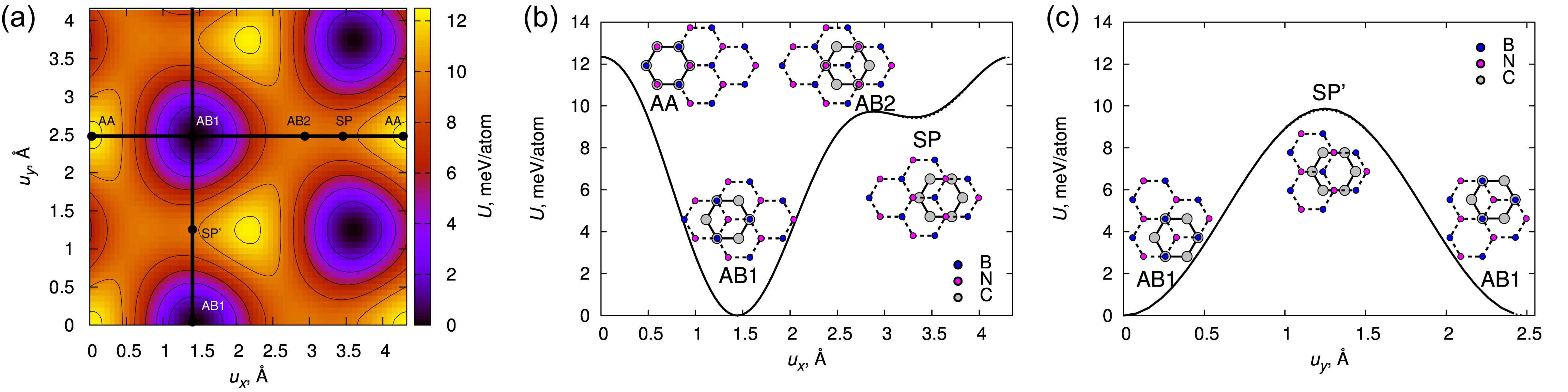
The calculations show that the lowest energy stacking for the commensurate unit cell of the graphene/boron-nitride heterostructure is AB1 in which boron atoms are located on top of carbon atoms and nitrogen atoms are on top of centers of hexagons, in agreement with previous findings Fan et al. (2011); Li et al. (2012); Giovannetti et al. (2007); Zhao et al. (2014); Leven et al. (2016); Zhou et al. (2015); Sachs et al. (2011); Argentero et al. (2017) (Fig. 1). For this stacking, the optimized lattice constant of the heterostructure is Å, close to the previously calculated values of 2.48–2.50 Å (Ref. Zhou et al., 2015). The lattice constants of single layers of graphene and hexagonal boron nitride optimized within the same computational approach are Å and Å (Ref. Lebedeva et al., 2016), respectively. Therefore, the graphene and boron nitride layers in the heterostructure are stretched and compressed by 0.86% and 0.91%, respectively. It should be also metioned that the calculated lattice constants for graphene and boron nitride are in agreement with the experimental data for graphite of 2.46140.0001 Å (Ref. Pease, 1952), 2.450.03 Å (Ref. Bernal, 1924), 2.45890.0005 Å (Ref. Baskin and Meyer, 1955), 2.46120.0001 Å (Ref. Ludsteck, 1972), 2.4640.002 Å (Ref. Trucano and Chen, 1975), 2.462 Å (Ref. Zhao and Spain, 1989) and 2.463 Å (Ref. Bosak et al., 2007) and boron nitride bulk of 2.50380.0001 Å (Ref. Pease, 1950), 2.503990.00005 Å (Ref. Pease, 1952), 2.5040.002 Å (Ref. Solozhenko et al., 2001, 1995), 2.5050.002 Å (Ref. Solozhenko and Peun, 1997), 2.5047 0.0002 Å (Ref. Paszkowicz et al., 2002), 2.506 Å (Ref. Bosak et al., 2006), 2.5240.020 Å (Ref. Yoo et al., 1997) and 2.50380.0003 Å (Ref. Yamamura et al., 1997).
The potential energy surface of the graphene/boron-nitride heterostructure calculated for the optimized commensurate unit cell (Fig. 1a) is in qualitative agreement with the previous studies Fan et al. (2011); Zhao et al. (2014); Leven et al. (2016); Zhou et al. (2015); Sachs et al. (2011); Argentero et al. (2017). Two types of maxima on the potential energy surface correspond to the AA and AB2 stackings (Fig. 1b). In the first of these stackings, all boron and nitrogen atoms are on top of carbon atoms and the energy of this stacking relative the ground-state AB1 stacking is 12.35 meV/atom, which is within the range of the values obtained at the optimized interlayer distance using different methods of 5.63 meV/atom (DFT-TS) Zhao et al. (2014), 5.4 meV/atom (vdW-DF2) Argentero et al. (2017), 10.86 meV/atom (HSE+MBD) Leven et al. (2016), 15.68 meV/atom (DFT-D2), 5.35 meV/atom (vdW-DF2), 9.92 meV/atom (RPA) Zhou et al. (2015) and 10.5 meV/atom (RPA) Sachs et al. (2011) (note that all energies in the present paper are given in meV per atom in the upper (adsorbed) layer). The second smaller maximum with the relative energy 9.73 meV/atom corresponds to the AB2 stacking in which nitrogen atoms are located on top of carbon atoms and boron atoms are on top of centers of hexagons. For comparison, the literature values for the relative energy of the AB2 stacking are 4.5 meV/atom (DFT-TS) Zhao et al. (2014), 4.6 meV/atom (vdW-DF2) Argentero et al. (2017), 12.96 meV/atom (DFT-D2), 4.68 meV/atom (vdW-DF2), 8.67 meV/atom (RPA) Zhou et al. (2015) and 9 meV/atom (RPA) Sachs et al. (2011).
The saddle point (SP) for the transition between adjacent energy minima (Fig. 1a) lies on the straight line in the armchair direction connecting the AA and AB2 stackings on the potential energy surface, 0.427 Å away from the AB2 stacking and 1.015 Å away from the AA stacking (Fig. 1b). The relative energy of this SP stacking corresponding to the barrier to relative in-plane motion of the graphene and boron nitride layers is 9.46 meV/atom, i.e. only 0.27 meV/atom smaller than the relative energy of the AB2 stacking. The previously reported values of the barrier obtained at the optimized interlayer distance include 3.9 meV/atom (DFT-TS) Zhao et al. (2014), 4.4 meV/atom (vdW-DF2) Argentero et al. (2017), 13 meV/atom (DFT-D2), 4.5 meV/atom (vdW-DF2) and 8.5 meV/atom (RPA) Zhou et al. (2015).
It should be noted that the calculated barrier for the graphene/boron-nitride heterostructure is several times greater than the barriers to relative sliding of two graphene layers or two boron nitride layers. The reported barriers to relative sliding of graphene layers range from 0.5 to 2.4 meV/atom (Refs. Kolmogorov and Crespi, 2005; Aoki and Amawashi, 2007; Ershova et al., 2010; Lebedeva et al., 2011a; Reguzzoni et al., 2012; Zhou et al., 2015; Lebedeva et al., 2016, 2017a). There are also estimates of this barrier from the experimental measurements of the shear mode frequency and width of dislocations in few-layer graphene of 1.7 meV/atom (Ref. Popov et al., 2012a) and 2.4 meV/atom (Ref. Alden et al., 2013), respectively. The published values of the barriers for boron nitride layers range from 2.3 meV/atom to 4.3 meV/atom (Refs. Constantinescu et al., 2013; Zhou et al., 2015; Lebedev et al., 2016; Lebedeva et al., 2017a). The same approach as used in the present paper gives the barriers for bilayer graphene and boron nitride of 1.6 meV/atom (Ref. Lebedeva et al., 2016, 2017a) and 3.9 meV/atom (Ref. Lebedev et al., 2016; Lebedeva et al., 2017a), respectively, i.e. six and two and a half times smaller than the value for the graphene/boron-nitride heterostructure.
The comparison of the relative energies of symmetric stackings for the graphene/boron-nitride heterostructure obtained here and in previous papers Zhao et al. (2014); Zhou et al. (2015); Sachs et al. (2011) shows that the approach applied in the present paper, i.e. the combination of the vdW-DF2 functional with the use of the experimental interlayer distance in DFT calculations, overestimates the characteristics of the potential surface of interlayer interaction energy by 10% – 20% with respect to more accurate RPA calculations Zhou et al. (2015); Sachs et al. (2011). This error can be partially attributed to the fixed interlayer distance in our study since according to the RPA calculations Zhou et al. (2015); Sachs et al. (2011), the optimal interlayer distance varies by 0.2 Å for different stackings. Nevertheless, this error is small compared, for example, to the scatter of the experimental data on the total binding energy of graphene layers Liu et al. (2012); Zacharia et al. (2004); Benedict et al. (1998); Girifalco and Lad (1956) or more than 50% deviation of the relative energies of symmetric stackings following from DFT calculations at the optimized interlayer distance Zhao et al. (2014); Zhou et al. (2015) from the RPA data. These observations are in agreement with the previous comparison of performance of different methods for pure graphene and boron nitride Lebedeva et al. (2017a). Therefore, the combination of the vdW-DF2 functional with the use of the experimental interlayer distance in standard DFT calculations is a computationally cheap but sufficiently accurate alternative to expensive methods, such as RPA.
III Approximation of potential energy surface
The possibility to accurately approximate potential energy surfaces by expressions containing only the first spatial Fourier harmonics determined by the system symmetry has been previously demonstrated for various types of interacting layers, including purely graphene Ershova et al. (2010); Lebedeva et al. (2011a); Popov et al. (2012a); Lebedeva et al. (2012); Zhou et al. (2015); Reguzzoni et al. (2012) and boron nitride Lebedev et al. (2016); Zhou et al. (2015) systems as well as carbon nanotube walls in the case when the walls are infinite and commensurate Belikov et al. (2004); Bichoutskaia et al. (2005, 2009); Popov et al. (2009, 2012b) and when the corrugations of the potential energy surface are determined by edges Popov et al. (2013) or defects Belikov et al. (2004). An expression for the potential surface of interaction energy of graphene and boron nitride layers including 5 fitting parameters has been also proposed Zhou et al. (2015). In the present paper we show that this potential energy surface can be approximated using only two independent fitting parameters. A similar approximation of the potential energy surface with the first spatial Fourier components has been used for studies of strain distribution and band gap opening in a graphene layer on the boron nitride crystal Jung et al. (2015); Kumar et al. (2015). However, the adequacy of this approximation has not been addressed.
We consider the graphene layer as adsorbed on the boron nitride one and use that the potential energy surface of an atom adsorbed on a 2D trigonal lattice can be approximated by the first Fourier harmonics as Verhoeven et al. (2004)
| (1) |
where and axes are chosen in the armchair and zigzag directions, respectively, , , is the lattice constant, describes the relative position of the atom with respect to the 2D lattice and point corresponds to the case when the atom is located on top of one of the lattice atoms. In the case of graphene/boron-nitride heterostructures, we should sum up interactions of carbon atoms with the boron (CB) and nitrogen (CN) lattices. Thus, we get
| (2) |
where describes the relative position of the graphene and boron nitride layers, point corresponds to the AA stacking and . It is seen that corrugations of the potential energy surface in flat graphene/boron-nitride heterostructures are described by two parameters and , which determine all physical properties related to the interlayer interaction, such as the barrier to relative sliding of the layers, shear modulus and shear mode frequency Popov et al. (2012a); Lebedeva et al. (2012); Lebedev et al. (2016); Lebedeva et al. (2016, 2017a).
The parameters of the approximation can be found from the relative energies of the symmetric stackings AA, AB1 and AB2 as
| (3) |
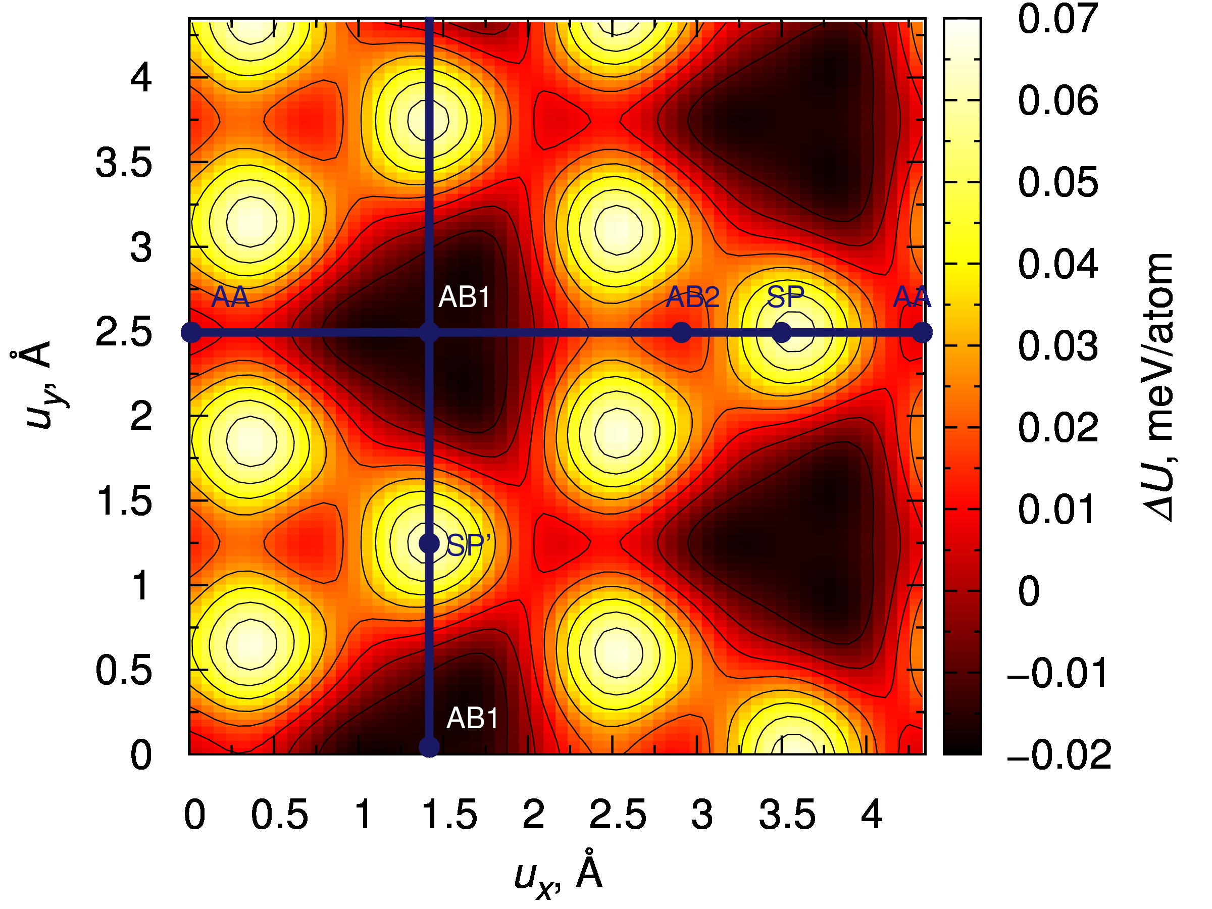
The values obtained are meV/atom and meV/atom. The greater value of compared to can be explained by the stronger repulsion between carbon atoms and negatively charged nitrogen ions compared to positively charged boron ions. The standard deviation of the approximated potential energy surface from the one obtained by the DFT calculations is only 0.0305 meV/atom (Fig. 1b,c and 2), which is within 0.25% of the energy difference between the AA and AB1 stackings. The largest deviations of the approximation from the DFT results of up to 0.07 meV/atom are observed for the regions around the saddle-point stacking SP (Fig. 2).
IV Properties of graphene/boron-nitride heterostructures
In this section we consider graphene/boron-nitride systems characterized by different stacking patterns and degree of incommensurability. Using the approach introduced by Porovskiĭ and Talapov in their pioneer paper Porovskiĭ and Talapov (1978) on the commensurate-incommensurate phase transition and used for description of such a transition in multilayer films on surfaces (see, for example, Ref. Chung et al., 1987) we distinguish the following states: (1) commensurate system in which the layers have the same lattice constant and are in the AB1 stacking corresponding to the minimal interlayer interaction energy, (2) slightly incommensurate system in which there is a small lattice mismatch of the layers leading to formation of large commensurate domains separated by narrow incommensurate boundaries corresponding to stacking dislocations, (3) highly incommensurate system in which there is a considerable mismatch in the lattice constants of the layers but the positions of atoms in the layers are perturbed by the interlayer interaction and (4) fully incommensurate system in which there is a considerable mismatch in the lattice constants of the layers and the interlayer interaction virturally does not disturb the positions of atoms in the layers.
The ground state of the graphene/boron-nitride bilayer with the aligned layers is the highly incommensurate system (3) with the period of the Moiré pattern comparable to the width of boundaries between commensurate domains Woods et al. (2014); Argentero et al. (2017); Tang et al. (2013); Yang et al. (2013). The relative rotation of the graphene and boron nitride layers leads to the transition to state (4), in which the potential energy surface is extremely smooth and no deformations of the layers due to the interlayer interactions are observed Woods et al. (2014). A commensurate system (1) can be realized for a flake on a large substrate layer when the flake size is smaller than the period of the Moiré pattern or in the case when the graphene layer is stretched so that its lattice constant reaches the one for boron nitride. Biaxial stretching is required for bilayer geometry, while uniaxial stretching is sufficient for a ribbon of the width smaller than the period of the Moiré pattern on a wide substrate layer or on another ribbon. A slightly incommensurate system (2) can be achieved in this case when the lattice constant of graphene is slightly different from the one for boron nitride.
Our model of the interlayer interaction energy described by Eq. 2 does not take into account changes in the interlayer distance and thus we limit our consideration to the case of flat systems. The experimental measurements gave the height variation for supported graphene/boron-nitride systems of about 0.4 Å (Ref. Yang et al., 2013). This is comparable to the 0.2 Å variation of the optimal interlayer distance for different stackings according to the RPA calculations Zhou et al. (2015); Sachs et al. (2011). Therefore, the deviation of 10% – 20% for the relative energies of symmetric stackings obtained here at the fixed interlayer distance from the RPA data Zhou et al. (2015); Sachs et al. (2011) for the variable interlayer distance (see section II) provides an estimate of the accuracy of our model for supported graphene/boron-nitride bilayers. The variation in the interlayer distance should be also insignificant for commensurate or fully incommensurate systems. On the other hand, very strong surface corrugation with the characteristic amplitude of 8 Å was predicted for free-standing graphene/boron-nitride bilayers on the basis of atomistic simulations Argentero et al. (2017); Leven et al. (2016). To be able to describe quantitatively the properties of such corrugated structures the model should be supplemented by the terms describing the dependence of the interlayer interaction energy on the interlayer distance similar to approximations of the potential energy surface proposed for graphene/boron-nitride heterostructures Zhou et al. (2015); Jung et al. (2015) and graphene bilayer Reguzzoni et al. (2012) and interlayer atomic potentials Kolmogorov and Crespi (2005); Lebedeva et al. (2011a) for graphene. Nevertheless, even in the present form the model can still provide a qualitative insight into the phenomena coming from the interlayer interaction and serve as an important step towards development of more complicated models with account of variations in the interlayer distance.
The possibility to describe the potential energy surface of graphene/boron-nitride heterostructures with only two independent parameters within Eq. 2 means that a large number of properties of such systems are interrelated and expressed through these two parameters, similar to the cases of pure graphene and boron nitride systems Popov et al. (2012a); Lebedev et al. (2016); Lebedeva et al. (2011a). Below we estimate the following physical properties of systems of different incommensurability. First the barrier to relative rotation of graphene and boron nitride layers, which corresponds to the transition from state (1) to state (4), is obtained for commensurate flakes on a large substrate layer. The shear mode frequencies are evaluated for various commensurate systems (1). The period of the Moiré pattern is analyzed for the highly incommensurate state (3) corresponding to the ground state of the graphene/boron-nitride bilayer with the aligned layers. The phase transition from the commensurate state (1) to the slightly incommensurate state (2) with a low density of stacking dislocations and characteristics of these dislocations are studied in the last part of this section.
IV.1 Barrier to rotation
We start consideration of physical properties of graphene/boron-nitride systems from the barrier to relative rotation of the layers from the commensurate state. As mentioned above, though the ground state of the graphene/boron-nitride bilayer is incommensurate and it is difficult to realize the rotation in macroscopic systems, such a rotation is relevant for commensurate flakes on a large substrate layer. From studies for graphene it is known that superlubric behavior Dienwiebel et al. (2004, 2005); Filippov et al. (2008); Xu et al. (2013) and diffusion Lebedeva et al. (2010, 2011b) of flakes on a periodic substrate occurs via rotation, which brings the system to the fully incommensurate state Woods et al. (2014) with an extremely smooth potential energy surface. Correspondingly, the diffusion coefficient of flakes is determined by the barrier to rotation from the commensurate state to the fully incommensurate one Lebedeva et al. (2010, 2011b). The potential energy of the latter can be found as the average interlayer interaction energy given by Eq. 2
| (4) |
Therefore, the barrier to relative rotation of the graphene and boron nitride layers from the commensurate state with the AB1 stacking can be estimated as meV/atom. This value is in agreement with the estimate of the relative energy of the fully incommensurate state from the RPA calculationsSachs et al. (2011) of 7 meV/atom and is somewhat greater than the reported barriers to relative rotation of two graphene layers of 5 meV/atom (Ref. Popov et al., 2012a) and 4 meV/atom (Ref. Lebedeva et al., 2010, 2011b) and of two boron nitride layers of 6.3 meV/atom (Ref. Lebedev et al., 2016).
IV.2 Shear mode frequency
One of the experimentally measurable quantities that can be used to probe the potential surface of interlayer interaction energy is the frequency of the shear mode in which commensurate layers rigidly slide with respect to each other parallel to the planeLebedeva et al. (2011a, 2012); Popov et al. (2012a); Lebedev et al. (2016); Lebedeva et al. (2017a). To estimate shear mode frequencies for commensurate systems of the graphene/boron-nitride bilayer, a graphene flake on a boron nitride layer and a boron nitride flake on a graphene layer the calculations of the curvature of the potential energy surface around the AB1 minimum are performed for the commensurate unit cells with different lattice constants corresponding to the optimized lattice constants of the bilayer and single graphene and boron nitride layers. The graphene and boron nitride layers are rigidly displaced within 0.05 Å in the armchair direction and the obtained energy curves are approximated by parabolas.
The calculations show that the curvatures of the potential energy surface for the lattice constants and corresponding to the isolated boron nitride and graphene layers differ only by 1.9% and 2.6%, respectively, from the value for the lattice constant of the bilayer. The curvature of the potential energy surface for the bilayer can be also estimated from Eq. 2 as eV/Å. This estimate is only 1.3% greater than the value obtained directly from the DFT calculations.
The shear mode frequencies are then found as Popov et al. (2012a); Lebedev et al. (2016); Lebedeva et al. (2017a)
| (5) |
Here for the graphene flake on the boron nitride layer , for the boron nitride flake on the graphene layer and for the bilayer , where , and are masses of carbon, boron and nitrogen atoms, respectively. The shear mode frequencies calculated in this way are listed in Table 1. As seen from this table, the results for the graphene flake on the boron nitride layer and the boron nitride flake on the graphene layer are virtually indistinguishable due to the close reduced masses and curvatures of the potential energy surface.
It should be also noted that the estimated shear mode frequency for the graphene/boron-nitride bilayer of 37 cm-1 is somewhat higher than the frequencies for bilayer graphene Lebedeva et al. (2017a) of 29 cm-1 and boron nitride Lebedev et al. (2016); Lebedeva et al. (2017a) of 34 cm-1 obtained within the same computational approach. This value is also greater than the results of experimental measurements for bilayer graphene of 28 3 cm-1 (Ref. Boschetto et al., 2013) and 32 cm-1 (Ref. Tan et al., 2012).
| structure | (Å) | (cm-1) |
|---|---|---|
| graphene flake/boron nitride | 2.5207 | 26.59 |
| bilayer | 2.4978 | 36.95 |
| boron nitride flake/graphene | 2.4767 | 25.58 |
IV.3 Moiré pattern
Let us now obtain the correction to the period of the Moiré pattern in the incommensurate ground state of graphene/boron-nitride heterostructures induced by the interlayer interaction. First we consider the relationship between the elastic and interlayer interaction energies in the fully incommensurate and commensurate states of the aligned graphene and boron nitride layers. Maintaining the structure of the layers the same as in the absence of the interlayer interaction is related to excess in the average density of the interlayer interaction energy compared to the commensurate state of mJ/m2, where Å2 is the area per one carbon atom. Transformation of the incommensurate structure to the commensurate one with the uniformly stretched graphene layer and compressed boron nitride layer, on the other hand, is associated with the penalty in the elastic energy of , where % is the relative lattice mismatch, is the reduced elastic constant of the layers and is the Poisson ratio. In the present paper we use the values of the elastic constants of graphene and boron nitride layers J/m2 and J/m2 calculated previouslyLebedeva et al. (2016) using the same computational approach. Although slightly different values of the Poisson ratio were obtained for graphene and boron nitride, and , in this section we assume that the Poisson ratios of the layers are close and approximately equal to that for graphene (in section IV D the difference in the Poisson ratios of the graphene and boron nitride layers is taken into account). In the case when both of the graphene and boron nitride layers are free to relax in the plane (this can be achieved by using an incommensurate substrate such as a rotated graphene or boron nitride layer), the reduced elastic constant is J/m2 and the density of the elastic energy in the commensurate state mJ/m2. Comparison of energies and suggests that in the ground state the heterostructure should be incommensurate. For a free graphene layer on the boron nitride crystal (similar to the experimental studies Woods et al. (2014); Tang et al. (2013); Yang et al. (2013)), the interface boron nitride layer can be considered as nearly rigid Sachs et al. (2011); van Wijk et al. (2014). In this case the reduced elastic constant of the layers is approximately twice greater, the density of the elastic energy in the commensurate state is mJ/m2 and the incommensurate state is even more preferred. The same behavior with mJ/m2 should also be observed for a free boron nitride layer on the fixed graphite substrate.
Incommensurability of the graphene/boron-nitride systems is manifested through the formation of Moiré superstructures Woods et al. (2014); Argentero et al. (2017); Tang et al. (2013); Yang et al. (2013). In the case when the change in the bond lengths of the layers due to the interlayer interaction is neglected and the layers are completely aligned we can estimate that the period of the Moiré pattern is nm, in agreement with the experimental measurements of 14 nm Woods et al. (2014); Tang et al. (2013) and nm Yang et al. (2013) and the values of 14.1 nm (Ref. Leven et al., 2016) and 13.6 nm (Ref. van Wijk et al., 2014) observed in atomistic simulations. A similar estimate of 14 nm can be also obtained using typical values of the lattice constants of 2.461 Å and 2.504 Å from the experimental data for graphite Pease (1952); Baskin and Meyer (1955); Ludsteck (1972); Trucano and Chen (1975); Zhao and Spain (1989); Bosak et al. (2007) and boron nitride Paszkowicz et al. (2002); Yamamura et al. (1997); Pease (1950); Bosak et al. (2006); Solozhenko and Peun (1997); Solozhenko et al. (2001, 1995); Pease (1952). Nevertheless, since the characteristic interlayer interlayer interaction energy is comparable to the characteristic elastic energy , significant modulation of positions of atoms in the interacting layers is possible. Such a modulation has been previously observed in atomistic simulations van Wijk et al. (2014); Leven et al. (2016); Argentero et al. (2017) and calculations using continuum models Jung et al. (2015); Kumar et al. (2015). However, the correction to the period of the Moiré pattern induced by the interlayer interaction has not been considered explicitly. Below we quantify this correction for aligned graphene and boron nitride layers.
In heterostructures formed by uniformly deformed graphene and boron nitride layers (with the constant in-plane strains) the relative displacement of atoms in the layers varies uniformly with the absolute position of atoms within the layers , , where is the period of the Moiré pattern, axes and are chosen in the armchair and zigzag directions and the point , corresponds to the AA stacking following the notations from sections II and III. The Moiré pattern has the same hexagonal symmetry as the potential energy surface, which is imposed by the geometry of the layers, with the only difference that the unit cell of the Moiré pattern is scaled by a factor of as compared to the unit cell of the potential energy surface. Obviously this symmetry is not changed by the interlayer interaction. However, the interlayer interaction modifies the period of the Moiré pattern and the relative displacement of atoms in the layers . Here we assume that the perturbations and are small so that and . Since the symmetry of the pattern is not affected by the interlayer interaction, the correction to the relative displacement of atoms should vanish at the symmetry planes. This is automatically satisfied for the correction of the form
| (6) |
i.e. in the case when the correction is proportional to the force of interlayer interaction.
The interlayer interaction energy can then be expanded as
| (7) |
It is sufficient to stop here at the first-order terms in as it can be easily checked that the second-order terms vanish upon the integration over the unit cell of the Moiré superstructure and do not contribute to the total energy. Integrating Eq. 7 over the unit cell of the Moiré superstructure, we get the average interlayer interaction energy per unit area
| (8) |
where
| (9) |
and this parameter corresponds to the characteristic corrugation of the potential energy surface.
Tensile () and shear () strains associated with the corrections to the period of the Moiré pattern and relative displacement of the layers are given by
| (10) |
Using notation for the total strain
| (11) |
the elastic energy of the heterostructure can be written as
| (12) |
The average elastic energy per unit area is therefore given by
| (13) |
The total energy of the heterostructure relative to the incommensurate state with no in-plane deformation of the layers due to the interlayer interaction is minimal for
| (14) |
Let us now check that the resulting correction to the relative displacement of atoms in the layers is actually much smaller than the lattice constant and thus the perturbation approach applied here is valid. From Eqs. 6 and 14 and relation it can be estimated that the characteristic magnitude of the correction to the relative displacement of atoms of the graphene and boron nitride layers is
| (15) |
This means that the approach used here makes sense as long as the characteristic magnitude of corrugation of the potential energy surface is less or comparable to the characteristic elastic energy . In our case mJ/m2, mJ/m2 when both of the graphene and boron nitride layers are free to relax in the plane, 103 mJ/m2 for the graphene layer on the fixed boron nitride substrate and 85 mJ/m2 for the boron nitride layer on the fixed graphite substrate, which ensures and adequacy of the approach used.
One of the consequences of the perturbation approach used is that in the limit of the strain in each free layer does not depend on whether the second layer is free or fixed. This is clear from Eq. 14 as the coefficient , which determines the relative displacement of atoms in the layers, is inversely proportional to the reduced elastic constant of the system. In the case when both of the layers are free to relax in the plane, absolute displacements of atoms in the graphene and boron nitride layers correspond to the fractions and of the relative displacement , respectively. As a result, the same displacement as on the fixed substrate with or , respectively, is obtained.
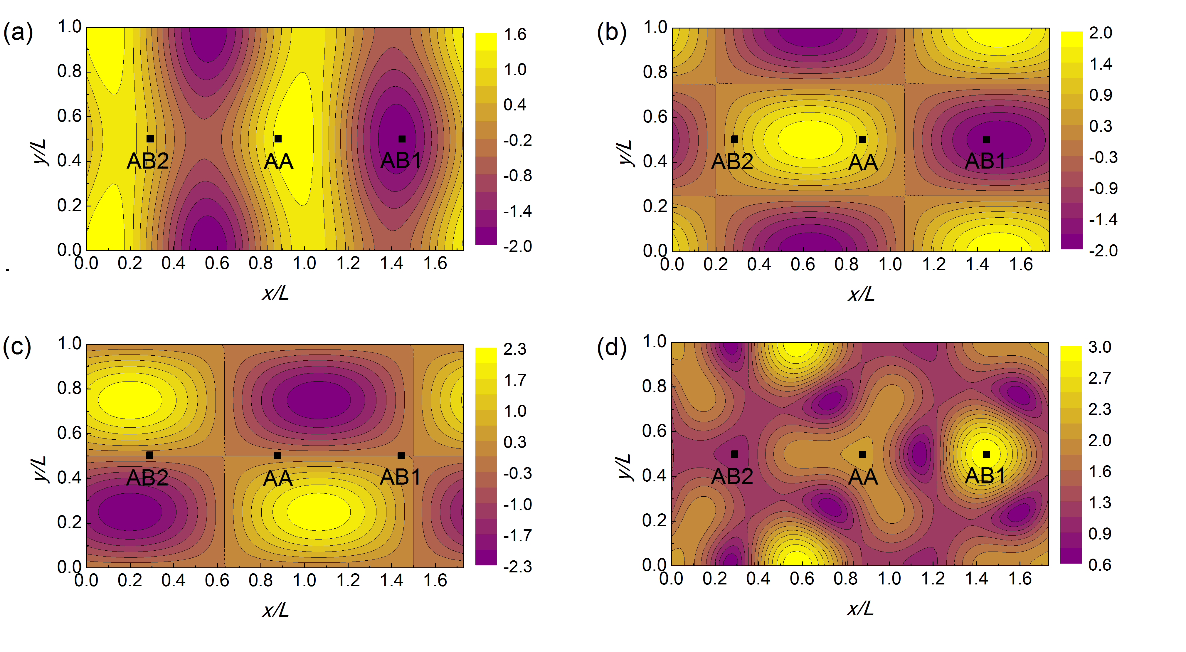
The distribution patterns of strain in free layers for are shown in Fig. 3 in units of for the graphene layer and for the boron nitride layer. Such a strain distribution is qualitatively similar to the distribution of bond lengths observed in atomistic simulations van Wijk et al. (2014); Leven et al. (2016); Argentero et al. (2017) and elastic energy maps obtained within continuum models Jung et al. (2015); Kumar et al. (2015). As can be expected, the maximal strains of about are observed in the regions with the AB1 stacking, where the layers tend to be commensurate in order to minimize the interlayer interaction energy (Fig. 3). These maximal strains of 0.6 – 0.7% are in agreement with variations of the bond length of about 1% measured experimentally for the graphene layer on the boron nitride crystal Woods et al. (2014). The minimal strains of about are achieved for the stacking that is intermediate between the AA and AB1 stackings. Adjusting the period of the Moiré superstructure allows to reduce the strain though the term (see Eq. 10).
With account of Eq. 14, the energy of the heterostructure relative to the incommensurate state with no in-plane deformation of the layers due to the interlayer interaction takes the form
| (16) |
The optimal change of the period of the Moiré superstructure is then roughly
| (17) |
When one of the graphene or boron nitride layers is fixed, the correction to the period of the Moiré superstructure is rather small. For the fixed graphene layer, nm, i.e. 2.3% of the period of the Moiré superstructure without account of in-plane deformation of the layers due to the interlayer interaction. For the fixed boron nitride layer, nm, i.e. 1.5% of . In the latter case, the estimated period of the Moiré superstructure is nm. The same as , this is close to the experimentally measured period of the Moiré superstructure for the aligned graphene layer on the boron nitride crystal of about 14 nm Woods et al. (2014); Tang et al. (2013) and nm Yang et al. (2013). However, these experimental data are insufficient to confirm the effect of the interlayer interaction. A more significant correction to the period of the Moiré superstructure of nm, i.e. 9.2% of , with the resulting period of nm, is expected when both of the graphene and boron nitride layers are free to relax in the plane, which can be the case for the graphene/boron-nitride bilayer on an incommensurate substrate, for example, on a rotated layer of graphene or boron nitride. Experimental measurements for such a system could help to distinguish the effect of the interlayer interaction.
IV.4 Stacking dislocations in slightly incommensurate systems
Let us now consider stacking dislocations in slightly incommensurate graphene/boron-nitride systems. Stretching graphene so that its lattice constant increases up to the one for boron nitride results in formation of the commensurate structure with the minimal interlayer interaction energy. Futher stretching or compressing the graphene layer should lead to a competition in the elastic energy of the free boron nitride layer and interlayer interaction energy resolved through the transition to the slightly incommesurate state with stacking dislocations. In other words, a commensurate-incommensurate phase transition Porovskiĭ and Talapov (1978) should take place at some critical strain associated with the difference in the average lattice constants of the graphene and boron nitride layers.
As discussed in the beginning of section IV, a slightly incommensurate system can be realized by biaxial stretching of the graphene layer for bilayer geometry or by uniaxial stretching if the boron nitride layer is a ribbon of the width smaller than the period of the Moiré superstructure. In the latter case stretching should take place along the ribbon axis and we disregard the effect of the ribbon edges on the potential surface of interlayer interaction energy, which is reasonable if the ribbon width is much greater than the lattice constant and the edges are properly terminated, e.g. by hydrogen. We also assume that the density of stacking dislocations is low so that the interaction between the dislocations can be neglected. These assumptions allow us to use the formalism of the two-chain Frenkel-Kontorova model Bichoutskaia et al. (2006), in which two layers are represented as chains of particles connected by harmonic springs and coupled by van der Waals interactions. The model has been already applied to study the commensurate-incommensurate phase transition in double-walled carbon nanotubes Bichoutskaia et al. (2006); Popov et al. (2009), bilayer graphene Popov et al. (2011); Lebedeva et al. (2016) and boron nitride Lebedev et al. (2016); Lebedeva et al. (2016) as well as edge stacking dislocations in bilayer graphene Lebedeva et al. (2017b).
Following the approach from papers Popov et al. (2011); Lebedeva et al. (2016); Lebedev et al. (2016), it is first necessary to choose the adequate approximation of the dislocation path, i.e. the curve on the potential energy surface described by the dependence of relative displacement of the layers on the coordinate in the direction perpendicular to the boundary between commensurate domains that minimizes the formation energy of dislocations. In the case of graphene/boron-nitride heterostructures, the minimum energy path between the AB1 minima passing through the SP stacking only slightly deviates from the straight line between adjacent energy minima in the zigzag direction. The barrier along this straight path (corresponding to the SP’ stacking) is 9.81 meV/atom (Fig. 1c). This is only 4% higher than the barrier along the minimum energy path through the SP stacking and within the accuracy of the DFT calculations with corrections for van der Waals interactions. The SP’ stacking is obtained from the SP stacking by shifting the layers by only 0.29 Å. Therefore, it can be safely assumed that the dislocation path in graphene/boron-nitride heterostructures lies along the straight line between adjacent energy minima AB1.
On the basis of Eq. 2, the relative potential energy along the straight dislocation path is then approximated as
| (18) |
where , is the relative displacement of the layers along the dislocation path, which changes from 0 to the magnitude of the Burgers vector , and is the barrier per unit area. The barrier along this path calculated from Eq. 2 is meV/atom, which is exactly equal to our DFT value. The variation of the barrier due to changes in the lattice constant from to lies within 2% and is neglected. Therefore, we estimate the barrier per unit area as J/m2.
The dislocation width depends on the angle between the Burgers vector and the normal to the boundary between commensurate domains Lebedev et al. (2016); Lebedeva et al. (2016) and is given by
| (19) |
where describes the dependence of the reduced elastic constant of the layers on fractions of tensile and shear character in the dislocation, and are the reduced tensile and shear elastic constants. When the boron nitride and graphene layers are of similar width, both of the layers participate in the formation of the dislocation and the reduced constants are given by and , where and , respectively. For the boron nitride ribbon on the wide graphene layer, the dislocation appears only in the boron nitride layer and, correspondingly, and .
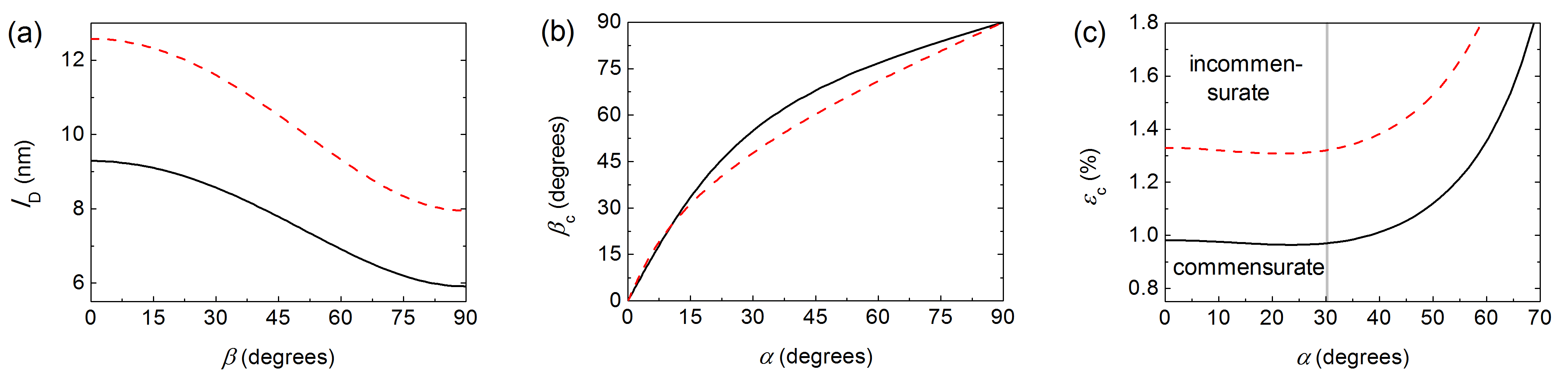
As seen from Fig. 4a, the dislocation width decreases with increasing the angle , i.e. changing the dislocation character from tensile to shear. The estimated dislocation widths in the case of similar widths of the graphene and boron nitride layers are 6 – 9 nm, which is much smaller then the width of full dislocations in bilayer boron nitride of 12 – 16 nm (Ref. Lebedev et al., 2016; Lebedeva et al., 2016) evaluated within the same approach and only a little smaller than the corresponding results for partial dislocations in bilayer graphene of 8 – 14 nm (Ref. Popov et al., 2011; Lebedeva et al., 2016). These values also lie within the range of experimental data on dislocation widths in bilayer graphene of 6 – 11 nm (Ref. Alden et al., 2013; Lin et al., 2013; Yankowitz et al., 2014). While the barrier along the dislocation path in graphene/boron-nitride heterostructures is several times greater than that in bilayer graphene, the length of this path is also greater (the dislocation path length is equal to the lattice constant in the heterostructure and to the bond length in bilayer graphene) and the resulting dislocation widths are close.
The dislocation energy , i.e. the energy of the state with one stacking dislocation relative to the commensurate state with equal lattice constants of the layers per unit length of the boundary between commensurate domains, follows the same dependence on the angle as the dislocation width (Refs. Lebedev et al., 2016; Lebedeva et al., 2016). For the system of two layers of similar width this energy ranges from 0.42 meV/Å for tensile dilsocations to 0.27 meV/Å for shear dislocations, which is about four times greater than for bilayer graphene Popov et al. (2011); Lebedeva et al. (2016) and comparable to the estimates for bilayer boron nitride Lebedev et al. (2016); Lebedeva et al. (2016). For the boron nitride ribbon on the wide graphene layer, the corresponding values are 0.57 meV/Å and 0.36 meV/Å, respectively.
Let us now consider the commensurate-incommensurate phase transition in the system in which the average lattice constant of graphene in one of the directions (along the ribbon axis in the case of the boron nitride layer of the ribbon shape) is slightly smaller or larger than the average lattice constant of boron nitride. The commensurate phase should be observed for strains in the graphene layer within the interval , where is the critical strain associated with the average lattice mismatch of the graphene and boron nitride layers at which the formation energy of stacking dislocations goes to zero. The commensurate-incommensurate phase transition in similar systems of pure graphene and boron nitride with the uniaxially stretched substrate layer was considered in our previous paper Lebedeva et al. (2016). In that paper we derived the expressions for and the optimal angle between the boundary separating commensurate domains and the Burgers vector which minimizes the formation energy of stacking dislocations at the critical strain (or at any strain in the substrate layer if the free layer is a ribbon). According to these derivations, the optimal angle between the boundary separating commensurate domains and the Burgers vector depends on the angle between the Burgers vector and the direction in which the average lattice constants of the layers are slightly different (Fig. 4b) as
| (20) |
In the case of the graphene/boron-nitride systems the critical strain associated with the average lattice mismatch between the graphene and boron nitride layers Lebedeva et al. (2016) is given by
| (21) |
while the absolute critical strain in the graphene layer takes the values of .
As seen from Fig. 4c, the critical strain for is about 0.98% when the layers are of similar width and 1.33% for the boron nitride ribbon on the wide graphene layer. The dependence of the critical strain on the angle is rather weak for angles within . A shallow minimum in the critical strain of about 0.96% is reached at for the layers of similar width. For the boron nitride ribbon on the wide graphene layer, the minimal is about 1.31% and is reached at . With increasing beyond the critical strain grows fast and tends to infinity at . Such a behavior is explained by the fact that the formation energy of stacking dislocations cannot be reduced by stretching the substrate layer in the direction perpendicular to the Burgers vector.
As the Burgers vector is aligned along one of the zigzag directions, for a given geometry of the system, only six orientations of the Burgers vector are possible. Among these six types of possible dislocations, the dislocations with the angle , where is the smallest angle between one of the zigzag directions and the direction in which the average lattice constants of the graphene and boron nitride layers are slightly different, are characterized by the lowest critical strain and should appear first upon changing the lattice constant of the graphene layer relative to the boron nitride layer. Therefore, corresponds to the critical strain associated with the average lattice mismatch of the layers at which the commensurate-incommensurate phase transition takes place in graphene/boron-nitride heterostructures (Fig. 4c). It should be mentioned that this critical strain for the layers of similar width is only slightly greater than the corresponding value for bilayer boron nitride of 0.75% and almost three times greater than the critical strain for formation of the first dislocation in bilayer graphene of about 0.36% (Ref. Lebedeva et al., 2016).
V Conclusions and discussion
The potential energy surface of commensurate graphene and boron nitride layers has been calculated within the DFT approach based on the vdW-DF2 functional Lee et al. (2010). It is shown that such an approach combined with the use of the experimental interlayer distance provides reliable characteristics of the potential energy surface that are in agreement with more accurate but much more expensive computational methods, such as RPA. The calculated barrier to relative motion of graphene and boron nitride layers of 9.5 meV/atom is several times greater than the values for two graphene or boron nitride layers.
It has been checked that the approximation of the calculated potential energy surface by the first spatial Fourier components, an approach which is widely used in literature Zhou et al. (2015); Jung et al. (2015); Kumar et al. (2015) to analyze electronic properties, is highly accurate. Such an approximation allows to describe the potential energy surface of flat graphene/boron-nitride heterostructures using only two independent parameters. This means that a large number of physical properties of graphene/boron-nitride systems are interrelated and are expressed through these two parameters as well. In the present paper we have used the approximation of the potential energy surface to estimate the shear mode frequency in the commensurate state, the barrier to relative rotation of graphene and boron nitride layers from the commensurate state to the fully incommensurate one, the width of stacking dislocations in slightly incommensurate systems and the period of the Moiré superstructure of the highly incommensurate ground state of the graphene/boron-nitride bilayer.
It is shown that the interlayer interaction in the highly incommensurate ground state of the graphene/boron-nitride systems with the layers aligned leads to modulation of atomic positions in the layers, which results in the increase of the period of Moiré superstructure by 9% in the case of free graphene and boron nitride layers on an incommensurate substrate and about 2% in the case when one of the layers is fixed. The maximal strains in the graphene and boron nitride layers are on the order of 0.6 – 0.7%, in agreement with the experimental observations Woods et al. (2014).
Commensurate or slightly incommensurate graphene/boron-nitride systems can be realized by stretching the graphene layer or restricting the system geometry to flakes of the size smaller than the period of the Moiré superstructure. The shear mode frequencies for the commensurate graphene/boron-nitride heterostructure, a graphene flake on a boron nitride layer and a boron nitride flake on a graphene layer have been calculated. The estimated barrier to relative rotation of the layers from the commesurate to fully incommensurate state of 7.4 meV/atom is comparable to the previously reported values for pure graphene or boron nitride systems.
The characteristrics of stacking dislocations have been studied for slightly incommensurate systems of boron nitride and graphene layers of similar width with the biaxially stretched graphene layer or a boron nitride ribbon of the width smaller than the period of the Moiré superstructure on a wide graphene layer stretched along the ribbon axis. The estimated dislocation widths for these two types of systems lie in the ranges of 6 – 9 nm and 8 – 13 nm, respectively, where the lower bound corresponds to shear dislocations and the higher one to tensile dislocations. It is suggested that changing the lattice constant of graphene with respect to boron nitride in one of the directions (in the system with the boron nitride ribbon along the ribbon axis) should result in observation of the commensurate-incommensurate phase transition. The estimated strain intervals for the graphene layer corresponding to the commensurate phase are about 0.8 – 2.7% in the case when the graphene and boron nitride layers are of similar width and 0.4 – 3.1% for the boron nitride ribbon on the wide graphene layer.
Let us now discuss the possibility of experimental measurements of the calculated properties related to the interaction of graphene and boron nitride layers. The estimated barrier to relative rotation of the layers is relevant for dynamics of flakes on periodic substrates, i.e. for such processes as superlubricity Dienwiebel et al. (2004, 2005); Filippov et al. (2008); Xu et al. (2013) and diffusion Lebedeva et al. (2010, 2011b). In the latter case the diffusion coefficient of flakes is exponentially dependent on this barrier Lebedeva et al. (2010, 2011b). The shear mode frequency in bilayers can be measured by Raman scattering Tan et al. (2012) and coherent phonon spectroscopy Boschetto et al. (2013), as demonstrated for graphene Tan et al. (2012); Boschetto et al. (2013). The transmission electron microscopy Alden et al. (2013); Lin et al. (2013) and scanning tunneling microscopy Yankowitz et al. (2014) allow direct measurements of the dislocation width by analogy with papers Alden et al. (2013); Lin et al. (2013); Yankowitz et al. (2014) on graphene. The experiments for heterostructures with the stretched graphene layer should make it possible to observe the commesurate-incommensurate phase transition. The period of the Moiré pattern for graphene on boron nitride crystal has been already determined by scanning tunneling microscopy and atomic force measurements Woods et al. (2014); Tang et al. (2013); Yang et al. (2013). The consideration of flat heterostructures with both free layers, which can be realized in the case of an incommensurate substrate, such as a rotated graphene or boron nitride layer, would allow to distinguish the change in the period of the Moiré pattern coming from the interlayer interaction. Such studies could provide a valuable experimental insight into the graphene/boron-nitride interlayer interaction due to the link between these properties and the potential energy surface established in the present paper.
Acknowledgements.
AL and AP acknowledge the Russian Foundation of Basic Research (16-52-00181) and computational time on the Multipurpose Computing Complex NRC “Kurchatov Institute”. IL acknowledges the financial support from Grupos Consolidados UPV/EHU del Gobierno Vasco (IT578-13) and EU-H2020 project “MOSTOPHOS” (n. 646259).References
- Geim and Grigorieva (2013) A. K. Geim and I. V. Grigorieva, Nature 499, 419 (2013).
- Novoselov and Castro Neto (2012) K. S. Novoselov and A. H. Castro Neto, Physica Scripta 2012, 014006 (2012).
- Dean et al. (2010) C. R. Dean, A. F. Young, I. Meric, C. Lee, L. Wang, S. Sorgenfrei, K. Watanabe, T. Taniguchi, P. Kim, K. L. Shepard, and J. Hone, Nature Nanotechnology 5, 722 (2010).
- Xue et al. (2011) J. Xue, J. Sanchez-Yamagishi, D. Bulmash, P. Jacquod, A. Deshpande, K. Watanabe, T. Taniguchi, P. Jarillo-Herrero, and B. J. LeRoy, Nat. Mater. 10, 282 (2011).
- Zomer et al. (2011) P. J. Zomer, S. P. Dash, N. Tombros, and B. J. van Wees, Applied Physics Letters 99, 232104 (2011).
- Decker et al. (2011) R. Decker, Y. Wang, V. W. Brar, W. Regan, H.-Z. Tsai, Q. Wu, W. Gannett, A. Zettl, and M. F. Crommie, Nano Lett. 11, 2291 (2011).
- Dean et al. (2012) C. Dean, A. F. Young, L. Wang, I. Meric, G.-H. Lee, K. Watanabe, T. Taniguchi, K. Shepard, P. Kim, and J. Hone, Solid State Communications 152, 1275 (2012).
- Ponomarenko et al. (2011) L. A. Ponomarenko, A. K. Geim, A. A. Zhukov, R. Jalil, S. V. Morozov, K. S. Novoselov, I. V. Grigorieva, E. H. Hill, V. V. Cheianov, V. I. Fal’ko, K. Watanabe, T. Taniguchi, and R. V. Gorbachev, Nature Phys. 7, 958 (2011).
- Kim et al. (2011) E. Kim, T. Yu, E. S. Song, and B. Yu, Applied Physics Letters 98, 262103 (2011).
- Jain et al. (2013) N. Jain, T. Bansal, C. A. Durcan, Y. Xu, and B. Yu, Carbon 54, 396 (2013).
- Lee et al. (2011) G.-H. Lee, Y.-J. Yu, C. Lee, C. Dean, K. L. Shepard, P. Kim, and J. Hone, Applied Physics Letters 99, 243114 (2011).
- Britnell et al. (2012a) L. Britnell, R. V. Gorbachev, R. Jalil, B. D. Belle, F. Schedin, M. I. Katsnelson, L. Eaves, S. V. Morozov, A. S. Mayorov, N. M. R. Peres, A. H. Castro Neto, J. Leist, A. K. Geim, L. A. Ponomarenko, and K. S. Novoselov, Nano Lett. 12, 1707 (2012a).
- Britnell et al. (2012b) L. Britnell, R. V. Gorbachev, R. Jalil, B. D. Belle, F. Schedin, A. Mishchenko, T. Georgiou, M. I. Katsnelson, L. Eaves, S. V. Morozov, N. M. R. Peres, J. Leist, A. K. Geim, K. S. Novoselov, and L. A. Ponomarenko, Science 335, 947 (2012b).
- Özçelik and Ciraci (2013) V. O. Özçelik and S. Ciraci, The Journal of Physical Chemistry C 117, 15327 (2013).
- Shi et al. (2014) G. Shi, Y. Hanlumyuang, Z. Liu, Y. Gong, W. Gao, B. Li, J. Kono, J. Lou, R. Vajtai, P. Sharma, and P. M. Ajayan, Nano Letters 14, 1739 (2014).
- Li et al. (2012) Y.-J. Li, Q.-Q. Sun, L. Chen, P. Zhou, P.-F. Wang, S.-J. Ding, and D. W. Zhang, AIP Advances 2, 012191 (2012).
- Gorbachev et al. (2012) R. V. Gorbachev, A. K. Geim, M. I. Katsnelson, K. S. Novoselov, T. Tudorovskiy, I. V. Grigorieva, A. H. MacDonald, S. V. Morozov, K. Watanabe, T. Taniguchi, and L. A. Ponomarenko, Nature Physics 8, 896 (2012).
- Perali et al. (2013) A. Perali, D. Neilson, and A. R. Hamilton, Phys. Rev. Lett. 110, 146803 (2013).
- Woods et al. (2014) C. R. Woods, L. Britnell, A. Eckmann, R. S. Ma, J. C. Lu, H. M. Guo, X. Lin, G. L. Yu, Y. Cao, R. V. Gorbachev, A. V. Kretinin, J. Park, L. A. Ponomarenko, M. I. Katsnelson, Y. N. Gornostyrev, K. Watanabe, T. Taniguchi, C. Casiraghi, H.-J. Gao, A. K. Geim, and K. S. Novoselov, Nature Physics 10, 451 (2014).
- Tang et al. (2013) S. Tang, H. Wang, Y. Zhang, A. Li, H. Xie, X. Liu, L. Liu, T. Li, F. Huang, X. Xie, and M. Jiang, Scientific Reports 3, 2666 (2013).
- Yang et al. (2013) W. Yang, G. Chen, Z. Shi, C.-C. Liu, L. Zhang, G. Xie, M. Cheng, D. Wang, R. Yang, D. Shi, K. Watanabe, T. Taniguchi, Y. Yao, Y. Zhang, and G. Zhang, Nature Materials 12, 792 (2013).
- Yankowitz et al. (2012) M. Yankowitz, J. Xue, D. Cormode, J. D. Sanchez-Yamagishi, K. Watanabe, T. Taniguchi, P. Jarillo-Herrero, P. Jacquod, and B. J. LeRoy, Nature Physics 8, 382 (2012).
- Dean et al. (2013) C. R. Dean, L. Wang, P. Maher, C. Forsythe, F. Ghahari, Y. Gao, J. Katoch, M. Ishigami, P. Moon, M. Koshino, T. Taniguchi, K. Watanabe, K. L. Shepard, J. Hone, and P. Kim, Nature 497, 598 (2013).
- Hunt et al. (2013) B. Hunt, J. D. Sanchez-Yamagishi, A. F. Young, M. Yankowitz, B. J. LeRoy, K. Watanabe, T. Taniguchi, P. Moon, M. Koshino, P. Jarillo-Herrero, and R. C. Ashoori, Science 340, 1427 (2013).
- Ponomarenko et al. (2013) L. A. Ponomarenko, R. V. Gorbachev, G. L. Yu, D. C. Elias, R. Jalil, A. A. Patel, A. Mishchenko, A. S. Mayorov, C. R. Woods, J. R. Wallbank, M. Mucha-Kruczynski, B. A. Piot, M. Potemski, I. V. Grigorieva, K. S. Novoselov, F. Guinea, V. I. Fal’ko, and A. K. Geim, Nature 497, 594 (2013).
- Chen et al. (2014) Z.-G. Chen, Z. Shi, W. Yang, X. Lu, Y. Lai, H. Yan, F. Wang, G. Zhang, and Z. Li, Nature Communications 5, 4461 (2014).
- Mucha-Kruczyński et al. (2016) M. Mucha-Kruczyński, J. R. Wallbank, and V. I. Fal’ko, Phys. Rev. B 93, 085409 (2016).
- Kumar et al. (2015) H. Kumar, D. Er, L. Dong, J. Li, and V. B. Shenoy, Scientific Reports 5, 10872 (2015).
- Slotman et al. (2015) G. J. Slotman, M. M. van Wijk, P.-L. Zhao, A. Fasolino, M. I. Katsnelson, and S. Yuan, Phys. Rev. Lett. 115, 186801 (2015).
- Eckmann et al. (2013) A. Eckmann, J. Park, H. Yang, D. Elias, A. S. Mayorov, G. Yu, R. Jalil, K. S. Novoselov, R. V. Gorbachev, M. Lazzeri, A. K. Geim, and C. Casiraghi, Nano Lett. 13, 5242 (2013).
- Jung et al. (2015) J. Jung, A. M. DaSilva, A. H. MacDonald, and S. Adam, Nature Communications 6, 6308 (2015).
- Sachs et al. (2011) B. Sachs, T. O. Wehling, M. I. Katsnelson, and A. I. Lichtenstein, Phys. Rev. B 84, 195414 (2011).
- Argentero et al. (2017) G. Argentero, A. Mittelberger, M. R. A. Monazam, Y. Cao, T. J. Pennycook, C. Mangler, C. Kramberger, J. Kotakoski, A. K. Geim, and J. C. Meyer, Nano Lett. 17, 1409 (2017).
- Woods et al. (2016) C. R. Woods, F. Withers, M. J. Zhu, Y. Cao, G. Yu, A. Kozikov, M. Ben Shalom, S. V. Morozov, M. M. van Wijk, A. Fasolino, M. I. Katsnelson, K. Watanabe, T. Taniguchi, A. K. Geim, A. Mishchenko, and K. S. Novoselov, Nature Communications 7, 10800 (2016).
- Leven et al. (2013) I. Leven, D. Krepel, O. Shemesh, and O. Hod, J. Phys. Chem. Lett. 4, 115 (2013).
- Fan et al. (2011) Y. Fan, M. Zhao, Z. Wang, X. Zhang, and H. Zhang, Applied Physics Letters 98, 083103 (2011).
- Giovannetti et al. (2007) G. Giovannetti, P. A. Khomyakov, G. Brocks, P. J. Kelly, and J. van den Brink, Phys. Rev. B 76, 073103 (2007).
- Leven et al. (2016) I. Leven, T. Maaravi, I. Azuri, L. Kronik, and O. Hod, J. Chem. Theor. Comp. 12, 2896 (2016).
- Zhao et al. (2014) X. Zhao, L. Li, and M. Zhao, J. Phys. Condens. Matter 26, 095002 (2014).
- Zhou et al. (2015) S. Zhou, J. Han, S. Dai, J. Sun, and D. J. Srolovitz, Phys. Rev. B 92, 155438 (2015).
- Lebedeva et al. (2011a) I. V. Lebedeva, A. A. Knizhnik, A. M. Popov, Y. E. Lozovik, and B. V. Potapkin, Phys. Chem. Chem. Phys. 13, 5687 (2011a).
- Reguzzoni et al. (2012) M. Reguzzoni, A. Fasolino, E. Molinari, and M. C. Righi, Phys. Rev. B 86, 245434 (2012).
- Lee et al. (2010) K. Lee, E. D. Murray, L. Kong, B. I. Lundqvist, and D. C. Langreth, Phys. Rev. B 82, 081101 (2010).
- van Wijk et al. (2014) M. M. van Wijk, A. Schuring, M. I. Katsnelson, and A. Fasolino, Phys. Rev. Lett. 113, 135504 (2014).
- Neek-Amal and Peeters (2014) M. Neek-Amal and F. M. Peeters, Applied Physics Letters 104, 041909 (2014).
- Popov et al. (2012a) A. M. Popov, I. V. Lebedeva, A. A. Knizhnik, Y. E. Lozovik, and B. V. Potapkin, Chem. Phys. Lett. 536, 82 (2012a).
- Lebedev et al. (2016) A. V. Lebedev, I. V. Lebedeva, A. A. Knizhnik, and A. M. Popov, RSC Advances 6, 6423 (2016).
- Kresse and Furthmüller (1996) G. Kresse and J. Furthmüller, Phys. Rev. B 54, 11169 (1996).
- Kresse and Joubert (1999) G. Kresse and D. Joubert, Phys. Rev. B 59, 1758 (1999).
- Monkhorst and Pack (1976) H. J. Monkhorst and J. D. Pack, Phys. Rev. B 13, 5188 (1976).
- Pease (1950) R. S. Pease, Nature 165, 722 (1950).
- Pease (1952) R. S. Pease, Acta Crystallographica 5, 356 (1952).
- Lynch and Drickamer (1966) R. W. Lynch and H. G. Drickamer, J. Chem. Phys. 44, 181 (1966).
- Solozhenko et al. (1995) V. L. Solozhenko, G. Will, and F. Elf, Solid State Communications 96, 1 (1995).
- Solozhenko and Peun (1997) V. L. Solozhenko and T. Peun, J. Phys. Chem. Solids 58, 1321 (1997).
- Solozhenko et al. (2001) V. L. Solozhenko, A. G. Lazarenko, J.-P. Petitet, and A. V. Kanaev, J. Phys. Chem. Solids 62, 1331 (2001).
- Paszkowicz et al. (2002) W. Paszkowicz, J. B. Pelka, M. Knapp, T. Szyszko, and S. Podsiadlo, Appl. Phys. A 75, 431 (2002).
- Bosak et al. (2006) A. Bosak, J. Serrano, M. Krisch, K. Watanabe, T. Taniguchi, and H. Kanda, Phys. Rev. B 73, 041402 (2006).
- Fuchizaki et al. (2008) K. Fuchizaki, T. Nakamichi, H. Saitoh, and Y. Katayama, Solid State Communications 148, 390 (2008).
- Bernal (1924) J. D. Bernal, Proc. R. Soc. London, Ser. A 106, 749 (1924).
- Baskin and Meyer (1955) V. Baskin and L. Meyer, Phys. Rev. 100, 544 (1955).
- Ludsteck (1972) V. A. Ludsteck, Acta Crystallographica, Section A 28, 59 (1972).
- Trucano and Chen (1975) P. Trucano and R. Chen, Nature 258, 136 (1975).
- Zhao and Spain (1989) Y. X. Zhao and I. L. Spain, Phys. Rev. B 40, 993 (1989).
- Bosak et al. (2007) A. Bosak, M. Krisch, M. Mohr, J. Maultzsch, and C. Thomsen, Phys. Rev. B 75, 153408 (2007).
- Lebedeva et al. (2017a) I. V. Lebedeva, A. V. Lebedev, A. M. Popov, and A. A. Knizhnik, Computational Materials Science 128, 45 (2017a).
- Lebedeva et al. (2016) I. V. Lebedeva, A. V. Lebedev, A. M. Popov, and A. A. Knizhnik, Phys. Rev. B 93, 235414 (2016).
- Yoo et al. (1997) C. S. Yoo, J. Akella, H. Cynn, and M. Nicol, Phys. Rev. B 56, 140 (1997).
- Yamamura et al. (1997) S. Yamamura, M. Takata, and M. Sakata, Journal of Physics and Chemistry of Solids 58, 177 (1997).
- Kolmogorov and Crespi (2005) A. N. Kolmogorov and V. H. Crespi, Phys. Rev. B 71, 235415 (2005).
- Aoki and Amawashi (2007) M. Aoki and H. Amawashi, Solid State Communications 142, 123 (2007).
- Ershova et al. (2010) O. V. Ershova, T. C. Lillestolen, and E. Bichoutskaia, Phys. Chem. Chem. Phys. 12, 6483 (2010).
- Alden et al. (2013) J. S. Alden, A. W. Tsen, P. Y. Huang, R. Hovden, L. Brown, J. Park, D. A. Muller, and P. L. McEuen, PNAS 110, 11256 (2013).
- Constantinescu et al. (2013) G. Constantinescu, A. Kuc, and T. Heine, Phys. Rev. Lett. 111, 036104 (2013).
- Liu et al. (2012) Z. Liu, J. Z. Liu, Y. Cheng, Z. Li, L. Wang, and Q. Zheng, Phys. Rev. B 85, 205418 (2012).
- Zacharia et al. (2004) R. Zacharia, H. Ulbricht, and T. Hertel, Phys. Rev. B 69, 155406 (2004).
- Benedict et al. (1998) L. X. Benedict, N. G. Chopra, M. L. Cohen, A. Zettl, S. G. Louie, and V. H. Crespi, Chem. Phys. Lett. 286, 490 (1998).
- Girifalco and Lad (1956) L. A. Girifalco and R. A. Lad, J. Chem. Phys. 25, 693 (1956).
- Lebedeva et al. (2012) I. V. Lebedeva, A. A. Knizhnik, A. M. Popov, Y. E. Lozovik, and B. V. Potapkin, Physica E 44, 949 (2012).
- Belikov et al. (2004) A. V. Belikov, Y. E. Lozovik, A. G. Nikolaev, and A. M. Popov, Chem. Phys. Lett. 385, 72 (2004).
- Bichoutskaia et al. (2005) E. Bichoutskaia, A. M. Popov, A. El-Barbary, M. I. Heggie, and Y. E. Lozovik, Phys. Rev. B 71, 113403 (2005).
- Bichoutskaia et al. (2009) E. Bichoutskaia, A. M. Popov, Y. E. Lozovik, O. V. Ershova, I. V. Lebedeva, and A. A. Knizhnik, Phys. Rev. B 80, 165427 (2009).
- Popov et al. (2009) A. M. Popov, Y. E. Lozovik, A. S. Sobennikov, and A. A. Knizhnik, JETP 108, 621 (2009).
- Popov et al. (2012b) A. M. Popov, I. V. Lebedeva, and A. A. Knizhnik, Appl. Phys. Lett. 100, 173101 (2012b).
- Popov et al. (2013) A. M. Popov, I. V. Lebedeva, A. A. Knizhnik, Y. E. Lozovik, and B. V. Potapkin, J. Chem. Phys. 138, 024703 (2013).
- Verhoeven et al. (2004) G. S. Verhoeven, M. Dienwiebel, and J. W. M. Frenken, Phys. Rev. B 70, 165418 (2004).
- Porovskiĭ and Talapov (1978) V. L. Porovskiĭ and A. L. Talapov, Soviet Physics JETP 48, 579 (1978).
- Chung et al. (1987) S. Chung, A. Kara, J. Z. Larese, W. Y. Leung, and D. R. Frankl, Phys. Rev. B 35, 4870 (1987).
- Dienwiebel et al. (2004) M. Dienwiebel, G. S. Verhoeven, N. Pradeep, J. W. M. Frenken, J. A. Heimberg, and H. W. Zandbergen, Phys. Rev. Lett. 92, 126101 (2004).
- Dienwiebel et al. (2005) M. Dienwiebel, N. Pradeep, G. S. Verhoeven, H. W. Zandbergen, and J. W. Frenken, Surf. Sci. 576, 197 (2005).
- Filippov et al. (2008) A. E. Filippov, M. Dienwiebel, J. W. M. Frenken, J. Klafter, and M. Urbakh, Phys. Rev. Lett. 100, 046102 (2008).
- Xu et al. (2013) Z. Xu, X. Li, B. I. Yakobson, and F. Ding, Nanoscale 5, 6736 (2013).
- Lebedeva et al. (2010) I. V. Lebedeva, A. A. Knizhnik, A. M. Popov, O. V. Ershova, Y. E. Lozovik, and B. V. Potapkin, Phys. Rev. B 82, 155460 (2010).
- Lebedeva et al. (2011b) I. V. Lebedeva, A. A. Knizhnik, A. M. Popov, O. V. Ershova, Y. E. Lozovik, and B. V. Potapkin, J. Chem. Phys. 134, 104505 (2011b).
- Boschetto et al. (2013) D. Boschetto, L. Malard, C. H. Lui, K. F. Mak, Z. Li, H. Yan, and T. F. Heinz, Nano Lett. 13, 4620 (2013).
- Tan et al. (2012) P. H. Tan, W. P. Han, W. J. Zhao, Z. H. Wu, K. Chang, H. Wang, Y. F. Wang, N. Bonini, N. Marzari, N. Pugno, G. Savini, A. Lombardo, and A. C. Ferrari, Nat. Mater. 11, 294 (2012).
- Bichoutskaia et al. (2006) E. Bichoutskaia, M. I. Heggie, Y. E. Lozovik, and A. M. Popov, Fullerenes, Nanotubes, Carbon Nanostruct. 14, 131 (2006).
- Popov et al. (2011) A. M. Popov, I. V. Lebedeva, A. A. Knizhnik, Y. E. Lozovik, and B. V. Potapkin, Phys. Rev. B 84, 045404 (2011).
- Lebedeva et al. (2017b) I. V. Lebedeva, A. A. Knizhnik, and A. M. Popov, Physica E: Low-dimensional Systems and Nanostructures 90, 49 (2017b).
- Lin et al. (2013) J. Lin, W. Fang, W. Zhou, A. R. Lupini, J. C. Idrobo, J. Kong, S. J. Pennycook, and S. T. Pantelides, Nano Letters 13, 3262 (2013).
- Yankowitz et al. (2014) M. Yankowitz, J. I.-J. Wang, A. G. Birdwell, Y.-A. Chen, K. Watanabe, T. Taniguchi, P. Jacquod, P. San-Jose, P. Jarillo-Herrero, and B. J. LeRoy, Nat. Mater. 13, 786 (2014).