Optical circulation in a multimode optomechanical resonator
Abstract
Optical circulators are important components of modern day communication technology. With their ability to route photons directionally, these nonreciprocal elements provide useful functionality in photonic circuits and offer prospects for fundamental research on information processing. Developing highly efficient optical circulators thus presents an important challenge, in particular to realize compact reconfigurable implementations that do not rely on a magnetic field bias to break reciprocity. We demonstrate optical circulation based on radiation pressure interactions in an on-chip multimode optomechanical system. We show that mechanically-mediated optical mode conversion in a silica microtoroid provides a synthetic gauge bias for light, which enables a 4-port circulator by exploiting tailored interference between appropriate light paths. We identify two sideband conditions under which ideal circulation is approached. This allows to experimentally demonstrate 10 dB isolation and 3 dB insertion loss in all relevant channels. We show the possibility of actively controlling the bandwidth, isolation ratio, noise performance and circulation direction, enabling ideal opportunities for reconfigurable integrated nanophotonic circuits.
Introduction
Optical circulators route photons in a unidirectional fashion among different ports, with diverse applications in advanced communication systems, including dense wavelength division multiplexing and bi-directional sensors and amplifiers. Their operation offers opportunities for routing quantum information Sliwa2015 ; Scheucher2016 and to realize photonic states whose propagation in a lattice is topologically protected Lu2014 ; Roushan2017 . Traditionally, nonreciprocal elements such as circulators and isolators have relied on applied magnetic bias fields to break time-reversal symmetry and Lorentz reciprocity. While significant progress has been made towards introducing magneto-optic materials in photonic circuits Shoji2014 , realizing low-loss, linear, efficient, and compact photonic circulators on a chip remains an outstanding challenge. In recent years, coupled-mode systems that create an effective magnetic field using parametric modulations have been recognized as powerful alternatives Fang2012 ; Poulton2012 ; Estep2014 ; Sliwa2015 ; Kim2015 ; Kerckhoff2015 ; Ranzani2015 ; Metelmann2015 . Optomechanical systems, where multiple optical and mechanical modes are coupled through radiation pressure Aspelmeyer2014 ; Hill2012 ; Andrews2014 , provide an effective platform to realize such modulation Hafezi2012 ; Xu2015 ; Miri2017 . Nonreciprocal transmission and optical isolation were demonstrated in several optomechanical implementations, including ring resonators, photonic crystal nanobeams, and superconducting circuits Shen2016 ; Ruesink2016 ; Fang2017 ; Peterson2017 ; Bernier2016 . Recently, nonreciprocal circulation for microwave signals was reported in a superconducting device exhibiting directional frequency conversion Barzanjeh2017 . Here, by leveraging a synthetic gauge field created in a multimode optomechanical system, we realize a compact and highly reconfigurable on-chip circulator in the photonic (telecommunication) domain. The working principle, relying on tailored interfering paths, allows for operation at equal-frequency input and output fields and could be applied in a wide variety of platforms. We reveal the importance of control fields to regulate the nonreciprocal response and identify two distinct regimes, with and without employing optomechanical gain, where this response can approach ideal circulation.
Results
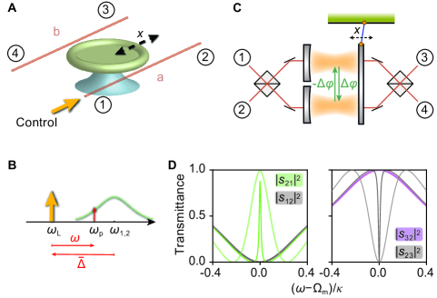
Our experimental system consists of a high-Q microtoroid resonator Armani2003 that is simultaneously coupled to two tapered optical fibres, forming four ports through which light can enter and exit (Fig. 1A). The microtoroid supports nearly degenerate odd and even optical modes — superpositions of clockwise and counterclockwise propagating waves — coupled through a mechanical breathing mode, to form a three-mode optomechanical system. A control beam incident through port 1 populates both modes, labelled by , with intracavity control fields that exhibit phase difference Yu2009 . When detuned from the cavity, these control fields induce linear couplings between the mechanical resonator and both cavity modes at rates , where is the vacuum optomechanical coupling rate Aspelmeyer2014 . For red-detuned control (Fig. 1B), photon transfer from mode 1 to mode 2 via the mechanical resonator then takes place at rate , with the mechanical linewidth. In contrast, transfer from mode 21 occurs at rate , i.e., with opposite phase. The control field thus biases the mode-conversion process with maximally nonreciprocal phase Ruesink2016 ; Miri2017 . This phase is reminiscent of a synthetic d.c. magnetic flux that breaks time-reversal symmetry Fang2012a and can, under appropriate conditions, serve to create an optical circulator.
Our system is fully equivalent to the general Fabry-Pérot model sketched in Fig. 1C, where the beamsplitters impart a phase shift on reflections from either side. From each port the two cavities are then excited with the same phase difference as the even and odd modes in the ring resonator. In absence of optomechanical coupling this realizes a reciprocal ‘add-drop’ filter: off-resonant light propagates from port 1(3) to port 2(4) and vice versa, while resonant light is routed from 1(2) to 4(3). However, in the presence of a control beam at a frequency detuned from the cavity frequencies by , with the mechanical resonance frequency, a weaker probe beam at frequency (Fig. 1B) experiences an optomechanically induced transparency (OMIT Weis2010 ) window when : the probe is routed from port 1 to 2 rather than ‘dropped’ in port 4. This behaviour is quantified in Fig. 1D, which shows scattering matrix elements , signalling transmission from port to , for two control powers. These are obtained from a rigorous coupled-mode model describing the optomechanical three-mode system (Materials and Methods). The response is clearly nonreciprocal: the OMIT window for (green curves, left panel) does not occur for probe light incident from port 2 (grey), which remains dropped in port 3 (purple, right panel). Likewise, light from port 3 is suppressed (grey) and routed to port 4, etc. The optomechanical interactions in this multimode system thus allow nonreciprocal add-drop functionality, which can also be related to momentum-matching of intracavity control and probe fields Hafezi2012 . For proper bias conditions this yields a circulator, i.e., a control beam incident from port 1 or 3 allows probe transmission 12, 23, 34, 41, whereas a control from port 2 or 4 reverses the circulation direction.
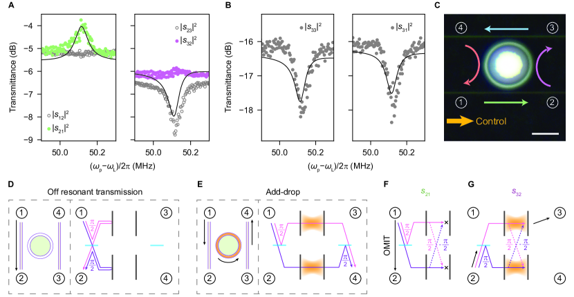
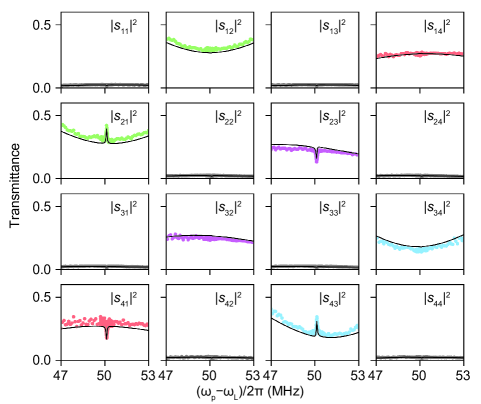
In experiment, we measure circulation using a heterodyne technique (Materials and Methods) to obtain transmission spectra for all 16 port combinations that constitute the scattering matrix. The studied microtoroid has nearly degenerate optical modes at with intrinsic loss rate , and supports a mechanical breathing mode at (). The two optical modes are assumed to have equal total loss rates , where are exchange losses to waveguides a and b. Figure 2A shows the measured probe transmittances in the direct (12) and add-drop (23) channels when the control is detuned to the lower mechanical sideband of the cavity (). OMIT is observed in the copropagating direct channel (), accompanied by reduced transmission in the add-drop channel (). The OMIT features are absent in reverse operation of the device, which thus exhibits nonreciprocal transport. The overall effect is optical circulation in the direction 12341 (see Supplementary Materials for all 16 scattering matrix elements).
To understand the role of mechanically-mediated mode transfer in the observed response, we recapitulate the operation of conventional add-drop filters: when a probe signal from port 1(3) does not excite the two modes (e.g. because it is off-resonance), it interferes constructively in port 2(4) and vice versa (Fig. 2D). When the probe does excite both modes, their phase difference means that light constructively interferes in the drop port (e.g. 14, Fig. 2E). However, a control beam reconfigures this behaviour through nonreciprocal mode conversion. Now a probe signal incident from port 1 reaches each mode either directly or via the parametric mode conversion process. As a result of the phase shift associated with the mode-transfer paths, the direct and mode-transfer path destructively interfere in both cavities (Fig. 2F). Consequently, a probe from port 1 does not excite the modes and is transmitted to port 2 instead of 4. In contrast, a probe from port 2 excites both modes with opposite phase difference, such that interference inside the cavities is constructive and light is routed to port 3 (Fig. 2G). Therefore, circulation can only occur in a properly configured two-mode optical system. In particular, the presence of a direct scattering path between ports 1 and 2 (and 34) is crucial to induce the appropriate phase shift and interference causing circulation.
The strength of the optomechanical interactions between the optical modes and the mechanical resonance is tuned by the control laser power and can be parametrised by the cooperativities . Perfect optical circulation, with infinite isolation and zero insertion loss, is approached at high cooperativities and vanishing intrinsic loss (Fig. 1D). Stronger nonreciprocity is thus obtained for larger optomechanical coupling than currently achieved in our experiment (Fig. 2, limited by thermal instabilities), which reached (obtained from a global fit of the 44 transmittance matrix, see Supplementary Materials). Moreover, the isolation could be increased by increasing the normalized coupling rates such that the exchange losses to the waveguides overcome the intrinsic cavity losses (, MHz in Fig. 2).
Generally, the performance of add-drop filters is limited by a finite mode splitting , which in ring resonators results from surface inhomogeneities that directly couple clockwise and counterclockwise propagating waves Kippenberg2002 . This changes the relative phase with which both (odd and even) modes are excited, leading to small () reflection () and cross-coupling () signals in our circulator (Fig. 2B) indicative of a normalized mode splitting . Interestingly, the optomechanical interaction suppresses these unwanted signals over the nonreciprocal frequency band (Fig. 2B). Assuming equal control powers in the optical modes () the resonantly reflected signal at port of waveguide a,b reads (see Supplementary Materials). A large cooperativity thus annihilates unwanted reflection (and likewise cross-coupling). This can be understood by recognizing that the nonreciprocal mode coupling at rate then dominates the direct optical coupling , making the impact of the latter on optical response negligible.
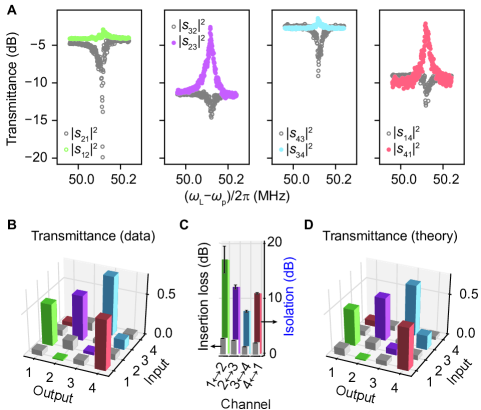
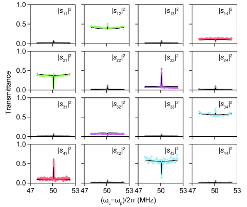
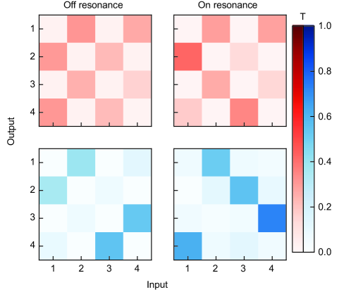
One way to overcome the limitation on isolation due to intrinsic loss is to introduce gain. This naturally occurs in our system when the control beam is detuned to the blue mechanical sideband () Aspelmeyer2014 . In this regime, the device still acts as a circulator, but with opposite handedness , since the mode conversion process for blue-detuned control fields has opposite phase, i.e., . As a result, constructive and destructive intracavity interference happen opposite to the scenarios depicted in Figs. 2F-G. Now, a probe signal co-propagating with the control beam experiences optomechanically induced absorption. Figure 3A plots the probe transmittances for the direct and add-drop channels for . We indeed observe a reduction of co-propagating probe signal due to induced absorption (grey data points). Moreover, and resulting from mode splitting, counter-propagating signals (colored data points) experience OMIT, which significantly enhances the nonreciprocal system response. This response is characterised by inspecting the complete 44 transmittance matrix (for ) shown in Fig. 3B. Besides displaying a clear asymmetry, we use this matrix to calculate the per-channel isolation ( or more) and insertion loss () as displayed in Fig. 3C. The properties of the realized circulator agree well with the prediction of our model for a cooperativity of (Fig. 3D). Importantly, our theory predicts (Supplementary Materials) that loss and gain can be balanced to give complete blocking(transmittance) in unwanted(preferred) directions. For this condition reads , resulting in a nonreciprocal bandwidth and finite backreflections , which can be relatively small in an undercoupled scenario.
Discussion
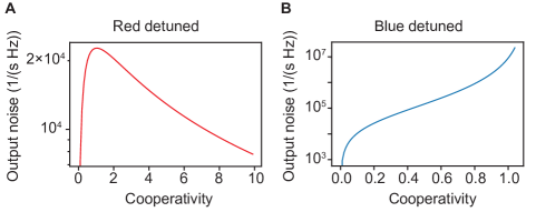
In addition to the transport properties, the noise performance of the circulator is important for faithful signal processing, especially for applications in the quantum domain. Assuming equal control powers in both modes, the added noise at port due to thermal occupation of the mechanical mode can be written at resonance as and , where the upper(lower) sign corresponds to a red(blue) detuned control respectively. Interestingly, the noise added to the ports is independent of the direction of circulation and ports 1 and 3 have noise contribution only in the presence of split optical modes . Active control over thus presents the possibility to steer noise, choosing to protect either source or receiver. For degenerate modes, the thermal bath adds less than 1 photon () in the optical ports when , showing that it is beneficial to use high-frequency mechanical resonators exhibiting smaller thermal populations. Moreover, this regime is more easily met for a red-detuned control, where an increased cooperativity widens the OMIT peak Weis2010 and distributes the noise over a larger bandwidth. In contrast, a blue-detuned control deteriorates this bandwidth and thus requires more stringent conditions on . As such, to achieve strong circulation at small control power, blue detuning can be beneficial, whereas to maximize bandwidth and noise performance, the red-detuned regime is preferred. It would be good to ascertain whether schemes that include more optical or mechanical modes would allow increased flexibility to mitigate noise and improve bandwidth.
In conclusion, we demonstrated nonreciprocal circulation of light through radiation pressure interactions in a three-mode system, with active reconfigurability regulated via the strength, phase and detuning of control fields. Our experiments and theoretical model recognize different regimes of circulating response and reveal the general importance of destructive intracavity interference between direct and mode-conversion paths on the device properties. These principles can lead to useful functionality for signal processing and optical routing in compact, on-chip photonic devices.
Materials and Methods
Experimental details
The microtoroid is fabricated using previously reported techniques, see e.g. Armani2003 .
The sample is placed in a vacuum chamber operated at mbar and room temperature.
Two tapered optical fibres, mounted on translation stages, are positioned near the toroid to couple the waveguides and optical modes.
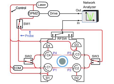
Three electronically controlled 12 optical switches (SW) are used in tandem to launch the probe beam into one of the four ports.
A schematic of the experimental set-up is provided in the Supplementary Materials.
A tunable laser (New Focus, TLB-6728) at is locked to one of the mechanical sidebands of the cavity mode, with a Pound-Drever-Hall scheme, and launched in port 1.
The output of a vector network analyser (VNA, R&S ZNB8) at frequency drives a Double-Parallel Mach-Zehnder Interferometer (DPMZI, Thorlabs LN86S-FC) to generate the probe beam at frequency .
The DPMZI is operated in a single-sideband suppressed-carrier mode, allowing selection of the relevant sideband at frequency or .
The power and polarisation of the control and probe beams are controlled by variable optical attenuators and fibre polarisation controllers respectively.
The probe beam exiting a port is combined with the control beam on a fast, low-noise photo detector whose output is analysed by the VNA.
All four detectors are connected to the VNA through a 41 radio frequency switch (RFSW).
Scattering matrix for the optomechanical circulator
Considering an optomechanical system that consists of two optical modes coupled to one mechanical mode, the modal amplitudes of the intracavity probe photons () and the phonon annihilation operator are governed by the following coupled dynamical equations Aspelmeyer2014 :
| (1) | ||||
| (2) |
In these relations, the loss rate of each optical mode is defined as , where refers to the intrinsic optical loss rate of the mode, and , are the exchange losses to waveguides a and b. The -matrix elements specify the coupling between input fields , incident from port , and the optical modes. In addition, and respectively represent the enhanced optomechanical coupling and the modified frequency detunings, where is the frequency detuning of the control laser with respect to the optical resonance frequencies. Here, we consider a frequency splitting of between the resonance frequencies of the two optical modes, and without loss of generality assume thus . Equations (1,2) completely describe the behaviour of the system in connection with the input-output relations:
| (3) |
where the matrix defines the port-to-port direct path scattering matrix of the optical circuit, while and its transpose describe the mode-to-port and port-to-mode coupling processes respectively. Using the rotating wave approximation, equations (1 - 3) lead to the frequency-domain scattering matrix:
| (4) |
Here the upper and lower signs correspond to a control laser that is red- () and blue-detuned () with respect to the optical resonance. In addition, and respectively represent the inverse mechanical and optical susceptibilities, where . Note that , the mechanically-mediated mode conversion rate, is identified from the off-diagonal elements of the matrix.
The direct-path scattering matrix for the side-coupled geometry that describes both systems in Fig. 1A and Fig. 1C is
| (5) |
The matrix is obtained from symmetry considerations, power conservation () and time reversal symmetry () Suh2004 . For the even and odd mode picture, the matrix reads
| (6) |
Equation 4, combined with eqs. 5 and 6 fully specifies the scattering matrix of our 4-port circulator. We assume equal losses () and equal control powers () in the two optical modes to fit the experimentally measured transmittances () using a global fitting procedure (see Supplementary Materials).
Supplementary Materials
Section S1. Experimental setup
Section S2. Measurement and fitting procedure for the transmittance matrix
Section S3. Conditions for near-ideal circulation
Section S4. Parametric instability threshold
Section S5. Circulation bandwidth
Section S6. Thermal noise
Fig. S1. Experimental setup
Fig. S2. Data for red detuned control with fits
Fig. S3. Data for blue detuned control with fits
Fig. S4. Asymmetric transmittance matrices
Fig. S5. Optimal circulation
Fig. S6. Added noise photons
References and Notes
- (1) K. M. Sliwa, M. Hatridge, A. Narla, S. Shankar, L. Frunzio, R. J. Schoelkopf, M. H. Devoret, Reconfigurable Josephson circulator/directional amplifier. Phys. Rev. X 5, 041020 (2015).
- (2) M. Scheucher, A. Hilico, E. Will, J. Volz, A. Rauschenbeutel, Quantum optical circulator controlled by a single chirally coupled atom. Science 354, 1577–1580 (2016).
- (3) L. Lu, J. D. Joannopoulos, M. Soljačić, Topological photonics. Nat. Photon. 8, 821–829 (2014).
- (4) P. Roushan, C. Neill, A. Megrant, Y. Chen, R. Babbush, R. Barends, B. Campbell, Z. Chen, B. Chiaro, A. Dunsworth, A. Fowler, E. Jeffrey, J. Kelly, E. Lucero, J. Mutus, P. J. J. O’Malley, M. Neeley, C. Quintana, D. Sank, A. Vainsencher, J. Wenner, T. White, E. Kapit, H. Neven, J. Martinis, Chiral ground-state currents of interacting photons in a synthetic magnetic field. Nat. Phys. 13, 146–151 (2017).
- (5) Y. Shoji, T. Mizumoto, Magneto-optical non-reciprocal devices in silicon photonics. Sci. Technol. Adv. Mater. 15, 014602 (2014).
- (6) K. Fang, Z. Yu, S. Fan, Realizing effective magnetic field for photons by controlling the phase of dynamic modulation. Nat. Photonics 6, 782–787 (2012).
- (7) C. G. Poulton, R. Pant, A. Byrnes, S. Fan, M. J. Steel, B. J. Eggleton, Design for broadband on-chip isolator using stimulated Brillouin scattering in dispersion-engineered chalcogenide waveguides. Opt. Express 20, 21235–21246 (2012).
- (8) N. A. Estep, D. L. Sounas, J. Soric, A. Alù, Magnetic-free non-reciprocity and isolation based on parametrically modulated coupled-resonator loops. Nat. Phys. 10, 923–927 (2014).
- (9) J. Kim, M. C. Kuzyk, K. Han, H. Wang, G. Bahl, Non-reciprocal Brillouin scattering induced transparency. Nat. Phys. 11, 275–280 (2015).
- (10) J. Kerckhoff, K. Lalumière, B. J. Chapman, A. Blais, K. Lehnert, On-chip superconducting microwave circulator from synthetic rotation. Phys. Rev. Appl. 4, 034002 (2015).
- (11) L. Ranzani, J. Aumentado, Graph-based analysis of nonreciprocity in coupled-mode systems. New J. Phys. 17, 023024 (2015).
- (12) A. Metelmann, A. A. Clerk, Nonreciprocal photon transmission and amplification via reservoir engineering. Phys. Rev. X 5, 021025 (2015).
- (13) M. Aspelmeyer, T. J. Kippenberg, F. Marquardt, Cavity optomechanics. Rev. Mod. Phys. 86, 1391–1452 (2014).
- (14) J. T. Hill, A. H. Safavi-Naeini, J. Chan, O. Painter, Coherent optical wavelength conversion via cavity optomechanics. Nat. Commun. 3, 1196 (2012).
- (15) R. W. Andrews, R. W. Peterson, T. P. Purdy, K. Cicak, R. W. Simmonds, C. A. Regal, K. W. Lehnert, Bidirectional and efficient conversion between microwave and optical light. Nat. Phys. 10, 321–326 (2014).
- (16) M. Hafezi, P. Rabl, Optomechanically induced non-reciprocity in microring resonators. Opt. Express 20, 7672–7684 (2012).
- (17) X.-W. Xu, Y. Li, Optical nonreciprocity and optomechanical circulator in three-mode optomechanical systems. Phys. Rev. A 91, 053854 (2015).
- (18) M.-A. Miri, F. Ruesink, E. Verhagen, A. Alù, Optical nonreciprocity based on optomechanical coupling. Phys. Rev. Appl. 7, 064014 (2017).
- (19) Z. Shen, Y.-L. Zhang, Y. Chen, C.-L. Zou, Y.-F. Xiao, X.-B. Zou, F.-W. Sun, G.-C. Guo, C.-H. Dong, Experimental realization of optomechanically induced non-reciprocity. Nat. Photonics 10, 657–661 (2016).
- (20) F. Ruesink, M.-A. Miri, A. Alù, E. Verhagen, Nonreciprocity and magnetic-free isolation based on optomechanical interactions. Nat. Commun. 7, 13662 (2016).
- (21) K. Fang, J. Luo, A. Metelmann, M. H. Matheny, F. Marquardt, A. A. Clerk, O. Painter, Generalized non-reciprocity in an optomechanical circuit via synthetic magnetism and reservoir engineering. Nat. Phys. 13, 465–471 (2017).
- (22) G. A. Peterson, F. Lecocq, K. Cicak, R. W. Simmonds, J. Aumentado, J. D. Teufel, Demonstration of efficient nonreciprocity in a microwave optomechanical circuit. Phys. Rev. X 7, 031001 (2017).
- (23) N. R. Bernier, L. D. Tóth, A. Koottandavida, M. Ioannou, D. Malz, A. Nunnenkamp, A. K. Feofanov, T. J. Kippenberg, Nonreciprocal reconfigurable microwave optomechanical circuit. Arxiv 1612.08223 (2016).
- (24) S. Barzanjeh, M. Wulf, M. Peruzzo, M. Kalaee, P. B. Dieterle, O. Painter, J. M. Fink, Mechanical on-chip microwave circulator. Arxiv 1706.00376 (2017).
- (25) D. K. Armani, T. J. Kippenberg, S. M. Spillane, K. J. Vahala, Ultra-high-Q toroid microcavity on a chip. Nature 421, 925–928 (2003).
- (26) Z. Yu, S. Fan, Complete optical isolation created by indirect interband photonic transitions. Nat. Photonics 3, 91–94 (2009).
- (27) K. Fang, Z. Yu, S. Fan, Photonic Aharonov-Bohm effect based on dynamic modulation. Phys. Rev. Lett. 108, 153901 (2012).
- (28) S. Weis, R. Rivière, S. Deléglise, E. Gavartin, O. Arcizet, A. Schliesser, T. J. Kippenberg, Optomechanically induced transparency. Science 330, 1520–1523 (2010).
- (29) T. J. Kippenberg, S. M. Spillane, K. J. Vahala, Modal coupling in traveling-wave resonators. Opt. Lett. 27, 1669–1671 (2002).
- (30) W. Suh, Z. Wang, S. Fan, Temporal coupled-mode theory and the presence of non-orthogonal modes in lossless multimode cavities. IEEE J. Quantum Electron. 40, 1511–1518 (2004).
Acknowledgments: This work has been supported by the Office of Naval Research, with grants No. N00014-16-1-2466 and N00014-15-1-2685. It is part of the research programme of the Netherlands Organisation for Scientific Research (NWO). E.V. acknowledges support by the European Union’s Horizon 2020 research and innovation programme under grant agreement No 732894 (FET Proactive HOT). Author contributions: F.R. developed the experimental setup. F.R. and J.P.M. performed the experiments and analysed the data. M.-A.M. developed the theoretical model, with contributions from E.V., A.A., F.R, and J.P.M. E.V. and A.A. supervised the project. All authors contributed to the writing of the manuscript. Competing interests: The authors declare no competing financial interests. Data and materials availability: All data needed to evaluate the conclusions in the paper are present in the paper and/or the Supplementary Materials. Additional data related to this paper may be requested from the authors.
Supplementary Materials for “Optical circulation in a multimode optomechanical resonator”
Section S1 Experimental setup
Figure S1 presents a detailed schematic of the experimental setup used in our experiment. Each port of the device is connected to an output of the optical switch network and to a fast detector (D) via commercially available fibre optic circulators (C, Thorlabs). The electronically controllable optical (SW) and RF (RFSW) switches, along with the circulators, allow for straightforward measurement of the full transmittance matrix. Four fibre polarisation controllers (FPCs) placed directly after optical switches 2 and 3 ensure that the polarisation of the incoming probe fields can be matched to that of the cavity mode. The polarisation of the control field is separately controlled with a fifth FPC placed directly after the Electro-Optic Modulator (EOM). The FPCs are omitted in the schematic for clarity. We use the EOM for a Pound-Drever-Hall locking scheme that locks the control field to a motional sideband of the optical cavity. Furthermore, two variable optical attenuators (not shown in the schematic) placed after the DPMZI and the EOM control the power levels of the probe and control beams respectively. In our experiments with red- and blue-detuned control fields we used incident control powers of and , respectively.
Section S2 Measurement and fitting procedure for the transmittance matrix
To provide calibrated and reliable -matrix elements, the following experimental protocol is followed: first, careful characterization of all the lossy elements between the microtoroid and detectors is performed. This includes all detector responses and losses associated with the commercial components and the tapered fibres. Next, both fibres are gently moved towards the microtoroid until the desired coupling strength is obtained. The latter step involves continuous spectroscopy over a frequency region around , and is performed at higher probe power levels () to allow direct measurements of all detector output voltages on an oscilloscope. These voltages are obtained by splitting the detector output lines just before the RFSW (not shown). For the direct channels () it is then possible to use the measured off-resonance voltages to normalize the on-resonance cavity response, which directly yields the on-resonance transmittance efficiency.
Considering for example port 1 port 2, the non-resonant voltage on D2, together with the response of the detector and losses of circulator C2 and tapered fibre, allows us to infer the actual power that entered port 1. Using the on-resonance voltages that are recorded by detectors D1/D3/D4 (obtained via fitting a Lorentzian lineshape) and compensating with the appropriate losses and detector response functions, we can then 1) determine the power exiting ports 1/3/4 and 2) calculate the reflection/cross-coupling/add-drop efficiencies. Raw VNA spectra are converted into transmittance spectra with the help of previously determined transmittance efficiencies. This post-processing involves the removal of a small portion of raw VNA spectroscopic data surrounding the mechanical resonance peak. Next, Lorentzian lineshapes are fitted to this cropped (and squared) VNA data, of which the fitted maxima are used to normalize the reflection, cross-coupling and add-drop spectra. For the direct channels, normalization is performed with respect to the minimum of the fitted line. All curves are then multiplied with their respective transmittance efficiencies to yield experimental data. Once the transmittances are obtained, the data around the mechanical resonance peak is included and fitted by varying the mode splitting and cooperativity as fit parameters. During fitting, and are held fixed, as they are obtained from independent spectroscopic measurements. To account for experimental drift during data acquisition, the only parameters that are allowed to vary between the different -parameters are the control detunings . The transmittance spectra for the full matrix, including global fit, are shown in Fig. S2(S3) for red(blue)-detuned control beam, respectively.
Section S3 Conditions for near-ideal circulation
Here, we examine the scattering matrix of the circulator both in the red- and blue-detuned regimes and investigate the possibility of near-ideal circulation. For simplicity we assume that both the optical modes have equal losses ( and ) and are pumped with equal intensity and with phase difference (). In addition, we focus only at the resonance frequency where the optomechanical intercations are maximal. For a red-detuned system () at resonance () the matrix can be simplified to
| (S1) |
where, represents the total cooperativity of both modes. In addition, we have defined as the ratio of leakage losses to the total losses of each mode and as the normalized frequency splitting of the even and odd modes.
Here, the aim is to maximize the clockwise port-to-port coupling coefficients, i.e., , while minimizing the counterclockwise port-to-port couplings . On the other hand, of interest would be to simultaneously minimize the reflection coefficients () and the cross-coupling terms (). According to Eq. (S1), ideal circulation can be acheieved in the limit of large cooperativities () and for zero internal losses when assuming equal mode coupling to the upper and lower waveguide channels (). On the other hand, another interesting observation in the matrix of Eq. (S1) is that the reflection coefficients and the cross-coupling terms are all proportional with the frequency splitting 2 (appearing as in the matrix). This can be understood easily in the basis of rotating whispering gallery modes. In such picture, any coupling between the counter-rotating modes is mediated through their mutual coupling rate which instead results in a finite reflection and coupling of the diagonal ports.
Similarly, for a blue-detuned control () at resonance () the matrix can be written as
| (S2) |
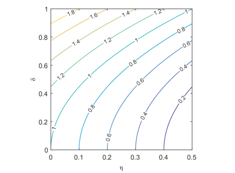
which is similar to that of the red-detuned system when replacing with . In a similar fashion, one can show that in this case a large cooperativity results in ideal circulation, however, this is an unphysical scenario given that in the blue-detuned regime large cooperativities give rise to parametric instabilities. On the other hand, the S matrix of Eq. (S2) exhibits interesting properties and can become close to that of an ideal circulator for critical choices of the parameters involved. Interestingly, compared to the red-detuned case, here the circulation direction is reversed, i.e., can be close to unity while are minimum. In fact, for a particular set of parameters, one can show that and become zero for
| (S3) | ||||
| (S4) |
which clearly requires equal leakage rate for both channels . In addition, these conditions demand a total cooperativity larger than the ratio of internal loss to total losses (). Figure S5 depicts the cooperativity required to satisfy this condition for different values of and . Interestingly, the choice of demands a cooperativity of which instead results in the following resonant S matrix:
| (S5) |
According to this simple relation, near-ideal circulation can be achieved for and . On the other hand, one can reduce the reflection coefficients and diagonal port couplings by decreasing which instead requires a decrease in . This latter scenario thus happens for a weak waveguide-cavity coupling.
Section S4 Parametric instability threshold
For a blue-detuned control laser, the optomechanical system can enter a parametric instability regime. For a single-mode optomechanical system, the threshold cooperativity associated with the onset of instabilities is found to be . Similar relation holds for the microtoroid system when assuming a degenerate pair of counter rotating modes where only one of the modes is populated by the control laser. However, assuming a finite coupling between the two modes, this relation is no longer valid. In this case, one would expect a higher cooperativity for bringing the system to instability threshold given that the active mode is coupled to another mode which is naturally lossy. For a blue-detuned system, the dynamical equations governing the optomechanical system in the absence of input probe signals can be written as:
| (S6) |
Assuming and , we consider an ansatz of , which results in the following cubic equation for the exponent
| (S7) |
The stability of the system can now be investigated by finding a parameter regime for which all roots of this equation fall on the left side of the imaginary axis, i.e., . This latter can be obtained through the Routh-Hurwitz stability criterion. According to the Routh-Hurwitz criterion, a generic cubic equation of the form has all roots in the negative real part plane as long as , and . For Eq.(S7), the stability conditions are found to be:
| (S8) |
| (S9) |
Given that in practice , the first condition imposes a lower bound on the control power required to bring the system to instability threshold. Therefore, by rewriting Eq. (S8) in terms of the total cooperativity, the condition of stability can be written as , which results into the following expression for the instability threshold
| (S10) |
This relation assures that the condition of near-ideal circulation (Eq.(S3)) is accessible without running into instability. It is worth noting that this condition is obtained under the rotating wave approximation. A more general expression can be found when considering both mechanical sidebands.
Section S5 Circulation bandwidth
According to the results presented in the main text, the bandwidth of the optomechanical circulator is dictated by the linewidth of the optomechanically induced transparency (OMIT) or absorption (OMIA) window. Considering the -matrix derived in the Materials and Methods section, the bandwidth can be obtained through the frequency-dependent factor of ,
| (S11) |
where, to simplify the analysis, we have assumed equal losses in both modes, , and equal intensity pumping, . In this relation the up and down signs are associated with the red- and blue-detuned regimes respectively. Given that in general , the inverse optical susceptibilities are fairly constant near the resonance and over the small frequency range of OMIT/OMIA. Thus one can assume which greatly simplifies Eq.(S11) to
| (S12) |
According to this relation, the transparency or absorption window is found to be
| (S13) |
which, could be compared with a similar relation for a single-mode optomechanical cavity: . Recalling that is a normalized mode splitting, relation (S13) shows that in general the lifted degeneracy of the modes decreases the bandwidth in the red-detuned regime while it increases the bandwidth in the blue-detuned case. In addition, relation (S13) is in agreement with the fact that the bandwidth should approach zero at the onset of parametric instabilities.
Section S6 Thermal noise
Thermal phonons in the mechanical resonator interact with the control beam creating cavity photons that contribute to noise at the output ports of the device. The effect of thermal noise can be considered in the linearized mechanical equation of motion as:
| (S14) |
where is the noise operator with correlations and where is the thermal occupation number of the mechanical mode. The coupled optomechanical equations of motion can now be used to write the frequency-domain contribution of noise to all four ports in terms of the noise operator . Under the rotating wave approximation, the output noise operators for a red-detuned system are found to be:
| (S15) |
while, for a blue-detuned control laser, we have:
| (S16) |
where,
| (S17) |
Here, the mechanical and optical susceptibilities are defined as and . The power spectral density of the thermal photon flux at output ports can be obtained as . To simplify the analysis, we assume that the optical modes have equal losses (, , , ) and are driven out of phase with equal intensities such that . The noise contribution at each port then reads
| (S18) |
where is the Boltzmann constant, and is the bath temperature.
On resonance () the noise contribution can be written as
| (S19) |
where the upper and lower signs correspond to red- and blue-detuned controls respectively. Figure S6 plots the output noise at port 2 for the case of red- and blue-detuned controls as a function of the cooperativity.