Formation of freely floating sub-stellar objects via close encounters
Abstract
Aims. We numerically studied close encounters between a young stellar system hosting a massive, gravitationally fragmenting disk and an intruder diskless star with the purpose to determine the evolution of fragments that have formed in the disk prior to the encounter.
Methods. Numerical hydrodynamics simulations in the non-inertial frame of reference of the host star were employed to simulate the prograde and retrograde co-planar encounters. The initial configuration of the target system (star plus disk) was obtained via a separate numerical simulation featuring the gravitational collapse of a solar-mass pre-stellar core.
Results. We found that close encounters can lead to the ejection of fragments that have formed in the disk of the target prior to collision. In particular, prograde encounters are more efficient in ejecting the fragments than the retrograde encounters. The masses of ejected fragments are in the brown-dwarf mass regime. They also carry away an appreciable amount of gas in their gravitational radius of influence, implying that these objects may possess extended disks or envelopes, as also suggested by Thies et al. (2015). Close encounters can also lead to the ejection of entire spiral arms, followed by fragmentation and formation of freely-floating objects straddling the planetary mass limit. However, numerical simulations with a higher resolution are needed to confirm this finding.
Key Words.:
protoplanetary disks – stars: formation – stars: protostars – brown dwarfs – hydrodynamics1 Introduction
Most stars do not form in isolation but in associations or clusters, and encounters between young stars in the clusters are a natural outcome of the star formation process caused by its turbulent nature (e.g. Kroupa, 1995; Lada & Lada, 2003; Bate, 2009). Encounters can significantly influence the evolution of protostellar disks, which has been confirmed by numerical studies combining cluster simulations with simulations of individual encounters (e.g. Pfalzner, 2008; Pfalzner et al., 2008; Rosotti et al., 2014). Among the expected effects are the truncation of disks and enhanced accretion rates. In addition, various more detailed simulations of individual encounters have been performed (e.g. Shen & Wadsley, 2006, 2010; Forgan & Rice, 2009, 2010; Thies et al., 2010; Muñoz et al., 2015), investigating the role of encounters in FU Orionis outbursts, brown dwarf formation, disk instability, truncation of disks, and binary capture. In particular, Thies et al. (2010) demonstrated that a close encounter can trigger gravitational fragmentation in the disk of a target which is otherwise stable to fragmentation.
None of these studies, however, considered encounters which involved a disk that was already prone to fragmentation before the encounter. Such disks are expected to exist in the early embedded stages of evolution (e.g. Machida et al., 2010; Vorobyov, 2011; Tsukamoto et al., 2013; Dunham et al., 2014). Moreover, the likelihood of encounters with young systems with still massive and extended disk is expected to be higher than with their old counterparts because the cluster members spread around with age due to dynamical scattering. For instance, Thies et al. (2010) estimated that an average star in an Orion-type cluster can experience an encounter with a periastron radius below several hundred AU with a probability of , while being young and hosting a massive and extended disk.
Encounters involving fragmenting disks can be more complex, as the approaching star does not only interact gravitationally with the disk, but also with the fragments. This might lead to perturbations of the fragment trajectories, leading to scattering or even ejection of fragments formed in the disk before the encounter. This may provide a source of freely floating brown-dwarf and even planetary-mass objects, in addition to those that may be ejected from the disk via internal multi-body interactions (Stamatellos & Whitworth, 2009; Bate, 2009; Basu & Vorobyov, 2012; Vorobyov, 2016).
In this paper, the collision scenario is explored with numerical hydrodynamics simulations featuring a close, co-planar passage of a Solar-type star with a massive, fragmenting disk around a star. To generate realistic disk configurations, we ran our model from the gravitational collapse of a pre-stellar core until the central star and disk were formed and initiated the collision with the intruder when the age of the system was 0.42 Myr and the mass of the disk was of . At this time instance, the disk already featured several fragments formed via gravitational fragmentation.
2 Model description
In this section, the main features of the numerical model used for studying close encounters with young protostellar disks are summarized. To compute the formation and early evolution of protostellar disks, we employed the numerical hydrodynamics code described in detail in Vorobyov & Basu (2015). This code was further modified to include the close passage of an intruder star represented by a gravitating point source. We start our numerical simulations from the gravitational collapse of a prestellar cloud core, continue into the embedded phase of star formation, during which a star and disk are formed, and terminate our simulations when less than 10% of the initial core mass remains in the envelope. To accelerate the computations, we use the thin-disk approximation (for justification see Vorobyov & Basu, 2010).
To avoid too small time steps, we introduce a sink cell at AU. The sink cell is dynamically inactive; it contributes only to the total gravitational potential and secures a smooth behavior of the gravity force down to the stellar surface. During the early stages of the core collapse, we monitor the gas surface density in the sink cell and when its value exceeds a critical value for the transition from isothermal to adiabatic evolution, we introduce a central point-mass star. In the subsequent evolution, 90% of the gas that flows to the sink cell is assumed to land on the growing star. The other 10% of the accreted gas is assumed to be carried away with protostellar jets. When the in-spiralling material of the collapsing core hits the centrifugal barrier near the sink cell the protostellar disk starts to grow, occupying the inner part of the numerical polar grid. In the embedded phase of disk evolution, the disk is exposed to intense mass-loading from the infalling envelope, which increases the disk mass and triggers the onset of gravitational instability. The disk becomes prone to fragment usually in the Class I phase when the disk mass and size are the largest. In the early T Tauri phase when the parental core nearly dissipates via accretion, we launch the intruder towards the newly formed star plus disk system and further follow the dynamics of the encounter for several tens of thousand years.
2.1 Disk hydrodynamics equations
The equations of mass, momentum, and energy transport describing the dynamics of circumstellar disks in the thin-disk limit can be formulated as follows:
| (1) |
| (2) | |||||
| (3) |
where is the mass surface density, is the internal energy per surface area, is the vertically integrated gas pressure calculated via the ideal equation of state as with , is the velocity in the disk plane, and is the gradient along the planar coordinates of the disk. The gravitational accelerations in the disk plane, and , take into account self-gravity of the disk and the gravity of the central protostar when formed. Disk self-gravity is found by solving for the Poisson integral:
| (4) | |||||
where and are the radial positions of the computational inner and outer boundaries. This integral is calculated using a FFT technique which applies the 2D Fourier convolution theorem for polar coordinates and allows for the non-periodic boundary conditions in the -direction by effectively doubling the computation domain in this coordinate direction and filling it with zero densities (see Binney & Tremaine, 1987, Sect. 2.8).
The evolution of isolated circumstellar disks is usually computed in the inertial frame of reference, in which the position of the star is fixed in the coordinate center. This approach is justified for as long as the gravitational influence of the disk on the star is negligible, which is true for low-mass, nearly-axisymmetric disks. However, the intruder will exert a strong gravitational pull on the target star so that it cannot be anymore considered as motionless. In addition, young massive disks are often non-axisymmetric so that the superposition of gravity forces acting on the star from the disk may also be non-zero, causing the star to move (or wobble) in response. The grid-based methods applied to studying the disk dynamics often use cylindrical or spherical coordinate systems, which are naturally centered on the star. However, the use of curvilinear coordinate systems with a singularity point in the coordinate center makes it extremely difficult to calculate directly the stellar motion and its gravitational response to the disk and/or intruder. To circumvent this problem, a non-inertial frame of reference is often introduced, which moves with the star (positioned in the coordinate center) in response to the net gravitational force of the disk and/or intruder. The resulting acceleration of the star can be described as
| (5) |
where is a mass element in the disk with position vector , is the mass of the intruder and is the position vector of the intruder. The term that has to be added to the total gravitational acceleration thus is . This term can be expressed as the derivative of a potential, the so-called indirect potential ; the details of calculating are provided in Regály & Vorobyov (2017). The details on how the gravitational acceleration from the intruder is calculated will be provided in Section 2.2.
Turbulent viscosity is taken into account via the viscous stress tensor , the expression for which can be found in Vorobyov & Basu (2010). The kinematic viscosity needed to calculate the viscous stress tensor is found adopting the Shakura and Sunyaev parameterization (Shakura & Sunyaev, 1973), so that , where is the sound speed and is the disk scale height calculated from the assumption of local hydrostatic balance in the disk. In this work, we use a spatially and temporally constant .
The radiative cooling per surface area in Equation (2) is determined using the diffusion approximation of the vertical radiation transport in a one-zone model of the vertical disk structure (Dong et al., 2016)
| (6) |
where and are the Rosseland and Planck optical depths to the disk midplane, and the Planck and Rosseland mean opacities, the gas surface density from the disk surface to the midplane, and a form of the midplane gas temperature.
The heating function per surface area of the disk is expressed as
| (7) |
where is the irradiation temperature at the disk surface determined by the stellar and background black-body irradiation as
| (8) |
where is the uniform background temperature (in our model set to the initial temperature of the natal cloud core) and is the radiation flux (energy per unit time per unit surface area) absorbed by the disk surface at radial distance from the central object. The latter quantity is calculated as
| (9) |
where is the incidence angle of radiation arriving at the disk surface at radial distance . The incidence angle is calculated using the disk surface curvature inferred from the radial profile of the disk vertical scale height at each time step (Vorobyov & Basu, 2010). The stellar luminosity is the sum of the accretion luminosity arising from the gravitational energy of accreted gas and the photospheric luminosity due to gravitational compression and deuterium burning in the stellar interior. The stellar mass and accretion rate onto the star are determined using the amount of gas passing through the sink cell, while the stellar radius and are returned by the Lyon stellar evolution code (Baraffe & Chabrier, 2010).
Equations (1)–(3) are solved in the polar coordinates on a numerical grid with grid zones. The solution procedure is similar in methodology to the ZEUS code (Stone & Norman, 1992) and is described in detail in Vorobyov & Basu (2010). We impose a free outflow boundary condition so that the matter is allowed to flow out of the computational domain but is prevented from flowing in. Once the intruder is launched, the outer boundary condition is switched to the free inflow/outflow (and not only outflow) one. This is done to prevent artificial rarefaction of matter near the outer boundary in the non-inertial frame of reference moving with the target star.
2.2 Description of the intruder
Because of the adopted thin-disk approximation, the motion of the intruder is restricted to the disk plane. Coplanar encounters are expected to have the highest impact on the disk (Forgan & Rice, 2009) and our numerical code is best suited for this type of encounters. The equations of motion for the intruder moving in a combined gravitational potential of the target star and the disk, written as first order differential equations in polar coordinates, are given by
| (10) | |||||
| (11) | |||||
| (12) | |||||
| (13) |
with the acceleration calculated as
| (14) |
where is the force the intruder experiences from a single grid cell, given in equation (16), and the summation is performed over all grid cells. To calculate the trajectory of the intruder, equations (10)-(13) are solved using a Dormand-Prince method (a fifth-order Runge-Kutta method) with adaptive stepsize control (see Press et al., 2007, chap. 17.2). Several tests were performed to demonstrate that the code is producing correct results (Steinrueck, 2015).
2.2.1 Intruder-Disk interaction
To calculate the influence of the intruder on the gas dynamics in the disk, the gravitational potential of the intruder is added to the total potential on each grid point in the hydrodynamics code. The gravitational potential of the intruder at a grid cell with indices and is given by
| (15) |
where is the smoothing radius and is given by equation (17). The symbol is used for the vector pointing from the intruder towards the center of the grid cell and the distance between the grid cell and the intruder is denoted by .
2.2.2 Disk-Intruder interaction
The force that the disk exerts onto the intruder is calculated by summing the contributions from each cell, treating the cells as point masses with mass . The contribution from an individual cell is given by
| (16) |
with defined in equation (18). As the summation is computationally expensive, the forces are updated only once per hydrodynamical timestep.
2.3 Gravitational softening
The gravitational forces between the gas and the intruder can become extremely strong if the intruder approaches one of the cell centers, where all mass is concentrated according to our convention. To avoid this unphysical behavior, the potential has to be modified for small distances. We use the same potential as in Klahr & Kley (2006), where the potential for distances smaller than a smoothing radius is set to
| (17) |
At the smoothed potential and its first and second derivatives agree with the unaltered potential and its derivatives. The advantage of this choice is that it only modifies the potential for distances smaller than , unlike the common approach .
The modified force that a single grid cell with a distance from the intruder smaller than exerts on the intruder is then given by
| (18) |
The choice of the smoothing radius is not trivial. If it is too small, the gravitational interaction of the gas and the intruder will be overestimated, a too large will underestimate the forces. As the smoothing is introduced to compensate discretization effects, it seems plausible that the smoothing radius has to be related to the cell size:
| (19) |
where and are the local cell spacings in the radial and azimuthal direction. Testing different smoothing radii shows that results in unexpectedly strong interactions with the disk, altering the trajectory of the intruder more than expected, while there is relatively little difference between and . We therefore choose throughout the simulations.
3 Initial conditions and the early disk evolution
To obtain a realistic initial disk configuration, a simulation of the collapse of a cloud core was run, similar to the simulations in Vorobyov & Basu (2015). The initial surface density and angular velocity profiles of the core are as follows
| (20) | |||||
| (21) |
where and are the gas surface density and angular velocity at the center of the core. These profiles have a small near-uniform central region of size and then transition to an profile; they are representative of a wide class of observations and theoretical models (André et al., 1993; Dapp & Basu, 2009). For the chosen AU, g cm-2, and km s-1 pc-1, the total mass of the core is and the ratio of rotational to gravitational energy is .
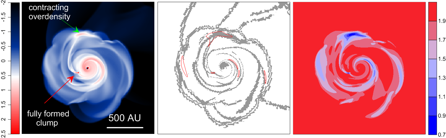
We choose the disk configuration at Myr after the onset of the core collapse as the initial setup for all simulations including the intruder. At this time, the central star has a mass of and the disk mass is 0.25 . The surface density inside 1000 AU from the star at this time is plotted in the left-hand-side panel of Figure 1. The disk extends to around 500 AU from the central star and is gravitationally unstable as is manifested by a well-developed spiral structure. There is one fragment present in the disk to the left of the central star (shown with the red arrow). At the top, at around 500 AU distance from the central star, an overdensity can be seen (shown with the green arrow). Soon afterwards it collapses and forms another fragment.
To check if the the conditions in the disk fulfill the known fragmentation criteria, we plot in the middle panel of Figure 1 the spatial distribution of the Toomre -parameter, and the Gammie -parameter defined as (Gammie, 2001), where is the local cooling time. We note that if , cooling turns into heating and both the cooling time and the Gammie criterion become formally negative. The gravitationally unstable disk is expected to fragment if and . The numerical values in both criteria may vary somewhat depending on physical conditions in the disk and resolution (Meru & Bate, 2011; Takahashi et al., 2016; Boss, 2017), but we have chosen the conservative values. The disk regions where the Q-parameter is smaller than unity are shown with the red contour lines, while the regions where the -parameter is smaller than 3.0 are plotted with the grey color. Clearly, the contracting overdensity fulfills both criteria. The same can be said about the already existing fragment. However, there are several regions in the disk where the -parameter is smaller than unity, but the -parameter is greater than 3.0. These regions show no sign of fragmentation.
Finally, we check if the Truelove criterion (Truelove et al., 1998), stating that the Jeans length should be resolved by at least 4 grid cells in each coordinate direction, is fulfilled. In the thin-disk limit, the Jeans length is defined as , where is the velocity dispersion in the disk plane (Vorobyov, 2013). The right-hand-side panel in Figure 1 presents the ratio (in log scale) calculated for every grid cell in the disk, where and are the grid spacings in the radial and azimuthal direction. The minimum of is found at the centers of the forming and already formed fragments. In the most relevant case of the forming fragment (we do not expect a secondary fragmentation in the already formed fragment), the minimum value of is 5 at the center of the forming fragment and increases to 10 around the fragment, meaning that the Jeans length is resolved. The ratio is greater than 10 in the rest of the disk.
4 Results
| Model | (km/s) | (km/s) | (deg) | expected periastrona (AU) | actual periastron (AU) | Fragment ejected? |
|---|---|---|---|---|---|---|
| P1 | -1.8 | 0.5 | 90 | 473 | 412 | yes |
| P2 | -2.1 | 0.7 | 90 | 704 | 659 | yes |
| P3 | -1.9 | 0.6 | 90 | 606 | 556 | yes |
| P4 | -1.7 | 0.45 | 90 | 410 | 338 | yes (2) |
| P5 | -1.8 | 0.5 | 180 | 473 | 391 | yes (2) |
| P6 | -1.8 | 0.5 | 270 | 473 | 467 | yes (2) |
| R1 | -1.8 | -0.5 | 90 | 473 | 466 | yes |
| R2 | -2.1 | -0.7 | 90 | 704 | 700 | no |
| R3 | -1.9 | -0.6 | 90 | 606 | 601 | no |
| R4 | -1.7 | -0.45 | 90 | 410 | 397 | no |
| R5 | -1.8 | -0.5 | 270 | 473 | 423 | no |
| R6 | -1.8 | -0.5 | 0 | 473 | 384 | no |
The columns show, from left to right, the model identifier (the names of prograde models start with P, the ones of retrograde models with R), radial and azimuthal components of the initial velocity of the intruder and , the initial azimuthal position of the intruder , expected (calculated analytically treating the disk-star system as a point mass) and actual periastron radius and whether fragments have been ejected during the simulation.
In this section, we presents the results of numerical simulations showing the outcome of collisions between a point-mass intruder star and a target star hosting a massive, gravitationally unstable disk that has already formed several fragments. We considered several models of encounters with a mass of the intruder star . The intruder is added to the simulation at Myr at a distance of 3000 AU, far enough to avoid any effects from the sudden appearance of the intruder on the disk of the target. Table 1 presents the overview of our simulations. In total, we have run 12 models with different initial velocities of the intruder: 6 out 12 models are characterized by the prograde trajectory of the intruder with respect to the disk of the target and the rest have retrograde trajectories. All encounters are coplanar with the disk of the target. We have found several interesting phenomena related to collisions of the intruder star with the disk of the target which we describe in detail below.
4.1 Ejection of existing fragments
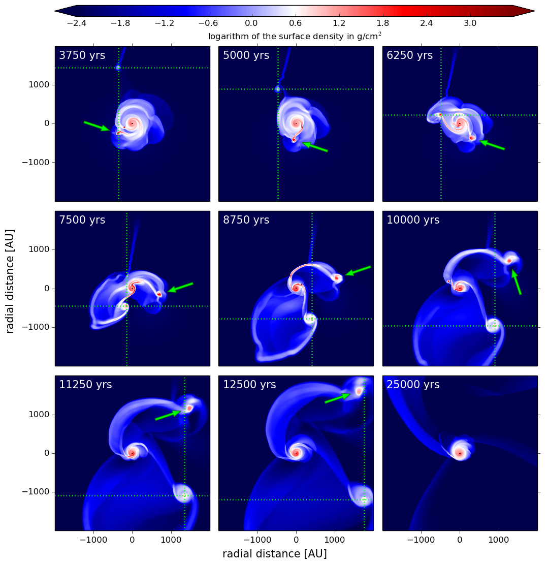
In the majority of the prograde models, one of the fragments is later ejected from the disk due to three-body interaction between the intruder, the target star and the fragment itself. Figure 2 illustrates this process with a series of simulation snapshots from Model P1. Each panel shows the surface density in g cm-2 on a logarithmic scale in a 4000 AU x 4000 AU box centered around the target star. In this figure, as well as in all other figures showing simulation snapshots, the position of the intruder is indicated by the intersection of the dotted lines. The position of the ejected fragment is highlighted by an arrow. The time shown is elapsed since the launch of the intruder.
In the initial stages, the approaching star is clearly visible thanks to a gas tail which the intruder leaves in its wake when passing through the remnant envelope surrounding the target system. The closest approach occurs at around yr with a periastron distance of 412 AU. By this time, the inner, less massive fragment (shown by the red arrow in Figure 1) has migrated into the inner disk regions and dispersed by the action of tidal torques, but the outer, more massive fragment formed from a contracting overdensity (shown by the green arrow in Figure 1) has survived the encounter and gained angular momentum via the three-body gravitational interaction between the intruder star, target star+disk system and the fragment itself.
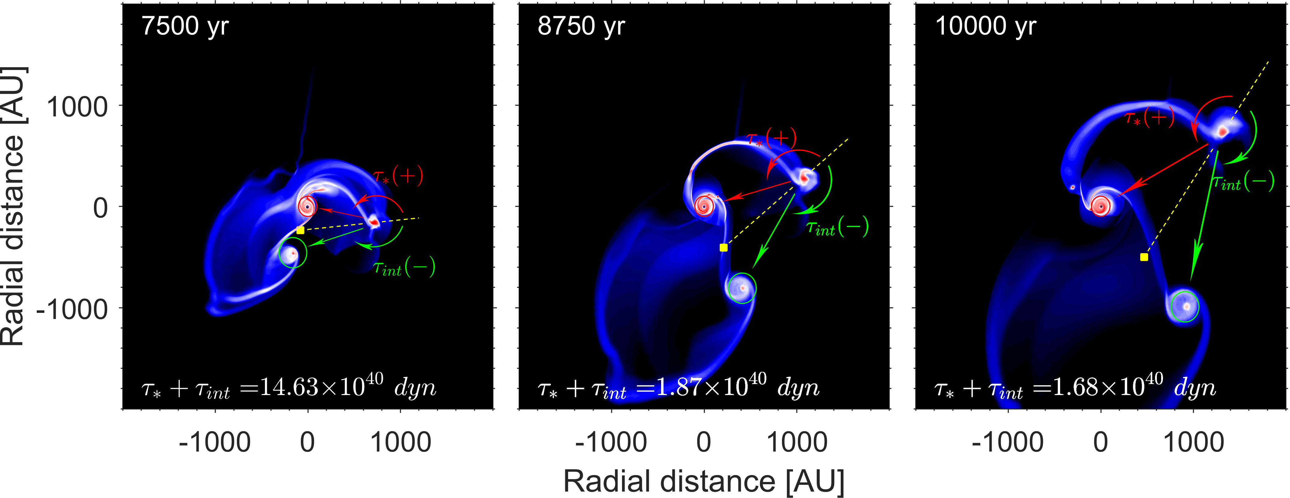
Figure 3 illustrates the ejection mechanism and shows schematically the gravitational forces and torques acting on the ejected clump from the target star and the intruder at three consecutive times corresponding to the middle row in Figure 2. In particular, the red and green arrows show the gravity forces acting on the ejected clump from the target star and intruder, respectively. When calculating these forces, we considered the total masses of the target star and the intruder including the gas disks around them (outlined by the red and green circles, respectively). The yellow square marks the center of mass of the host star and the intruder (including their disks) and the dashed yellow line represents the arm. The gravitational torques acting on the ejected clump from the host star and the intruder are shown by the curved red and green arrows, respectively. Because the clump orbits the host star in the counter-clockwise direction, is positive and is negative. The sum of the two torques is always positive, as indicated in each panel, meaning that the clump gains angular momentum. Once its kinetic energy becomes greater than the potential gravitational energy (see Table 2), it permanently leaves the system.
To calculate the mass of the ejected fragments, we employed the fragment tracking algorithm described in detail in Vorobyov (2013). Namely, two conditions were used: 1) the fragment must be pressure supported, with a negative pressure gradient with respect to the center of the fragment; and 2) the fragment must be kept together by gravity, with the potential well being deepest at the center of the fragment. The resulting masses of the ejected fragments, along with their other characteristics, are presented in Table 2.
| Model | (MJup) | (MJup) | (km/s) | (km/s) | |
|---|---|---|---|---|---|
| P1 | 24 | 45 | 1.67 | 2.20 | 3.32 (CM) |
| P2 | 21 | 40 | 1.18 | 2.80 | 2.93 (S) |
| P3 | 23 | 41 | 1.37 | 2.56 | 4.54 (S) |
| P4 | 25 | 44 | 1.46 | 1.65 | 1.75 (CM) |
| P6 | 10 | 23 | 1.88 | 2.15 | 2.92 (CM) |
| R1 | 10 | 25 | 2.13 | 3.33 | 7.32 (CM) |
The columns show, from left to right, the fragment mass , the mass located inside the fragment’s Hill radius , the velocity of the fragment relative to the disk central star and the intruder , and the ratio of kinetic to potential energy in the reference frame in which this ratio is the lowest with the reference frame indicated in brackets (CM=center of mass system, S=central star).
With only slight variations between different models, the mass of the ejected fragment is 20–25 Jupiter masses. An exception is Model P6 with 10 MJup, as the intruder passes the fragment relatively close, such that the fragment loses part of its mass via tidal stripping. There is an additional amount of gas with 40–45 MJup (23 MJup in Model P6) located inside the Hill radius of the fragment. This mass may be accreted by the fragment and its final mass is likely to be in the brown dwarf regime. Thus, the fragment resembles a proto-brown dwarf. A fraction of the material in the Hill radius may form an accretion disk, as observed around some young brown dwarfs (e.g. Riaz et al., 2016). The ratio of kinetic to gravitational potential energy of the ejected fragment in Table 2 is greater than unity, implying that we witness true ejection and not gravitational scatter to some eccentric orbit around the target star. Table 2 also indicates that the ejection velocities are a few km s-1, which is consistent with the mean velocities of brown dwarfs in young star forming regions (e.g. Kroupa & Bouvier, 2003; Joergens, 2006). For instance, Kroupa & Bouvier write in their abstract “It is shown here that these results can be understood if brown dwarfs are produced as ejected embryos with a dispersion of ejection velocities of about 2.0 km s-1, and if the number of ejected embryos is about one per four stars born in Taurus-Auriga and the Orion Nebular cluster”.
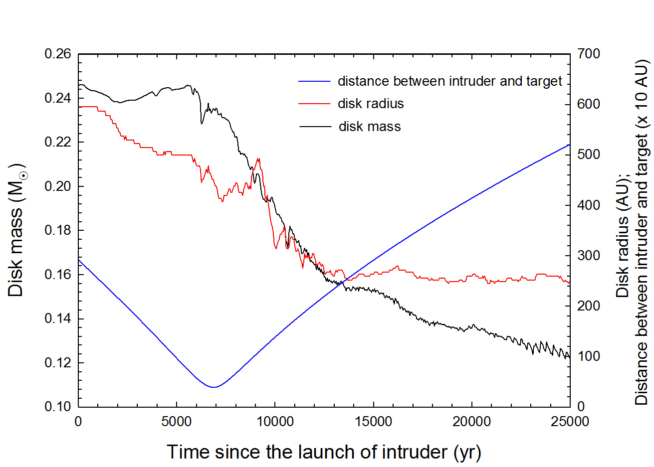
An important effect that was also reported in previous simulations with close encounters (e.g. Pfalzner, 2008) is truncation of the disk around the target star. This phenomenon is illustrated in Figure 4 showing the time evolution of the disk mass and radius (the black and red lines, respectively) along with radial distance of the intruder from the target star (the blue line) in model P1. Clearly, the collision of the intruder with the disk around the target star causes a significant reduction in the disk mass and size. While before the collision, the disk mass and radius were and 550 AU, 18000 yr after the closest approach the respective values are and AU. The truncated disk still shows signs of gravitational instability as manifested by flocculent spiral arms, but is stable against gravitational fragmentation. It is also evident that the intruder captures and retains some material from the target disk. This material later forms a compact rotating gaseous disk around the intruder. We also note that accretion of disk material onto the intruding star has been studied by Thies et al. (2011) and Xiang-Gruess & Kroupa (2017) who showed that this process may be important for the formation of misaligned hot Jupiters.
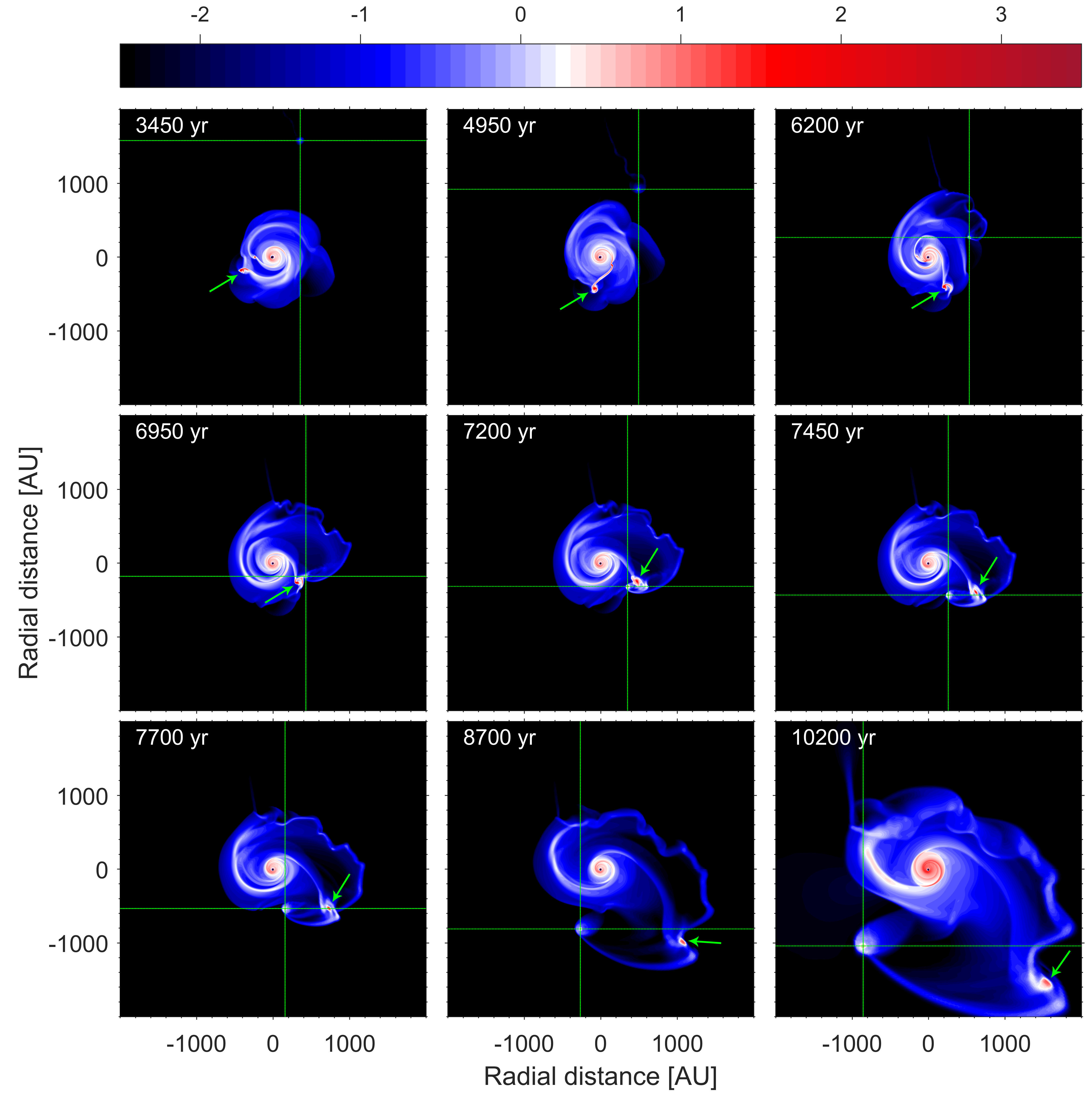
In most of the models in which the intruder has a retrograde trajectory, no ejections are observed. This may be related to the fact that in retrograde collisions the net angular momentum of the involved constituents: the intruder, the target, and the target disk (including fragments) is smaller as compared to the case with prograde collisions, making ejections a less likely outcome. Figure 5 (model R1), however, presents a spectacular exception. In this model, the intruder passes the fragment (shown by the green arrow) very closely and catapults the fragment out of the system by means of its gravitational pull. The ejection process is illustrated in Figure 5, showing the surface density at nine consecutive time instances. In the top row, the intruder approaches the fragment. The closest approach to the fragment, with a distance of AU, happens in the middle row. As can be seen, the fragment gets highly distorted due to tidal forces and loses part of its mass. The bottom row shows how the fragment leaves the system. The ejection in retrograde collisions requires therefore a close encounter, which is expected to be a rare event. For comparison, the distance between the intruder star and the ejected fragment in the prograde model P1 at the closest approach to each other is about 1000 AU.
| Model | (MJup) | (MJup) | (km/s) | (km/s) | |
|---|---|---|---|---|---|
| P4 | 9 | 13 | 1.20 | 2.08 | 3.03 (S) |
| P5 | 9 | 21 | 1.39 | 2.47 | 2.94 (S) |
| 5 | 14 | 1.22 | 2.26 | 2.06 (S) | |
| P6 | 10 | 24 | 1.46 | 2.21 | 3.25 (CM) |
4.2 Ejection of spiral arms followed by their gravitational fragmentation
A close encounter of an intruder star with a massive disk may lead to a direct ejection of fragments that have formed in the disk before the encounter event. However, a fly-by of the intruder may also trigger ejection of dense elements of spiral arms essentially via the same multi-body gravitational interaction. Figure 6 illustrates this phenomenon and presents the surface density in a AU2 box centered around the target star in model P4. The surface density is plotted at nine consecutive instances since the launch of the intruder star. Arrow 1 points to the pre-existing massive fragment, which is scattered and dispersed soon after the encounter with the intruder star, likely because of strong gravitational perturbation and tidal torques during the close encounter. At the same time, a dense spiral arm shown by Arrow 2 is ejected from the disk of the target star. Two clumps form in the spiral arm close to each other and are ejected in the same direction. Due to the decreasing resolution of the logarithmically spaced grid they merge at a distance of AU from the central star. However, a determination of the fragment masses, positions and velocities at AU shows that they are not bound to each other. A similar phenomenon was observed also in models P4 and P6.
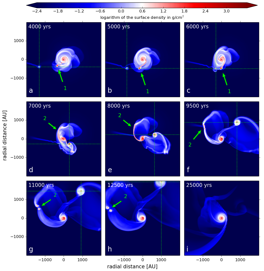
Table 3 presents the properties of fragments formed in ejected spiral arms. It is interesting to note that with masses ranging from 5 to 10 and gas masses located inside the Hill radius between 13 and 24 , the fragments formed in tidal arms are less massive than the fragments ejected from the disk. This is because they form at a larger distance from the star, where the temperatures are lower, corresponding to a lower Jeans mass. It is likely that the fragments will accrete a fraction of the mass inside the Hill radius, though it is not clear how much exactly. Therefore, the fragments will form either low-mass brown dwarfs or free-floating planetary-mass objects. The masses of ejected objects in our models lie in a narrower mass range of 5–25 (not taking the mass in the Hill radius into account) and are skewed towards lower masses than what was found in other numerical studies on the ejection phenomenon (e.g. Stamatellos & Whitworth, 2009; Thies et al., 2010; Basu & Vorobyov, 2012; Thies et al., 2015; Vorobyov, 2016). For instance, Thies et al. (2010,2015) reported the masses of ejected objects to lie in the 14–84 range. Vorobyov (2016) found a similar range of 21–145 , but shifted somewhat to higher masses. The reason for a narrower mass range in our study is that we considered encounters with only one disk model and varied the initial impact parameters. We expect a better agreement once more disk models with different preexisting characteristics of fragments are considered. Our models also seem to allow for lower masses of ejected objects than normally found in other studies. This may be caused by either a limited range of parameter space in other works, as was already noted in Thies et al. (2010,2015), or by intrinsic properties of encounter-triggered ejections leading to tidal truncation of ejected fragments and allowing for ejection of entire spiral arms followed by fragmentation. We note that our calculated masses can be brought to better agreement with other studies, if the mass in the Hill radius is added to the mass of ejected fragments. The fraction of the mass in the Hill radius that will finally end up in the central object is however highly uncertain.
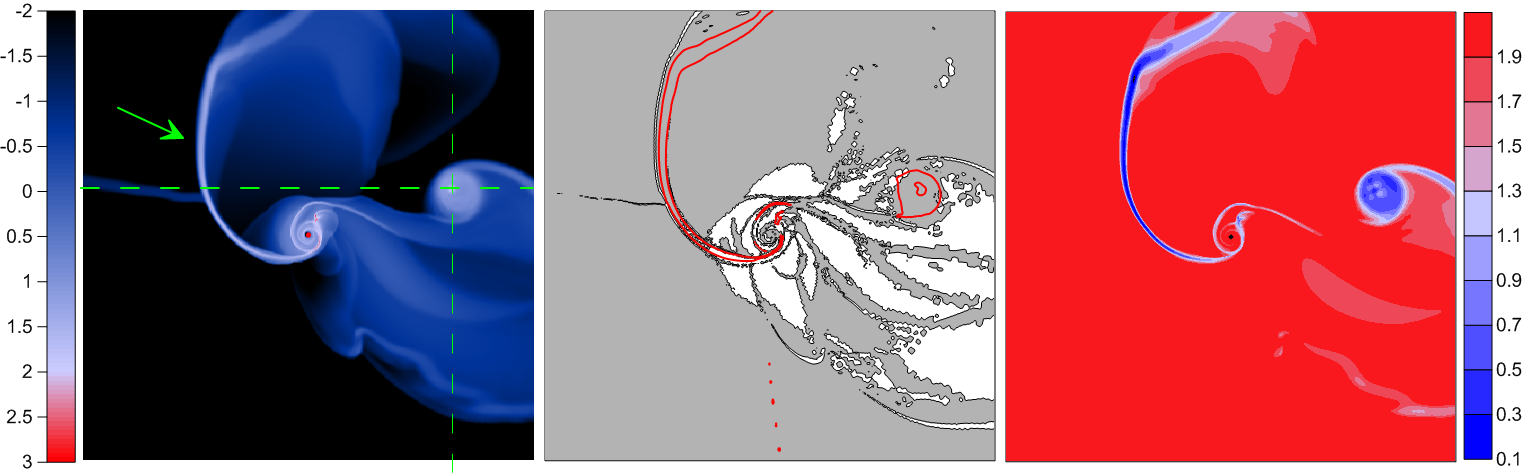
To check if the known fragmentation criteria are fulfilled in the ejected spiral arm, we calculate the Toomre -parameter, the Gammie -parameter and the ratio of the Jeans length to the local grid spacing in a similar manner as was done in Section 3. The results are shown in Figure 7 for a time instance of yr after the launch of the intruder, just before the spiral arm forms two distinct fragments. Clearly, the ejected spiral arm is characterized by the Toomre parameter and by the Gammie parameter , fulfilling these fragmentation criteria. At the same time, the minimum value of in the ejected arm is about 2 and it increases to 3–5 in some parts of the arm, meaning the the Truelove criterion may not be resolved in the entire spiral arm. The ejected spiral arms are colder than the disk and they have smaller Jeans lengths. Therefore, numerical simulations with a higher numerical resolution are needed to fulfil the Truelove criterion in the entire ejected arm and confirm that fragmentation in ejected spiral arms is not a numerical resolution effect.
We note that all of the ejections of fragments formed in spiral arms happen in prograde encounters. This is because prograde encounters form more extended tidal structures, a behavior that has been observed in previous studies of encounters as well (e.g. Shen et al., 2010; Forgan and Rice, 2009).
5 Discussion and model caveats
The formation mechanism of isolated brown dwarfs is traditionally attributed to the gravitational collapse of compact and dense pre-stellar cores, often complemented by some mechanisms that can stop accretion onto the central object before it can grow beyond the brown-dwarf mass regime (Whitworth & Zinnecker, 2004; Padoan & Nordlung, 2004; Chabrier & Hennebelle, 2011). An alternative is the disk ejection mechanism when finished brown dwarf or their embryos are first formed in gravitationally unstable disks and then ejected into the intracluster medium (Stamatellos & Whitworth, 2009; Basu & Vorobyov, 2012; Vorobyov, 2016). We note, however, that ejections due to internal multi-body gravitational interaction between the host star and fragments require at least two fragments (or finished brown dwarfs) to co-exist in the disk. These two fragments should also approach each other quite closely, from several to tens of AU depending on their masses, to gain enough momentum and be ejected from the disk.
On the other hand, prograde encounters with intruder stars do not require a close approach for the fragment to be ejected. Our modeling shows that an approach of about 1000 AU between the fragment and the intruder is sufficient for the fragment to be ejected (see model P1). We note that such encounters may be present in the early disk evolution (e.g. Thies et al., 2010), when disk gravitational fragmentation is also most likely (Vorobyov & Basu, 2010). In addition, only one fragment is sufficient to pre-exist in the disk. Both arguments increases the probability of fragment ejection via close encounters with intruder stars. We note that those fragments that are not ejected directly as a result of stellar encounter may end up on highly eccentric orbits with large semi-major axis of hundreds of AU. These highly eccentric objects may be removed from the primary star later on through stellar-dynamical perturbations from passing stars within the birth cluster. Thus, even initially not ejected fragments or proto-brown dwarfs may end up being dissociated from their central star, increasing the net ejection efficiency.
Finally, we want to mention several caveats to our modeling that need to be addressed in the future studies. As was already mentioned in Section 4.2, numerical simulations with higher resolution are needed to confirm that fragmentation in ejected spiral arms is not a numerical resolution effect. In addition, the effect of accretion on the intruder star and heating due to the intruder luminosity need to be addressed. In the current version, heating due to radiation of the host star is only included. Non-planar encounters need also to be studied. In this case, the gravitational force acting from the intruder on the clump will torque the clump off the plane of the disk, potentially leading to misaligned orbits of the clumps. Whether these clumps can still be ejected or rather form a population of bound but misaligned sub-stellar objects remains to be understood. Finally, a parameter study needs to be performed to assess the efficiency of fragment ejection depending on the mass of the intruder star and the efficiency of mass ejection by jets/outflows. As reported by Machida & Matsumoto (2012), the fraction of mass ejected by jets and outflows may be higher (up to 50%) than the assumed 10% in the present study. This may have a twofold effect. A higher ejection efficiency implies a smaller stellar mass and a higher disk-to-star mass ratio, which may further increase the strength of gravitational instability and stimulate more ejections. On the other hand, wide-angle outflows may reduce the available mass budget in the infalling envelope, causing lower mass infall rates on the disk and weakening gravitational instability. Fully three-dimensional simulations are needed to explore these complex feedback effects.
6 Conclusions
We simulated numerically a close encounter of a star plus disk system with a diskless intruder star. Contrary to many previous studies of this phenomenon, we considered a massive disk that has already undergone fragmentation due to gravitational instability in the embedded phase of star formation. We followed the evolution of the target system for many orbital periods and considered both the prograde and retorgrade co-planar encounters with a star. The initial parameters of the target star plus disk system were set by a separate numerical hydrodynamics simulation that was started from the gravitational collapse of a pre-stellar core with a mass of and was terminated at the end of the embedded phase when the mass of the host star was and the disk mass was . Our findings can be summarized as follows.
-
•
Close encounters of an intruder star with a target star hosting a massive, gravitationally unstable disk can lead to the ejection of fragments that have formed in the disk of the target prior to collision. In particular, prograde encounters are more efficient in ejecting the fragments than the retrograde encounters, because the total angular momentum in the latter tends to cancel out, making the ejection a less likely event.
-
•
The masses of ejected fragments lie in the intermediate-mass brown-dwarf regime. The fragments carry away a notable amount of gas in their radius of gravitational influence (the Hill sphere), implying that they can possess extended disks upon cooling and contraction to finished brown dwarfs.
-
•
Close prograde encounters can also lead to the ejection of entire spiral arms, followed by fragmentation and formation of freely floating objects straddling the planetary mass limit. However, numerical simulations with a higher resolution are needed to confirm this finding.
Stellar encounters can potentially present another mechanism for the formation of freely floating brown dwarfs and massive gaseous planets. A crucial factor for the efficiency of the considered mechanism is the frequency of collisions with a massive and extended disk that has already undergone fragmentation. These collisions must occur in the embedded phase of disk evolution or in the early T Tauri phase when gravitational instability is strongest (e.g. Vorobyov & Basu, 2010; Tsukamoto et al., 2013). This limits the time period for collisions to the initial Myr of disk evolution. On the positive side, the encounter need not to be close. We found ejections with a periastron distance of several hundreds of AU between the intruder and the target star. The intruder also need not to pass close to the fragment – ejections were found for the distance between the intruder star and the fragment of AU.
Previous studies of the frequency of stellar encounters yielded results that depend on the cluster density (e.g. Olczak et al., 2010) and on the periastron distance. According to Forgan & Rice (2010), close encounters in a cluster with number density 100 pc-3 and with a periastron distance of a few tens of AU are rare and occur only for one out several thousand stars. For more distant encounters of a few hundreds of AU, as in our studies, the probability of encounters will increase by two orders of magnitude (the periastron distance enters as a power of 2), implying one such encounter per several tens of stars. Thies et al. (2010) estimated that an average 0.5 in an Orion-type cluster can experience an encounter with a periastron radius of several hundred AU with a probability of , while being young and hosting a massive and extended disk. Even with this probability of encounters, one ejection per 20 stars is inferred (counting only prograde encounters), which is insufficient to explain the inferred ratio of brown dwarfs to stars – one brown dwarf to 5–10 stars according to Luhman et al. (2007). We note that these estimates does not take into account the internal ejection mechanisms due to close encounters between fragments in the disk (e.g. Vorobyov, 2016). The total number of ejections per star may be higher if all ejection mechanisms are counted. For instance, Kroupa & Bouvier (2003) based on the analysis of observational properties and distributions of brown dwarfs reported the number of ejections to be about one per four stars (see also (Thies & Kroupa, 2008)).
At the same time, this mechanism can produce freely floating sub-stellar objects with extended disks, as also suggested by Thies et al. (2015), because the ejected objects carry a notable amount of gas with high angular momentum around them. For instance, Vorobyov (see also 2016) reported that about half of the ejected fragments are rotationally supported against gravity, implying the ratios of rotational to gravitational energy on the order of unity. Brown dwarfs formed via direct gravitational collapse can also have disks, but their radius is expected to be smaller because pre-stellar cores have smaller angular momentum and are characterized by the ratio of rotational to gravitational energy not exceeding a few per cent (e.g. Caselli et al., 2002). Therefore, brown dwarfs formed via ejection can be observationally distinguished from the star-like mechanism of brown dwarf formation via direct gravitational collapse. The dust properties in these disks may also be different, featuring more grown dust than their counterparts formed via direct collapse, because the fragments were formed in the disk that may have already undergone a major episode of dust growth (Vorobyov, 2017).
7 Acknowledgments
We are thankful to the anonymous referee for useful suggestions that helped to improve the manuscript. This work was supported by the Russian Science Foundation grant 17-12-01168. The simulations were performed on the Vienna Scientific Cluster (VSC-2 and VSC-3) and on the Shared Hierarchical Academic Research Computing Network (SHARCNET). This publication (page charges) is supported by the Austrian Science Fund (FWF).
References
- André et al. (1993) André, Philippe; Ward-Thompson, Derek; Barsony, Mary 1993, ApJ, 406, 122
- Baraffe & Chabrier (2010) Baraffe, I., & Chabrier, G. 2010, A&A, 521, 44
- Basu & Vorobyov (2012) Basu, S., & Vorobyov E. I. 2012, ApJ, 750, 30
- Bate (2009) Bate, M. 2009, MNRAS, 392, 590
- Beck & Aspin (2012) Beck, T. L., & Aspin, C. 2012, ApJ, 143, 55
- Binney & Tremaine (1987) Binney, J., & Tremaine, S. 1987, Galactic Dynamics (Princeton, NJ: Princeton Univ. Press)
- Bonnell & Bastien (1992) Bonnell, I., & Bastien, P. 1992, ApJ, 401, L31
- Boss (2017) Boss A. P., 2017, ApJ, 836, 53
- Caselli et al. (2002) Caselli, P., Benson, P. J., Myers, P. C., & Tafalla, M. 2002, ApJ, 572, 238
- Chabrier & Hennebelle (2011) Chabrier, G., & Hennebelle, P. 2011, A&A, 534, 106
- Dapp & Basu (2009) Dapp, W. B., & Basu, S. 2009, MNRAS, 395, 1092
- Dong et al. (2016) Dong, R., Vorobyov, E. I., Pavlyuchenkov, Y., Chiang, E., & Liu, H. B. 2016, ApJ, 823, 141
- Dunham et al. (2014) Dunham, M. M., Vorobyov, E. I., Arce, H. G. 2014, MNRAS, 444, 887
- Elbakyan et al. (2016) Elbakyan, V. G., Vorobyov, E. I., Glebova, G. M 2016, Astronomy Rep., 60, 679
- Forgan & Rice (2009) Forgan, D., & Rice, K. 2009, MNRAS, 400, 2022
- Forgan & Rice (2010) Forgan, D., & Rice, K. 2010, MNRAS, 402, 1349
- Gammie (2001) Gammie, C. F. 2001, ApJ, 553, 174
- Joergens (2006) Joergens, V. 2006, A&A, 448, 655
- Klahr & Kley (2006) Klahr, H., & Kley, W., 2006, A&A 445, 747
- Kroupa (1995) Kroupa, P. 1995, MNRAS, 277, 1491
- Kroupa & Bouvier (2003) Kroupa, P., & Bouvier, J. 2003, MNRAS, 346, 369
- Lada & Lada (2003) Lada, C. J., Lada, E. A. 2003, ARA&A, 41, 57
- Luhman et al. (2007) Luhman, K. L., Joergens, V., Lada, C., et al. 2007, in Protostars and Planets V, ed. B. Reipurth, D. Jewitt, & K. Keil (Tucson, AZ: Univ. of Arizona Press), 443
- Machida et al. (2010) Machida, M. N., Inutsuka, S., & Matsumoto, T. 2010, ApJ, 724, 1006
- Machida & Matsumoto (2012) Machida, M. N., & Matsumoto, T. 2012, MNRAS, 421, 588
- Meru & Bate (2011) Meru, F., & Bate, M. R. 2011, MNRAS, 427, 2022
- Muñoz et al. (2015) Muñoz, D. J., Kratter, K., Vogelsberger, M., Hernquist, L., and Springel, V. 2015, MNRAS 446, 2010
- Olczak et al. (2010) Olczak, C., Pfalzner, S., & Eckart, A. 2010, A&A 509, 63
- Padoan & Nordlung (2004) Padoan, P., & Nordlund, A. 2004, ApJ, 617, 559
- Pfalzner (2008) Pfalzner, S.: 2008, A&A 492, 735
- Pfalzner et al. (2008) Pfalzner, S., Tackenberg, J., & Steinhausen, M. 2008, A&A, 487, L45
- Press et al. (2007) Press, W. H., Teukolsky, S. A., Vetterling, W. T., and Flannery, B. P., 2007, Numerical Recipes - The Art of Scientific Computing, Cambridge University Press, 3rd edition
- Regály & Vorobyov (2017) Regály, Zs., & Vorobyov, E. I. 2017, A&A, 601, 24
- Riaz et al. (2016) Riaz, B., Vorobyov, E., Harsono, D., et al. 2016, ApJ, 189, 18
- Rosotti et al. (2014) Rosotti, G. P., Dale, J. E., de Juan Ovelar, M., Hubber, D. A., Kruijssen, J. M. D., Ercolano, B., and Walch, S. 2014, MNRAS 441, 2094
- Shakura & Sunyaev (1973) Shakura, N. I., & Sunyaev, R. A. 1973, A&A, 24, 337
- Shen & Wadsley (2006) Shen, S. & Wadsley, J. 2006, ApJ 651, L145
- Shen & Wadsley (2010) Shen, S., Wadsley, J., Hayfield, T., and Ellens, N. 2010, MNRAS 401, 727
- Stamatellos & Whitworth (2009) Stamatellos, D., & Whitworth, A. P. 2009, MNRAS, 392, 413
- Steinrueck (2015) Steinrueck, M. 2015, Diploma thesis, TU Wien
- Stone & Norman (1992) Stone, J. M., & Norman, M. L. 1992, ApJS, 80, 753
- Takahashi et al. (2016) Takahashi, S. Z., Tsukamoto, Y., Inutsuka, S. 2016
- Thies & Kroupa (2008) Thies, I., & Kroupa, P. 2008, MNRAS, 390, 1200
- Thies et al. (2010) Thies, I., Kroupa, P., Goodwin, S. P., Stamatellos, D., and Whitworth, A. P.: 2010, ApJ 717, 577
- Thies et al. (2011) Thies, I., Kroupa, P., Goodwin, S. P., Stamatellos, D., Whitworth, A. P. 2011, MNRAS, 417, 1817
- Thies et al. (2015) Thies, I., Pflamm-Altenburg, J. Kroupa, P., Marks, M. 2015, ApJ, 800, 72
- Truelove et al. (1998) Truelove, J. K., Klein, R. I., McKee, C. F., et al. 1998, ApJ, 495, 821
- Tsukamoto et al. (2013) Tsukamoto, Y., Machida, M. N., & Inutsuka, S. 2013, MNRAS, 436, 1667
- Visser et al. (2009) Visser, R., van Dishoeck, E. F., Doty, S. D., & Dullemond, C. P. A&A, 495, 881
- Vorobyov & Basu (2010) Vorobyov, E. I., & Basu, S. 2010, ApJ, 719, 1896
- Vorobyov (2011) Vorobyov, E. I. 2011, ApJ, 729, 146
- Vorobyov (2013) Vorobyov, E. I., 2013, A&A, 552, 129
- Vorobyov & Basu (2015) Vorobyov, E. I., & Basu, S. 2015, ApJ, 805, 115
- Vorobyov (2016) Vorobyov, E. I. 2016, A&A, 590, 115
- Vorobyov (2017) Vorobyov, E. I., Akimkin, V., Stoyanovskaya, O. P., Pavlyuchenkov, Ya. 2017, in prep.
- Whitworth & Zinnecker (2004) Whitworth, A. P., & Zinnecker, H. 2004, A&A, 427, 299
- Xiang-Gruess & Kroupa (2017) Xiang-Gruess, M., & Kroupa, P. 2017, arXiv170609905X