Interplay between the - and -electron systems in magnetic torque of the layered organic conductor -(BETS)2Mn[N(CN)2]3
Abstract
In the organic charge transfer salt -(BETS)2Mn[N(CN)2]3 the metallic conductivity is provided by itinerant -electrons in the layers of BETS molecules, whereas magnetization is largely dominated by the localized -electrons of the Mn2+ ions in the insulating anionic layers. We study magnetic properties of the compound in its low-temperature, Mott-insulating state by means of magnetic torque technique. The complex behavior of the torque can be qualitatively explained by the coexistence of two weakly interacting magnetic subsystems associated with paramagnetic -electron spins and antiferromagnetically ordered -electron spins, respectively. Based on the experimental data, we determine the principal axes of magnetization of the Mn2+ sublattice and propose a qualitative model for the -electron spin arrangement, implying an important role of the Dzyaloshinskii-Moriya interaction.
I Introduction
The organic radical cation salt -(BETS)2Mn[N(CN)2]3, where BETS stands for bis-(ethylenedithio)tetraselenafulvalene, has a layered structure consisting of conducting sheets of BETS donor molecules, sandwiched between insulating Mn[N(CN)2] anion layers KJACS08 ; ZvPR10 . This compound adds to the series of BETS salts with spatially separated conducting and magnetic systems synthesized in a quest for hybrid multi-functional molecular materials combining conducting and magnetic properties in the same crystal lattice, potentially promising for microelectronics. The earlier members of this family, - and -(BETS)2FeX4 (X=Cl, Br) Kobayashi et al. (1996); Akutsu et al. (1998); FuJACS01 ; KobCR04 have been of strong interest due to prominent interactions between the localized -electron spins of the Fe3+ ions in the insulating layers and itinerant -electrons in the conducting BETS layers. For example, a considerable – coupling in -(BETS)2FeCl4 leads to a metal-insulator transition in the -electron system triggered by an antiferromagnetic (AF) ordering of localized Fe3+ spins BrossEPJ98 and to a spectacular phenomenon of superconductivity induced by a strong magnetic field Uji et al. (2001); Balicas et al. (2001). In the -(BETS)2FeX4 salts the – coupling is weaker; however it can be readily traced in a reconstruction of the Fermi surface caused in the AF state Konoike et al. (2005, 2006); Kunz et al. (2016), high-field re-entrant superconductivity FuJACS02 ; Konoike et al. (2004), and protection of the low-field superconductivity by the AF ordering Konoike et al. (2004); Kartsovnik et al. (2016).
In the present compound the – interactions seem to be even weaker. While the metal-insulator transition at K KJACS08 might, at first glance, appear similar to that in -(BETS)2FeCl4, it is most likely driven by purely the Mott-insulating instability of the -electron system and not by an AF instability of the localized -electron spins. Indeed, clear indications of a long-range AF ordering of the itinerant -electron spins have been obtained in NMR experiments at VyJL12 ; VyCr12 , whereas no sign for a long-range order was found for the Mn2+ subsystem VyPRB11 ; VyJETP11 . Several anomalies associated with the metal-insulator transition have also been found in magnetic torque experiments KJACS08 ; VyPRB11 . However, their exact origin has been not clarified yet. Here we present a comprehensive study of magnetic torque in the insulating state of -(BETS)2Mn[N(CN)2]3 and discuss its behavior taking into account the coexistence of the two weakly interacting spin subsystems.
II Experimental
The crystal structure of -(BETS)2Mn[N(CN)2]3 is monoclinic; the space group is 21/ and the lattice constants at 15 K are: a = 19.421 Å, b = 8.346 Å, c = 11.830 Å, =92.90∘, V=1915.0 Å3, and g/cm3, with two formula units per unit cell ZvPR10 . The conducting layers are formed by BETS dimers in the -plane and sandwiched between the polymeric Mn[N(CN)2] anion layers in the a direction. The crystal growth procedure and details of the structure have been reported elsewhere KJACS08 ; ZvPR10 . Results of the magnetization measurements have been reported previously VyPRB11 .
The sample was a 40 g thin-plate single crystal of mm3 size, with the largest dimensions along the conducting BETS layers (crystallographic -plane). Magnetic torque was measured in fields up to 15 T with a homemade cantilever beam torquemeter described in ChrSSC94 . The cantilever was made of 50 m thick as-rolled beryllium-copper foil. The torque was determined from the change of the capacitance between the cantilever disc, to which the sample is attached, and the ground plate. The capacitance was measured using a tunable capacitance bridge. The maximum torque of the cantilever produced by the gravity force (in zero applied field) was Nm, this value was used to convert the measured changes in capacitance to the units of torque. The torquemeter was attached to a rotation stage whose rotation axis was perpendicular to both the external magnetic field and the working plane of the cantilever. In this geometry, the component of the torque along the rotation axis is measured.
III Results
Panels (a) – (d) of Fig. 1 show the magnetic field dependence of the torque, , on the -(BETS)2Mn[N(CN)2]3 crystal measured at 1.5 K, with the rotation axis parallel, respectively, to [] (), [001] (), [] (), and perpendicular to [] in the -plane (). Numbers to the right of the curves indicate the polar angle between the field direction and , the direction perpendicular to the crystallographic plane.
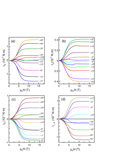
There are several notable features in Fig. 1, which will be discussed below:
(i) At high fields ( T) the torque becomes constant in field;
(ii) For the angles where the high-field torque is small, see, e.g. the curve for in Fig. 1(a) or the curve for in Fig. 1(b), the torque is nonmonotonic in the range between and 7.5 T;
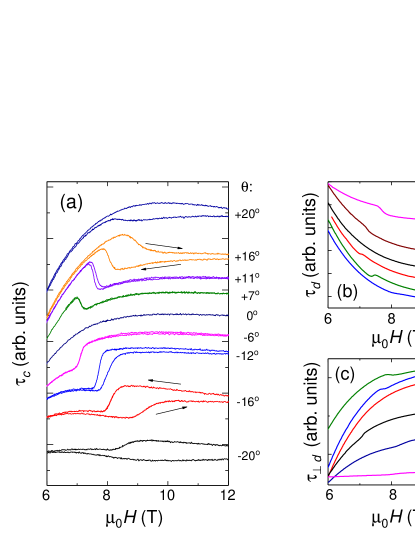
(iii) At some angles , and demonstrate a steplike feature (“kink”) at fields 7-10 T. Figure 2 shows the kinks in more details. No such kinks have been detected for at any .
Features (ii) and (iii) vanish as the temperature is increased above : the kinks disappear VyPRB11 , the field dependence becomes monotonic and gradually acquires the simple parabolic form usual for an anisotropic paramagnet at (where is the Bohr magneton and is the Boltzmann constant). Therefore, these features must be associated with the low-temperature insulating state with antiferromagnetically ordered -electron spins.
IV Discussion
The absolute values of torque in Fig. 1 are more than an order of magnitude higher than in the structurally similar but free of magnetic ions charge-transfer salt -(BEDT-TTF)2Cu[N(CN)2]Cl Pinterić M. et al. (1999). In turn, the kinks have been related to the antiferromagnetically ordered -electron spins VyPRB11 . In what follows we characterize the phenomena associated with each spin subsystem separately and address implications of their interaction.
IV.1 General expressions for the magnetic torque.
The magnetic torque is expressed as
| (1) |
where is the volume of the sample, is the sample magnetization and is the magnetic field. Let us neglect for a while the ramifications due to the sample shape (that will be discussed below) and assume the sample is a sphere. In that case
| (2) |
Consider first the high-temperature, low-field limit, . Assuming the field in the plane where and are the magnetization principal axes,
| (3) |
and the susceptibility tensor
| (4) |
one obtains the magnetization:
| (5) |
and the torque , where
| (6) |
which gives a quadratic in behavior of the torque at low fields/high temperatures, consistent with the experiment at T, see Fig. 1.
In the high-field, low-temperature regime, , the linear field dependence given by Eq. (5) is no more valid. The magnetization of a paramagnet saturates, and in a system with an isotropic -factor the effect of changing reduces to a change of the angle between the magnetization vector and the field direction. In that case the axial anisotropy follows a law CorCCR01 , so that at the torque asymptotically approaches a constant value modulated by a angular dependence. This behavior of the torque is indeed observed in our experiment, as is seen in Fig. 1 for T.
However, the nonmonotonic field dependence of torque observed in the range 2.5-7.5 T and the kink features cannot be described within the model of an anisotropic paramagnet but arise apparently due to the AF-ordered spins of the -electron subsystem, as discussed below.
IV.2 Principal axes of magnetization.
We now proceed to determining directions of the principal axes of the magnetization in -(BETS)2Mn[N(CN)2]3.
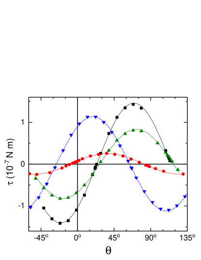
Figure 3 shows the angle-dependent torque for different rotations at K, T. The raw experimental data have been corrected for the demagnetization effect as explained in the Appendix.
As one can see in Fig. 3, all four curves follow nicely the dependence: with the paramters and listed in Table 1. For the practical reasons which will become clear below, it is more convenient to present this dependence in the form:
| (7) |
where and .
| Rotation axis | [ Nm] | [ Nm] | [ Nm] | ||
|---|---|---|---|---|---|
| 0 | 1.43 | 0.948 | |||
| 0.246 | 0.071 | 0.236 | |||
| 0.827 | 0.474 | ||||
| 1.128 | 0.888 | 0.696 |
In order to analyze the experimental results, we introduce the coordinate system , where is parallel to while and coincide with crystallographic - and -axes, respectively. The rotation axis vector is given by , where is the angle between the rotation axis and the direction. The values of for the four reported rotations are listed in Table 1.
As mentioned above, at high field the linearity between and in the form of Eq. (5) is no more valid. In order to calculate the magnetization direction in this case, instead of the susceptibility tensor we introduce tensor of the directional cosines between and vectors,
| (8) |
where , , . In that case , where is the applied field unit vector. In the limit aligns with , so that . Then, since the torque at high field is known to have a dependence where is a constant CorCCR01 , instead of using by Eq. (2) we express the torque as
| (9) |
The torque component along the rotation axis, which is measured in the experiment, is
| (10) |
For the four rotation axes used in the experiment we obtain:
| (11a) | |||
| (11b) | |||
| (11c) | |||
| (11d) |
In fact, a detailed inspection of the sample orientation for the -axis rotation has revealed that the real direction of -axis was slightly (by ) tilted from the direction of the rotation axis, and the correct value for was . Taking this into account, we obtain the corrected value for :
| (11e) |
Equating the fit parameters and listed in Table 1 to the corresponding coefficients of and in Eq. (11), one obtains the matrix:
| (12) |
The magnetization principal axes are the eigenvectors of this matrix: ; =[0, 1, 0], with for any arbitrary . The -plane of the magnetization principal axes coincides with the -plane of the crystal, which is quite reasonable since it is the mirror plane of the crystal structure. The vector is directed at from the direction in the -plane.
As it was mentioned above, at high temperatures the directions of the field where the torque vanishes, are the same as at K, T (Fig. 3). This implies that the obtained orientations of the principal axes of the magnetization are inherent to the Mn2+ spin system and do not change at the metal-insulator transition.
IV.3 Angular and Field dependence of the kinks.
As one can see in Figs. 1 and 2, the kink feature in the torque exists when the field is tilted at a moderate angle, , from the direction around the axis parallel to crystallographic directions or or to perpendicular to , but not around the -axis (). Figure 4 shows the dependence of the kink position on the polar angle for the three above-mentioned rotation axes.
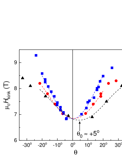
Thus, the following conditions should be satisfied in order to observe the kink:
there must be a sufficiently large field component along ;
there must be a component of the field along [010] (the b-axis);
as mentioned above, the temperature must be below .
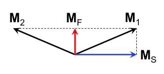
A very detailed description of the spin arrangement and field-induced spin reorientation (SR) transition in another Mott-insulating organic salt, -(BEDT-TTF)2Cu[N(CN)2]Cl, which has a structure similar to the present compound and undergoes an AF transition below K, has been given in SmPRB03 ; SmPRL04 . The key concept is that in an AF system with a low symmetry of the underlying crystal structure, the two magnetic sublattices and do not arrange strictly antiparallel along the easy axis but form a canted antiferromagnetic (CAF) order due to the Dzyaloshinskii-Moriya (DM) interaction DzJETP57 ; MorPR60 . Following the notations of Ref. 24, we introduce the ferromagnetic and staggered magnetization vectors, which are expressed through the magnetization vectors of the magnetic sublattices as: and , respectively, see Fig. 5.
The free energy of the CAF-ordered -electron spin subsystem with the sublattice magnetizations outlined in Fig. 5, in the presence of the magnetic field is composed of the Zeeman energy
| (13) |
the isotropic exchange energy
| (14) |
the anisotropic exchange energy
| (15) |
and the DM term
| (16) |
where and are, respectively, the isotropic and anisotropic exchange constants, the unit vector along the anisotropic exchange easy axis, and the DM vector. is minimized when , and when , i.e. when , ( is the magnitude of the electron spin moment in both sublattices): the spins minimize by aligning in an antiparallel orientation. is minimum when because , hence SmPRB03 ; WePB93 , and the effect of is to arrange and perpendicular to . The ultimate spin orientation is determined by a tradeoff between the four contributions to the total free energy.
The crystallographic -plane is the mirror plane in the structure of -(BETS)2Mn[N(CN)2]3. Symmetry considerations, thus, require and vectors to lie in the -plane and along the -axis. Recent calculations WiJACS15 have shown that the preferable orientation of vector is the long axis of the BETS molecule, which is in our case directed at from in the -plane. The exact direction of is currently unknown. The overall easy axis of the CAF-ordered -spin subsystem, is the compromise between the normal to vector and the direction.
Based on these considerations, one can propose a scheme of the SR transition responsible for the kink feature in the field-dependent torque. At zero field the AF sublattice moments are arranged as follows: is along the -axis and is in the -plane at some angle from , as shown in Fig. 6(a).
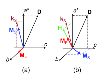
As the magnetic field is applied with a strong enough component along , so that , the orientation of along the -axis becomes unfavorable and it switches to (or maybe close to) the direction of the external field, producing an abrupt change in the magnetisation anisotropy, hence a kink in the torque signal. In turn, switches to the direction perpendicular to both and , see Fig. 6(b). Obviously, the minimum in should correspond to the external field direction along . The experimental data on the angular dependence for different rotation planes shown in Fig. 4 give a key to understanding the orientation of in the -plane. One can notice that for the rotations around the -axis and direction, is symmetric around , while for the rotation around the direction perpendicular to , which corresponds to the rotation plane closest to the -plane, the minimum in is shifted by from the direction. For this rotation plane the projection of the field, applied at polar angle , on the -plane makes an angle of with . Therefore, it is likely that is at some small angle from in the quadrant, as shown schematically in Fig. 6.
The suggested model of the AF spin arrangement explains the existence of the kinks in the field dependence of the measured torque, but does not explain why the kinks are only observed when the external field has a non-zero -axis component. For example, no kink is found for the fields exactly perpendicular to the layers, . One might doubt the existence of the SR transition at this field orientation. However, recent 13C NMR experiments confirm that it does exist VyNHMFL : in these experiments performed on a 13C-enriched crystal, the mentioned SR transition at is seen as a dramatic change in the spectrum shape right at the same values and orientations of the magnetic field at which the kink in the field-dependent torque is observed, but also at at T.
The apparent controversy can be resolved by taking into account that is the mirror plane of the crystal structure. Indeed, in this case the alignment of along the and directions is equally favorable in the absence of external field. Therefore one can expect a domain structure to be formed with equal number of the ferromagnetic moments pointing to the directions and , respectively. When an external field exceeding the critical value is applied exactly along the direction (), the SR transition does occur, but the change in the torque caused by switching of from the direction to the external field direction is compensated by the same process in the domains where the zero-field moment is pointing along . As a result no significant change in the total torque happens at such field orientation. By contrast, a non-zero -component of the applied field lifts this degeneracy, and the SR transition leads to a sizeable step in the total torque.
IV.4 Interaction between - and - spin subsystems.
So far we considered the torque features caused by the - and -spin subsystems individually. In fact, the possibility to distinguish the contributions to the torque from the two subsystems indicates the weakness of – interactions, unlike, for example in -(BETS)2FeCl4, where both - and -electron spins are antiferromagnetically ordered KonoPB05 ; ToPh05 and their individual contributions to the torque can hardly be separated.
In -(BETS)2Mn[N(CN)2]3, the – interaction between the essentially paramagnetic Mn2+ -electron spin subsystem and the AF -electron spin subsystem is apparently manifested in the nonmonotonic behavior of the torque in the intermediate field range, below T for the directions of the field close to the magnetization principal axes (Fig. 1), at which the high-field/high-temperature torque is zero.
An isolated Mn2+ spin subsystem would produce a zero torque once the field is along any principal axis of the magnetization, since in that case the magnetization vector coincides with the field direction. However, at temperatures below -electron spins form a long-range CAF order. Due to a finite ferromagnetic component, , of the ordered -electron moments, the -electron spins experience a local exchange field caused by the – interaction. This gives rise to their nonzero magnetization even in the absence of the external field . The orientation of the zero-field magnetization of Mn2+ depends on details of the – coupling and does not need to coincide with the directions of the magnetization principal axes. Therefore, in a small external field , even if it is applied along a principal axis, the magnetization of the Mn2+ subsystem is determined by the effective field , giving rise to a finite torque. As the external field (along the principal axis) increases, the Zeeman energy gradually overcomes the contribution from the – exchange, the magnetization vector turns towards the direction of , and the torque signal approaches zero. In our experiment this happens at T, as one can see from Fig. 1. Thus, the observed nonmonotonic torque behavior can be understood as a result of the – exchange in -(BETS)2Mn[N(CN)2]3. Yet other manifestations of the interaction between the two spin subsystems in this material are the violation of the Curie-Weiss behavior of the bulk magnetization KJACS08 ; VyPRB11 and a sharp increase of 1H NMR linewidth VyPRB11 ; VyJETP11 observed at .
The fact that below the AF-ordered -spin subsystem does not induce the AF order in the -electron Mn2+ spin subsystem has two origins. First is the weakness of – coupling. While the exact value of the exchange energy is unknown as yet, the absence of beats in Shubnikov-de Haas effect in the interval 11 to 29 T Kartsovnik et al. (2017) sets the upper limit for it as meV, that is times lower than in -(BETS)2FeCl4, where both subsystems order antiferromagnetically. The second factor suppressing the long-range order in the -electron subsystem is the polymer-type triangular structure of the Mn2+ lattice in the anionic layers. The dicyanamide bridges connecting Mn2+ ions favor a direct exchange interaction within the anion layers KJACS08 , which is likely to prevail the – coupling, while the triangular arrangement of Mn2+ ions frustrates their AF-type ordering.
V Summary
The anomalies found in the low-temperature magnetic torque in -(BETS)2Mn[N(CN)2]3 can be understood in terms of two spatially separated and weakly interacting spin subsystems. One subsystem is associated with -electrons of the Mn2+ ions residing in the insulating anion layers, and the other with itinerant -electrons in the conducting molecular layers, which form a long-range AF structure at the Mott-insulating transition. From the angular dependence of the high-field torque we were able to determine the directions of the principal axes of magnetization for the Mn2+ spin subsystem. The sharp kink feature observed in the field dependence of the torque in a certain angular range is interpreted as a manifestation of the spin-reorientation transition in the -electron subsystem. Based on the dependence of the kink on the field orientation, a qualitative model of the canted AF spin arrangement in this subsystem below and above the spin-orientation transition has been proposed. Finally, the weak exchange interaction between the two subsystems is manifested in the smooth nonmonotonic behavior of the torque at the field directions near the principal magnetization axes of Mn2+.
Acknowledgements
The authors gratefully acknowledge fruitful discussions with V. Ryazanov and S. Winter. The work was supported by the German Research Foundation grant KA 1652/4-1 and by the Russian Foundation for Basic Research, project No. 13-02-00350.
*
Appendix A The torque caused by the sample geometry.
Consider an isotropic paramagnet in a shape of a general ellipsoid with semi-axes , and , in the external field ,
| (17) |
where the polar angle and the azimuth angle are reckoned from and directions, respectively. Once the material is assumed isotropic, the magnetization vector is parallel to ,
| (18) |
and saturates to a constant value at high fields. The demagnetizing field is:
| (19) |
where the demagnetizing factor
| (20) |
The torque arising from the sample geometry is
| (21) |
The projection of the torque on the field rotation axis, , is:
| (22) |
As mentioned in Sec. II, the sample dimensions are 0.08, 0.7 and 0.3 mm along , and crystallographic directions, respectively. Taking these values as the ellipsoid semi-axes, and using the approach of Refs. 33; 34 one obtains the demagnetizing factors , and . For one can use the maximum value A/m of the saturated paramagnet with , , which seems to be a reasonable estimation according to the dc magnetometry data VyPRB11 . Then for the rotation axes along (), [001] (), (), and the perpendicular to () Eq. 22 gives (in units Nm)
| (23a) |
| (23b) |
| (23c) |
| (23d) |
References
- (1) N. D. Kushch, E. B. Yagubskii, M. V. Kartsovnik, L. I. Buravov, A. D. Dubrovskii, A. N. Chekhlov, and W. Biberacher, J. Am. Chem. Soc. 130, 7238 (2008).
- (2) V. N. Zverev, M. V. Kartsovnik, W. Biberacher, S. S. Khasanov, R. P. Shibaeva, L. Ouahab, L. Toupet, N. D. Kushch, E. B. Yagubskii, and E. Canadell, Phys. Rev. B 82, 155123 (2010).
- (3) H. Kobayashi, H. Cui and A. Kobayashi, Chem. Rev. 104, 5265 (2004).
- Kobayashi et al. (1996) H. Kobayashi, H. Tomita, T. Naito, A. Kobayashi, F. Sakai, T. Watanabe, and P. Cassoux, J. Am. Chem. Soc. 118, 368 (1996) .
- Akutsu et al. (1998) H. Akutsu, K. Kato, E. Ojima, H. Kobayashi, H. Tanaka, A. Kobayashi, and P. Cassoux, Phys. Rev. B 58, 9294 (1998).
- (6) H. Fujiwara, E. Fujiwara, Y. Nakazawa, B. Zh. Narymbetov, K. Kato, H. Kobayashi, A. Kobayashi, M. Tokumoto, P. Cassoux, J. Am. Chem. Soc. 123, 306 (2001).
- (7) L. Brossard, R. Clerac, C. Coulon, M. Tokumoto, T. Ziman, D. K. Petrov, V. N. Laukhin, M. J. Naughton, A. Audouard, F. Goze, A. Kobayashi, H. Kobayashi, and P. Cassoux, Eur. Phys. J. B 1, 439 (1998).
- Uji et al. (2001) S. Uji, H. Shinagawa, T. Terashima, T. Yakabe, Y. Terai, M. Tokumoto, A. Kobayashi, H. Tanaka, and H. Kobayashi, Nature 410, 908 (2001).
- Balicas et al. (2001) L. Balicas, J. S. Brooks, K. Storr, S. Uji, M. Tokumoto, H. Tanaka, H. Kobayashi, A. Kobayashi, V. Barzykin, and L. P. Gor’kov, Phys. Rev. Lett. 87, 067002 (2001).
- Konoike et al. (2005) T. Konoike, S. Uji, T. Terashima, M. Nishimura, S. Yasuzuka, K. Enomoto, H. Fujiwara, E. Fujiwara, B. Zhang, and H. Kobayashi, Phys. Rev. B 72, 094517 (2005).
- Konoike et al. (2006) T. Konoike, S. Uji, T. Terashima, M. Nishimura, T. Yamaguchi, K. Enomoto, H. Fujiwara, B. Zhang, and H. Kobayashi, J. Low Temp. Phys. 142, 531 (2006).
- Kunz et al. (2016) M. Kunz, W. Biberacher, N. D. Kushch, A. Miyazaki, and M. V. Kartsovnik, Phys. Rev. B 94, 205104 (2016).
- Konoike et al. (2004) T. Konoike, S. Uji, T. Terashima, M. Nishimura, S. Yasuzuka, K. Enomoto, H. Fujiwara, B. Zhang, and H. Kobayashi, Phys. Rev. B 70, 094514 (2004).
- (14) H. Fujiwara, H. Kobayashi, E. Fujiwara, and A. Kobayashi, J. Am. Chem. Soc. 124, 6816 (2002).
- Kartsovnik et al. (2016) M. Kartsovnik, M. Kunz, L. Schaidhammer, F. Kollmannsberger, W. Biberacher, N. Kushch, A. Miyazaki, and H. Fujiwara, J. Supercond. Nov. Magn. 29, 3075 (2016).
- (16) O. M. Vyaselev, M. V. Kartsovnik, N. D. Kushch, and E. B. Yagubskii, JETP Lett. 95, 565 (2012) [Pisma v ZhETF 95, 961 (2012)].
- (17) O. M. Vyaselev, R. Kato, H. M. Yamamoto, M. Kobayashi, L. V. Zorina, S. V. Simonov, N. D. Kushch, and E. B. Yagubskii, Crystals 2, 224 (2012).
- (18) O. M. Vyaselev, M. V. Kartsovnik, W. Biberacher, L. V. Zorina, N. D. Kushch, and E. B. Yagubskii, Phys. Rev. B 83, 094425 (2011).
- (19) O. M. Vyaselev, N. D. Kushch, and E. B. Yagubskii, JETP 113, 835 (2012) [Zh. Eksp. Teor. Fiz. 140, 961 (2012)].
- (20) P. Christ, W. Biberacher, H. Müller, and K. Andres, Solid State Commun. 91, 451 (1994).
- Pinterić M. et al. (1999) M. Pinterić, M. Miljak, N. Biškup, O. Milat, I. Aviani, S. Tomić, D. Schweitzer, W. Strunz, and I. Heinen, Eur. Phys. J. B 11, 217 (1999).
- (22) A. Cornia, D. Gatteschi, and R. Sessoli, Coord. Chem. Rev. 219–221, 573 (2001).
- (23) D. F. Smith, S. M. De Soto, C. P. Slichter, J. A. Schlueter, A. M. Kini, and R. G. Daugherty, Phys. Rev. B 68, 024512 (2003).
- (24) D. F. Smith, C. P. Slichter, J. A. Schlueter, A. M. Kini, and R. G. Daugherty, Phys. Rev. Lett. 93, 167002 (2004).
- (25) I. E. Dzialoshinskii, JETP 5, 1259 (1957).
- (26) T. Moriya, Phys. Rev. 120, 91 (1960).
- (27) U. Welp, S. Fleshler, W. K. Kwok, G. W. Crabtree, K. D. Carlson, H. H. Wang, U. Geiser, J. M. Williams, and V. M. Hitsman, Physica B 186–188, 1065 (1993).
- (28) S. M. Winter, S. Hill, and R. T. Oakley, J. Am. Chem. Soc. 137, 3720 (2015).
- (29) O. M. Vyaselev et al., unpublished.
- (30) T. Konoike, S. Uji, M. Nishimura, K. Enomoto, H. Fujiwara, B. Zhang, and H. Kobayashi, Physica B 359- 361, 457 (2005).
- (31) M. Tokumoto, H. Tanaka, T. Otsuka, H. Kobayashi, and A. Kobayashi, Polyhedron 24, 2793 (2005).
- Kartsovnik et al. (2017) M. V. Kartsovnik, V. N. Zverev, W. Biberacher, S. V. Simonov, I. Sheikin, N. D. Kushch, and E. B. Yagubskii, Low Temp. Phys. 43, 239 (2017).
- (33) J. A. Osborn, Phys. Rev. 67, 351 (1945).
- (34) M. Beleggia, M. De Graef, and Y. Millev, Phil. Mag. 86, 2451 (2006).