Electron transport in magnetic tunnel junctions - a theoretical study of lattice and continuum models
Abstract
Magnetic tunnel junctions comprising of an insulator sandwiched between two ferromagnetic films are the simplest spintronic devices. Theoretically, these can be modeled by a metallic Hamiltonian in both the lattice and the continuum with an addition of Zeeman field. We calculate conductance at arbitrary orientations of the easy axes of the two ferromagnets. When mapped, the lattice and the continuum models show a discrepancy in conductance in the limit of a large Zeeman field. We resolve the discrepancy by modeling the continuum theory in an appropriate way.
I Introduction
Magnetic tunnel junctions are basic building blocks of spintronic devices fabian . The experiments by Moodera et.al and Miyazaki et.al moodera95 ; miyazaki (1995) on magnetic tunnel junctions demonstrated a large tunnel magnetoresistance (TMR) at room temperature and resulted in upsurge of activities in this field. Parkin et.al parkin used MgO as a tunnel barrier and enhanced the TMR to nearly 200 %. A more recent experiment ikeda (2008) reported a much higher value of TMR (604 %) at room temperature. Theoretically, magnetic tunnel junctions have been modeled even recently with the objective of studying the electron transport across the junctions pasanai15 ; sun ; zheng ; prl . Other apsects of the continuum model we study in this work has been earlier addressed by Pasanai pasanai15 in a one dimensional system.
In experimental systems, the junction can be tuned between ON and OFF states by an externally applied magnetic field moodera95 ; ikeda . The ON state is when the spins in the two FM’s are parallel and OFF state is when the two spins are anti-parallel. In the ON state, the current between the two FM’s due to an applied bias is large and in the OFF state, it is small. However, theoretically the two FM’s can be in a configuration that is more general than ON and OFF, where the spins in the two ferromagnets are aligned at a relative angle (with ). We shall use this as a theoretical tool to understand the modeling of tunnel junctions. The experimental realizations generally correspond to the cases (ON) and (OFF).
In Sec. II, we discuss the continuum and lattice models that describe a ferromagnet, followed by an outline of a mapping from continuum to lattice model. In Sec. III, we discuss the modeling of the tunnel junction. In Sec. IV, we calculate conductance. In Sec. V, we point to the discrepancy between the two models and resolve it. In Sec. VI, we summarize and end with concluding remarks.
II Models of ferromagnet
II.1 Continuum model
In continuum, an FM can be modeled by the Hamiltonian
| (1) |
where for denote the Pauli spin matrices, the parameters denote the effective mass of electrons, chemical potential and the Zeeman energy respectively. The dispersions for up- and down- spins are respectively given by and . By convention, Fermi energy is at zero and whenever a bias is applied, the bias window is placed at the Fermi energy. It is easy to see that the band-bottom for up- and down- spins are at the energies and () respectively.


II.2 Lattice model
The ferromagnet can also be modeled by a lattice Hamiltonian on a cubic lattice-
| (2) |
where and is the second quantized annihilation operator for the spin- electron at site-, and takes on unit vectors along -directions. The parameters are the hopping strength, chemical potential and the Zeeman energy respectively for the lattice model. In certain limits, these parameters can be mapped on to the parameters in the continuum model. The dispersion for the up-spin and the down-spin electrons in the lattice model take the form: and . The parameter is the lattice spacing.
II.3 Mapping between the two models of ferromagnet
A schematic of the dispersions for the lattice and the continuum is shown in Fig. 1. We work in the range of parameters: (i) in the continuum and (ii) and in the lattice. The dispersion relation for a continuum model is isotropic while that for the lattice model is not isotropic except very close to the band bottom. We now discuss on how to map from the continuum model to a lattice model. The lattice model is an effective model and may not depict the underlying lattice structure of the material, but agrees with the continuum model at low energies. Starting from a continuum model, we set the Zeeman energy in the lattice model to be the same (). The condition ensures that the band bottoms of the two models are aligned. The lattice dispersion has the same form as in the continuum in the limit when , which can be seen by Taylor expanding the lattice dispersion around and keeping terms upto second order in . This gives us: . We choose the lattice constant by demanding that in the bias window, the binomial expansion of the lattice dispersion is a good approximation: . Once is chosen to satisfy the above condition, .
When is large enough so that [same as ], the down spin branch of the dispersion does not lie in the bias-window and the FM has 100% polarization with only up-spin channel being occupied at zero temperature. We call such a ferromagnet a “pure FM”. At a finite temperature, the down-spin channel has a small but finite occupation and the polarization is less than 100% in such pure FM’s. The exact value of polarization at a given temperature depends on how large is and decreases monotonically with . We also introduce the limit , in which we call the ferromagnet a “perfect FM” since the polarization even at a finite temperature remains at 100%.
III Junction between two ferromagnets
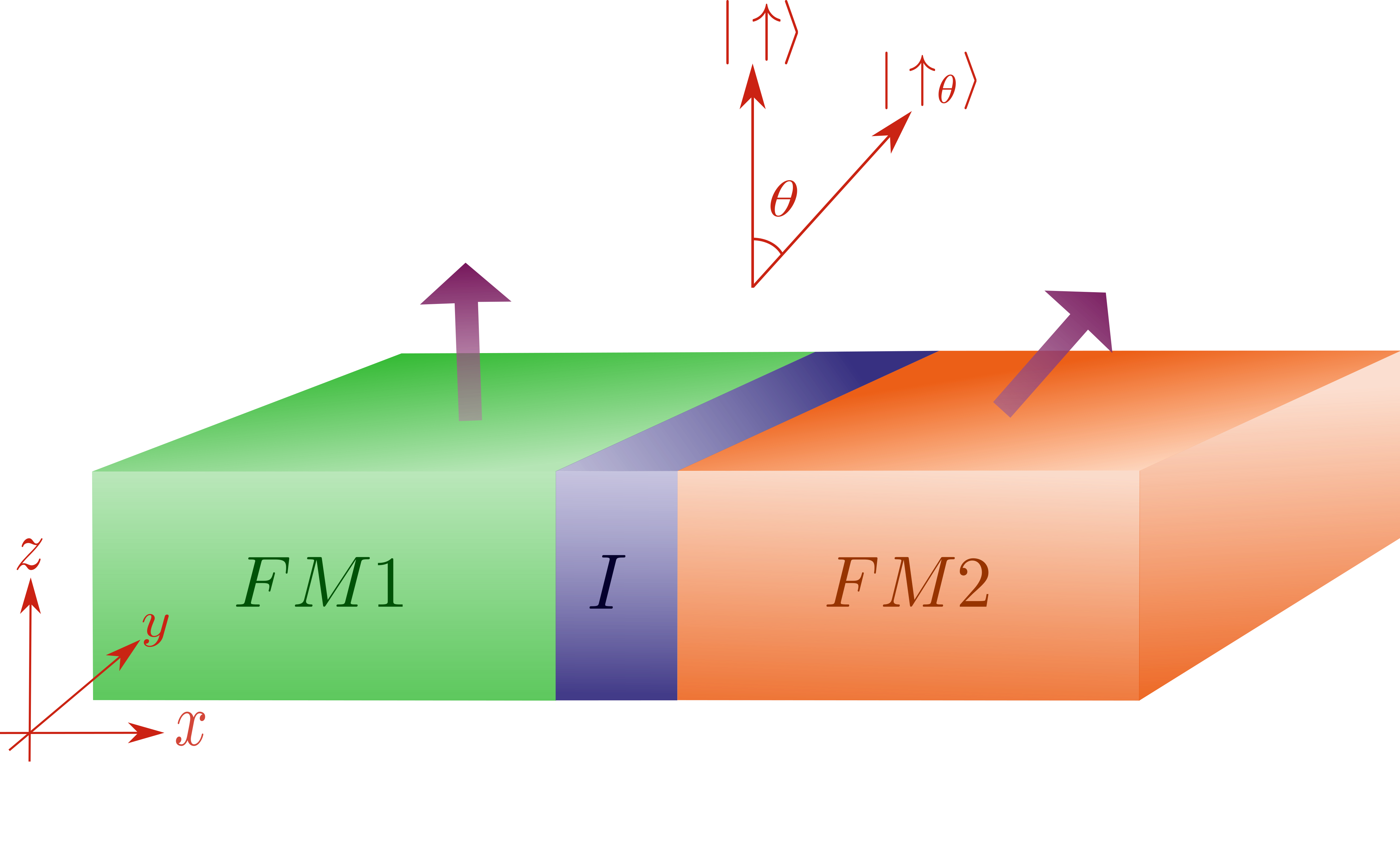
In continuum, a junction between two ferromagnets is typically described by respective Hamiltonians on either sides of with boundary condition (BC) applied to the wavefunction at . A junction between FM’s pointing in two directions which are at angle is modeled when the Hamiltonian on left is given by Eq. (1) and the Hamiltonian on the right is given by Eq. (1), where is replaced by . The wavefunctions on either sides of the junction are equal and their derivatives differ by a quantity proportional to the amplitude of the wavefunction at the junction-point:
| (3) |
where parametrizes the transparency of the junction. The limits and correspond to fully transparent and fully opaque junctions.
In the lattice model, the junction is typically characterized by a hopping between two sides of the lattices governed by different Hamiltonians and the BC does not appear. The information about the BC (of the continuum model) is carried by the hopping element in the -direction. The Hamiltonian on the left is given by eq. (2) where and takes integer values such that . The Hamiltonian on the right is given by eq. (2) where and take integer values such that , and replaced by like in the continuum. The full Hamiltonian is:
| (4) | |||||
and run over all integers.
We shall now specialize to the perfect ferromagnet limit, where . Physically, this makes sense when the for the ferromagnet is much larger than all other energy scales in the problem. Also, this makes the calculations much simpler since one of the two spin channels tends to be absent.
IV Transport Calculations in continuum and lattice models
We follow Landauer-Büttiker scattering approach landau-butti ; lb4 ; landau-butti2 ; landau-butti3 ; dattabook to calculate conductance in continuum and lattice models. We write down a wavefunction which has incident and scattered parts and solve for the scattering coefficients. Since this is a three dimensional system, there are two angles of incidence and the total current at a given bias is calculated by integrating the currents over the full range of angles of incidence with appropriate factors. In the scattering theory calculation for tunnel junctions, an electron is incident at the junction and scattering amplitudes for scattering into different channels is calculated. Let and be the angles made by the incident electron having momentum such that . is the angle made by the incident electron with -axis, while is the angle made by the projection of the momentum onto the plane with -axis. Due to translational invariance along - and - directions, the momenta and are good quantum numbers.
In continuum, the wavefunction of an electron incident on the tunnel junction at an energy from left lead will look like where,
| (5) | |||||
where and the kets denote the spinors: , , and . Here, the wavevectors in the down-spin channels ( for , and for ) are absent since we have taken the limit of pure ferromagnet. To solve for the scattering amplitudes and , we employ the boundary conditions discussed in Eq (3). It is easy to see from here that for any nonzero , and hence the conductance of the junction is zero. This comes as a surprise. At , the problem becomes that of a spinless tunnel junction the conductance of which is dictated by the barrier strength .
In the lattice model, the wavefunction of an electron incident on the tunnel junction at an energy from the left lead takes the form , where , where is discrete Heaviside step function and the kets retain the identity assigned in previous paragraph. This just states that electrons can point only along the easy axis and the easy axes of electrons on either sides of the junction differ by an angle . Further, the wavefunction takes the form:
| (6) | |||||
where . We choose such that the lattice dispersion can be approximated to be a quadratic dispersion near the band bottom, as discussed in section II.3. Note that so chosen is negative. The equation connecting the wavefunctions on either sides of the junction obtained from lattice Hamiltonian eq. (4), reduces to the following equations in the limit of perfect ferromagnet:
| (7) |
where . The term in eq. (7) proportional to can be understood as follows- since an electron on site does not flip spin while hopping on to , where the eigenspinor is , the overlap is . Solving for the scattering amplitudes using eq. (7), we get
| (8) |
and the differential conductance is given by
| (9) | |||||
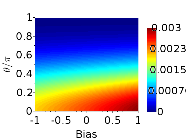
and is the area of cross section of the tunnel junction. The energy dependent factor in the conductance reflects the density of states in three dimensional ferromagnet. In Fig. 3, we show the result for differential conductance as a function of the angle and the bias.
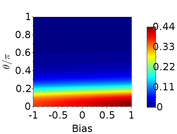
V Discrepancy and its resolution
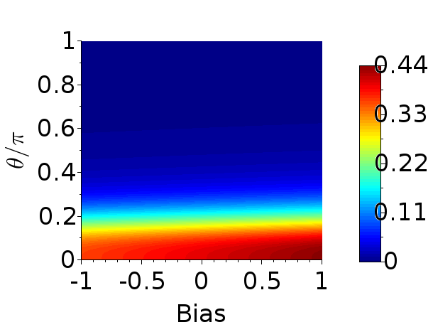
In the last section (sec. IV) we demonstrated that the lattice and the continuum models of the junction give highly distinct results for conductance of the magnetic tunnel junction made from perfect FM’s. In the lattice model, the conductance is exactly zero only when , while in the continuum model, the conductance is zero whenever . At this point, the results from lattice model look more reasonable. To resolve the puzzle, we now take lattice model as the starting point of analysis. The physical meaning of the hopping term in the Hamiltonian [eq. (4)] is that the atomic wavefunctions on the two lattice sites overlap and the overlap is proportional to . In contrast, the wavefunctions on the two sides of the junction in the continuum model cannot overlap with each other whenever since the limit does not allow any nonzero spin-component in a direction different from the easy axis. However, a region of finite length can be introduced between the two ferromagnets in the continuum model where both spin channels are allowed and the two wavefunctions can overlap. We show that introduction of such a region resolves the disagreement between the two models. The region in between can be modeled to have a length and a barrier that reflects the hopping element . The barrier in the region is isotropic in the spin space and the boundary conditions at and are continuity of wavefunction and its derivative . The limits and correspond to and respectively.
The wavefunction of an electron incident on the tunnel junction at an energy from left lead will look like where,
| (10) | |||||
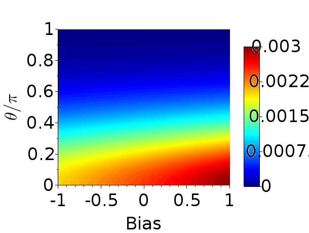
Continuity of at gives four equations while continuity of at and continuity of at totally give six equations to be solved for six scattering amplitudes. We are interested in , since conductance can be calculated from it using eq. (9). We numerically compute for each , and integrate over as shown in eq. (9) to get conductance for a given bias . The result for continuum model with an insulating layer in between the two FM’s is presented in Fig. 4. The parameters for the two models have been chosen such that the final result looks the same and we have demonstrated this in the fully transparent and weakly transmitting limits. The results show a remarkable similarity both qualitatively and quantitatively.
VI Summary and discussion
To summarize, we started with models of ferromagnets and using these as building blocks, studied magnetic tunnel junctions in both continuum and lattice models. In the limit of perfect FM, the discrepancy between the continuum and the lattice models first came as a surprise. However, the results from the lattice model calculations appeared more convincing. We then resolved the discrepancy by appropriate modeling of the system in continuum model. In other words, given a magnetic tunnel junction described by a lattice model, we found the corresponding continuum model.
The central result of our work is that magnetic tunnel junctions in the continuum model comprise of a nonmagnetic insulating layer sandwiched between the two ferromagnets. Absence of such a nonmagnetic region gives rise to unphysical results. However, in a lattice model, there is no need for a nonmagnetic layer for magnetic tunnel junction.
In this work we have primarily focused on perfect ferromagnets, where no modes in the direction other than spin easy axis is allowed. It will be interesting to investigate the lattice and continuum models in the pure ferromagnets where the wavefunction in the direction opposite to that of spin easy axis decays exponentially away from the junction. In junctions comprising of pure FM’s, the non-magnetic region may not be required in modeling since the wavefunctions opposite to spin easy axis can overlap in the region close to the junction. Further, connection to experimental systems is another future direction.
Acknowledgements
We thank Diptiman Sen for stimulating discussions. DS thanks DST-INSPIRE, Govt. of India for PhD fellowship (No. DST/INSPIRE Fellowship/2013/742). AS thanks DST under grant number DSTO1597 and DST-INSPIRE Faculty award scheme under award number IFA17-PH190.
References
- (1)
- (2) I. Zutic, J. Fabian, and S. Das Sarma, “Spintronics: Fundamentals and applications”, Rev. Mod. Phys. 76, 323 (2004).
- (3) J. S. Moodera, L. R. Kinder, T. M. Wong, and R. Meservey, “Large Magnetoresistance at Room Temperature in Ferromagnetic Thin Film Tunnel Junctions”, Phys. Rev. Lett. 74 3273–3276 (1995).
- (4) T. Miyazaki, N. Tezuka, “Giant Magnetic Tunneling Effect in Fe/Al2O3/Fe Junction”, J. Magn. Magn. Mater. 139, L231 – L234 (1995).
- (5) S. S. P. Parkin, C. Kaiser, A. Panchula, P. M. Rice, B. Hughes, M. Samant and S.-H. Yang, “ Giant tunnelling magnetoresistance at room temperature with MgO (100) tunnel barriers”, Nat. Mater. 3, 862 - 867 (2004).
- (6) S. Ikeda, J. Hayakawa, Y. Ashizawa, Y.M. Lee, K. Miura, H. Hasegawa, M. Tsunoda, F. Matsukura and H. Ohno “Tunnel magnetoresistance of 604% at 300 K by suppression of Ta diffu- sion in CoFeB/MgO/CoFeB pseudo-spin-valves annealed at high temperature”, Appl. Phys. Lett. 93 (8): 082508 (2008).
- (7) K. Pasanai, “Similarities of coherent tunneling spectroscopy of ferromagnet/ferromagnet junction within two interface models: Delta potential and finite width model”, J. Magn. Magn. Mater. 401, 463-471 (2015).
- (8) J. C. Slonczewski, J. Z. Sun, “Theory of voltage-driven current and torque in magnetic tunnel junctions”, J. Magn. Magn. Mater. 310, 169-175, (2007).
- (9) Z-C. Wang, G. Su, Q-R. Zheng, and B-H. Zhao, “Spin tunneling in ferromagnet-insulator-ferromagnet junctions”, Phys. Lett. A 277, 47-55 (2000).
- (10) Ph. Mavropoulos, N. Papanikolaou, and P. H. Dederichs , “Complex Band Structure and Tunneling through Ferromagnet /Insulator /Ferromagnet Junctions”, Phys. Rev. Lett. 85, 1088-1091 (2000).
- (11) S. Datta and B. Das, “Electronic analog of the electro‐optic modulator ”, Appl. Phys. Lett. 56, 665 (1990).
- (12) R. Landauer, “Spatial Variation of Currents and Fields Due to Localized Scatterers in Metallic Conduction”, IBM J. Res. Dev. 1, 223 (1957).
- (13) R. Landauer, “Electrical resistance of disordered one-dimensional lattices ”, Philos. Mag. 21, 863 (1970)
- (14) M. Büttiker, Y. Imry, R. Landauer, and S. Pinhas, “Generalized many-channel conductance formula with application to small rings”, Phys. Rev. B 31, 6207 (1985)
- (15) M. Büttiker, “Four-Terminal Phase-Coherent Conductance”, Phys. Rev. Lett. 57, 1761 (1986)
- (16) S. Datta, Electronic Transport in Mesoscopic Systems (Cambridge University Press, Cambridge, 1995).