Temperature-Dependent Cycloidal Magnetic Structure in GdRu2Al10 Studied by Resonant X-ray Diffraction
Abstract
We have performed resonant X-ray diffraction experiments on the antiferromagnet GdRu2Al10 and have clarified that the magnetic structure in the ordered state is cycloidal with the moments lying in the plane and propagating along the axis. The propagation vector shows a similar temperature dependence to the magnetic order parameter, which can be interpreted as being associated with the gap opening in the conduction band and the resultant change in the magnetic exchange interaction. Although the state of Gd is almost isotropic, the moments show slight preferential ordering along the axis. The axis component in the cycloid develops with decreasing temperature through a tiny transition in the ordered phase. We also show that the scattering involves the - process, which is forbidden in normal - resonance of magnetic dipole origin. We discuss the possibility of the - resonance originating from a toroidal moment due to the lack of inversion symmetry at the Gd site. The spin-flop transition in a magnetic field is also described in detail.
1 Introduction
Hybridization between localized and itinerant electrons gives rise to a rich variety of electronic states through competition between the Kondo effect and the Ruderman–Kittel–Kasuya–Yosida (RKKY) magnetic exchange interaction.[1] In -electron systems, the former leads to a nonmagnetic heavy-fermion state, or in some cases, a Kondo semiconducting state, whereas the latter preferentially leads to a magnetic ordered state. Recently, a new type of Kondo semiconductor system, CeAl10 (=Ru and Os), has been attracting continuous interest because of its unconventional nature of a long-range magnetic order coexisting with the Kondo effect due to strong - hybridization.[2, 3, 4, 5, 6, 7, 8, 9, 10, 11] The most prominent feature is the high transition temperatures; K for CeRu2Al10 and 28.7 K for CeOs2Al10, which are higher than K for GdRu2Al10 and cannot be understood as being caused by the normal RKKY exchange interaction. In spite of the extensive studies, the true mechanism of the ordering phenomenon has not yet been clarified.
CeAl10 is also anomalous from the viewpoint of its magnetic propagation vector. The magnetic moments in CeAl10 order along the axis with the propagation vector .[12, 13, 14] In isostructural NdFe2Al10 and SmRu2Al10, on the other hand, the magnetic structure is described by and its third harmonic of , reflecting the squaring up.[15, 16] The high-temperature phase of SmRu2Al10 is an incommensurate phase with . There is also a case of as in TbRu2Al10.[17] Therefore, seems to be a common propagation vector corresponding to the RKKY interaction in the Al10 series of compounds. Although for =Ce reflects some common characteristic of this crystal structure in the sense that lies along the axis, the slight difference from other isostructural compounds may have some association with the - hybridization effect.
GdRu2Al10 shows an antiferromagnetic order at K, followed by another weak transition at K.[18] The magnetic susceptibility and magnetization of GdRu2Al10 can well be explained by a mean-field model calculation and can be understood as a simple antiferromagnet of almost isotropic Gd3+ with . Since shows a cusp anomaly for and , the ordered moments are expected to be in the plane. This is also consistent with the spin-flop transition observed for and . However, the actual magnetic structure has not yet been clarified.
The purpose of the present study is to investigate the magnetic structure of GdRu2Al10 by resonant X-ray diffraction. Since Gd is a strong neutron-absorbing element, the magnetic structure has not been determined yet by neutron diffraction. Resonant X-ray diffraction is more suitable in this study. The high space resolution obtained by using a synchrotron X-ray beam is also an advantage, which has been utilized in this study to measure the shift of the peak position with temperature.
2 Experiment
Single crystals of GdRu2Al10 were prepared by an Al flux method. The magnetic susceptibility and magnetization of this sample have already been reported in Ref. \citenSera13a. A resonant X-ray diffraction experiment was performed at BL-3A of the Photon Factory, High Energy Accelerator Research Organization (KEK). Two samples were prepared for the experiment, one with a (100) surface and the other with a (010) surface, which were both mirror-polished. A magnetic field was applied using a vertical field 8 T superconducting cryomagnet. We used X-ray energies near the absorption edge of Gd. Polarization analysis was performed using a Cu-220 reflection, where the scattering angle was at 7.246 keV. We also used a diamond phase retarder system installed at BL-3A, which enabled us to tune the horizontally polarized incident beam to a circularly polarized beam.
3 Results and Analysis
3.1 Temperature-dependent propagation vector
In the reciprocal lattice scan at the lowest temperature of 2 K, we found clear diffraction peaks at incommensurate positions corresponding to , where and is the reciprocal lattice vector of the fundamental lattice. No higher harmonic peaks were detected, indicating that the magnetic structure is described by a single component. In Fig. 1, we show the energy dependence of the Bragg peak at . The intensity shows a resonant enhancement at 7.248 keV, corresponding to the - () resonance. No significant change in the fundamental lattice reflections was detected within the accuracy of the present experiment, indicating that the magnetostriction, i.e., the coupling with the lattice, is very small.
The very high count rate of 6000 cps reflects the large ordered moment of Gd3+ with , resulting in a large exchange splitting in the state of Gd. This enabled us, as described in the following, to investigate the scattering process in detail by performing polarization analysis and by using a phase retarder device, which both lead to a significant reduction of the count rate but nevertheless a reasonable signal intensity remains.
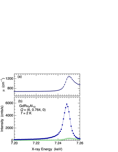
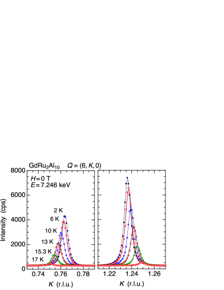
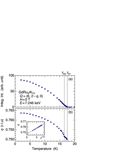
Figure 2 shows the reciprocal scans of the resonance intensity along the line at several temperatures. Since this peak disappears above K, the scattering can be ascribed to magnetic origin, i.e., the resonance is associated with the exchange splitting in the state of Gd, which is induced by the magnetic moment in the orbital.[19] In addition, it is intriguing that the peak position continuously shifts with the temperature. Since the positions of the Bragg peaks of (6, 0, 0) and (6, 2, 0) do not change at all, this shift in the magnetic Bragg peak directly shows that the periodicity of the incommensurate magnetic structure changes with the temperature. The temperature dependences of the integrated intensity and the value obtained from this measurement are shown in Fig. 3. Interestingly, the value seems to start from nearly 0.75 just below K. Note that is a value commonly observed in other RAl10 compounds such as NdFe2Al10 and SmRu2Al10.[15, 16] The similar result for GdRu2Al10 seems to show that is the fundamental propagation vector of the RKKY interaction in the RAl10 system. It is also noteworthy that the temperature dependence of the value is very similar to that of the order parameter. As shown in the inset of Fig. 3(b), it is proportional to the square root of the intensity, reflecting the magnitude of the magnetic moment. From this plot, we see that the value obtained from the extrapolation to zero intensity is , which is not exactly the commensurate value of 0.75.
3.2 Cycloidal magnetic structure
3.2.1 Magnetic structure model
There are two atomic positions of Gd at the site of the space group: Gd-1 at and Gd-2 at , where .[20, 21] In the present single- magnetic structure, the magnetic moments, and of Gd-1 and Gd-2, on the th lattice point at and ( are integers) are generally expressed as
| (1) | ||||
| (2) |
where and are the magnetic amplitude vectors of Gd-1 and Gd-2, respectively. In the present case of GdRu2Al10, since it is expected from the and behaviors that the moments are ordered in the plane, it is also expected that and can be written using the and axis components as and , where and represent the unit vectors along the and axes, respectively, the phase difference between the and axis components, the phase difference between the moments of Gd-1 and Gd-2, and and the amplitudes of the moments of Gd-1 and Gd-2, respectively. These expressions for the magnetic structure are reduced to the following:
| (3) | ||||
| (4) |
Since is along the axis, this structure generally represents a cycloidal magnetic structure. When , it describes a perfect cycloid in which the adjacent moments have a fixed angle. When , the moments of Gd-1 and Gd-2 at the nearest-neighbor positions are antiferromagnetically coupled.
3.2.2 Polarization analysis
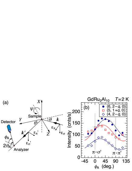
To examine the magnetic structure, we have performed a polarization analysis measurement at 2 K for three peaks in the plane. The scattering geometry and the results are shown in Fig. 4. The solid lines are the calculations using the following expression for the - scattering amplitude of magnetic dipole origin:
| (5) |
where represents the Gd site and is the scattering vector. Note that is expressed as the scalar product of the geometrical factor for the rank-1 - resonance, , and the magnetic structure factor (rank-1 tensor).[22] We assumed an equal amplitude of , an antiferromagnetic coupling of , and a slightly modified cycloid of . If we assume a perfect cycloid of , we obtain almost flat dependence, which clearly disagrees with the data exhibiting a significant oscillation. If we assume a collinear structure with , the intensity should vanish at some , which also disagrees with the data. From these results, we can conclude that the magnetic structure of GdRu2Al10 is a modified cycloid. Although the assumption of is not validated here, it will be described later.
3.2.3 Measurement using circularly polarized X-rays
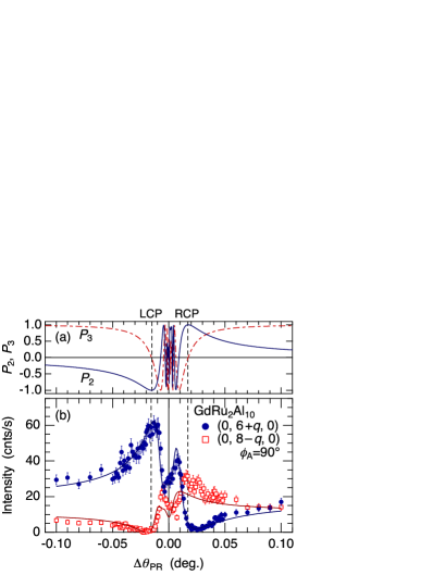
Another experimental result providing direct evidence for the cycloidal structure is shown in Fig. 5. In this measurement, we inserted a diamond phase retarder in the incident beam and tuned the incident polarization state. By rotating the angle of the phase retarder around the (1, 1, 1) Bragg angle , where the scattering plane is tilted by , a phase difference arises between the and components in the transmitted beam, which is proportional to . This allows us to tune the incident linear polarization to left-handed circular polarization (LCP) and right-handed circular polarization (RCP) by changing . The polarization state of the incident beam as a function of is shown in Fig. 5(a) using the Stokes parameters ( for RCP and for LCP) and ( for and for ). Since we used the vertical scattering plane configuration in this measurement [the configuration in Fig. 4(a) is rotated by around the axis], the incident linear polarization is when is large. ( for and for linear polarization) is zero in this setup.
As clearly demonstrated in Fig. 5(b), the magnetic Bragg peaks at and exhibit the opposite dependence on . That is, the peak intensity at is strong for LCP but weak for RCP, whereas the relation becomes opposite at . This is theoretically explained by assuming the cycloidal structure. For simplicity, if we assume a perfect cycloid with ( helicity), the - scattering amplitude matrix for a peak, where is parallel to the propagation vector of the cycloid, is written as
| (6) |
Here, is responsible for the scattering cross section proportional to . The intensity for an incident X-ray with and with analyzer conditions of and is calculated to be
| (7) |
When the helicity changes, or when , the and signs are interchanged. Although the expression is slightly modified for , the basic mechanism of the asymmetric intensity is the same. The solid lines in Fig. 5(b) are the calculated curves for the proposed magnetic structure of the modified cycloid.
This experimental result shows that the helicity of the cycloid, i.e., the sign of , is uniquely determined in the sample without a formation of domains at least within the range of the beam size of mm2 at the surface. Since the crystal space group has an inversion symmetry and mirror planes, the two cycloids with and helicity have equal energy and should form domains. If the two domains are mixed, the result in Fig. 5(b) should exhibit a more symmetric curve. We consider that this is an accidental result caused by some surface strains due to polishing or by some external strain from the varnish used to glue the sample. Note that the following experimental results were also obtained in the single-domain state. This provides us with a valuable opportunity to extract detailed information.
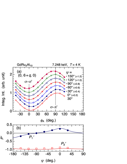
3.3 Local noncentrosymmetry and toroidal moment
Figure 6(a) shows scans performed at several azimuthal angles using a four-circle diffractometer with a vertical scattering plane. The incident polarization is in this configuration. The results in Fig. 6(a) show that the scattering is mostly -, which is a reasonable result for the - resonance of magnetic dipole origin. However, the minimum and maximum positions of the intensity are slightly shifted from and , respectively. If there is no - scattering, the intensity should have a minimum at . This result shows that there is some - intensity, which is forbidden in the - resonance of magnetic origin because .
From the scans, we can extract the linear polarization states and of the scattered X-ray using the following expressions. The intensity at the detector after the analyzer crystal is expressed as
| (8) |
where represents the scattering cross section at the sample and is the Stokes parameter for the analyzer:
| (9) |
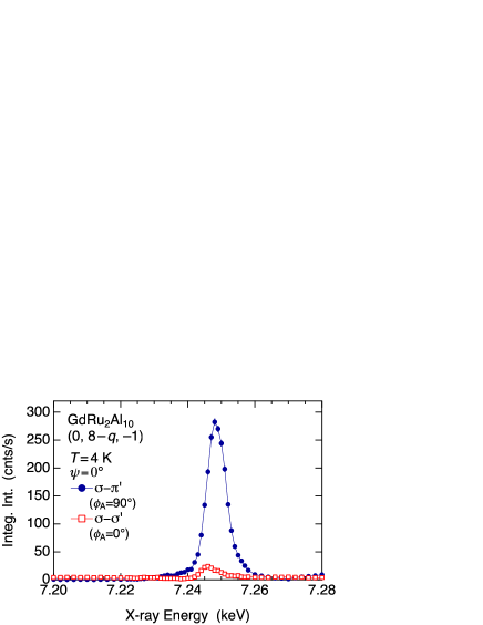
The result of the analysis is shown in Fig. 6(b). This shows not only that is constantly close to , indicating that the scattering is mostly - in the whole region, but also that exists, which is associated with the appearance of - scattering. The existence of - scattering is also directly demonstrated in Fig. 7 by an energy scan.
One possibility for the origin of the - scattering is an - resonance through the transition. The scattering amplitude for an - resonance of magnetic dipole origin (rank-1) is obtained by replacing the geometrical factor in Eq. (5) with that of -: .[23] By considering that the - scattering interferes with the - scattering, we can explain the appearance of - scattering and the dependence of and shown in Fig. 6(b). However, the energy position of the resonant peak for - is only 2 eV below that for -, suggesting that the resonance is mainly of character. Since an - resonance for the edge of a rare-earth atom typically occurs approximately 10 eV below the - resonance, it is not likely that the - scattering is due to an - resonance.
Another possibility can be an - resonance, which is normally forbidden for an atom located at a position with spatial inversion symmetry. In such cases, there is no mixing between and . In the case of Gd sites in GdRu2Al10, the site symmetry lacks an inversion symmetry and the Gd ions are subjected to a finite electric dipole field , which is parallel to the axis and is oppositely oriented at Gd-1 and Gd-2. This allows an - resonance through - mixing. Since is symmetrically equivalent to the position vector , it is also equivalently stated that there is a finite toroidal moment , a parity-odd rank-1 tensor, at the Gd sites.[24, 25] The structure factor for the toroidal moment in the present case can therefore be represented by . This is finite at the same vector as the magnetic cycloid; note that it is not ferrotoroidic. The geometrical factor of the - resonance for the rank-1 tensor is expressed as
| (10) |
and the scalar product with the structure factor gives the scattering amplitude. In Fig. 6, we show by solid lines the calculated Stokes parameters and by assuming that the toroidal moment is accompanied by the magnetic order, which well explains the data.
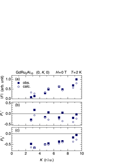
In the horizontal scattering plane configuration, we performed the scans for several reflections of along the axis. The parameters obtained, the scattering amplitude , , and , using Eqs. (8) and (9), are shown in Fig. 8, where the observed values are compared with those of calculations assuming the modified cycloidal structure. The - contribution is also taken into account to explain the result of for . As shown in Fig. 8(a), the calculation well explains the observed . If the parameter deviates from , the agreement becomes worse, indicating that the nearest-neighbor moments of Gd-1 and Gd-2 are antiferromagnetically coupled. The result of in (c) is also well explained by the present magnetic structure model. However, disagreement remains in the parameter as shown in (b). In the experiment, systematically oscillates between positive and negative, whereas in the calculation it is always negative. The relative amplitude and the phase parameter of the additional - term with respect to the main term were chosen so that the result for in Fig. 6 was well reproduced. As a result, it seems that the data for the reflections in Fig. 8(b) are well explained, whereas those for are not explained. Unfortunately, this disagreement cannot be improved in the present model.
3.4 Spin-flop transition in a magnetic field
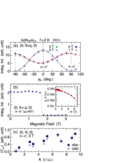
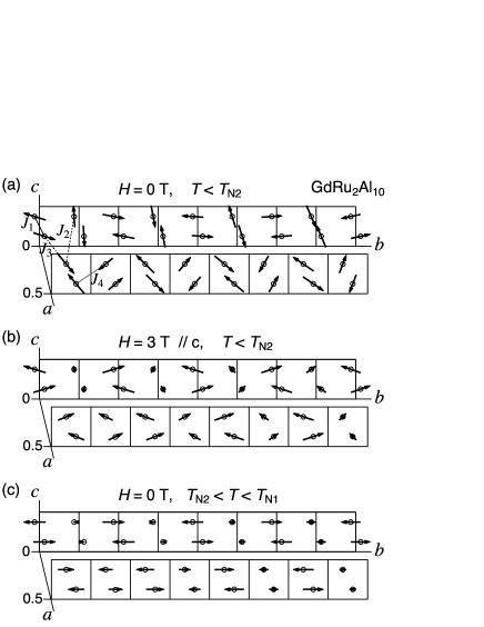
Figure 9(a) shows the scans at in magnetic fields along the axis. At 0 and 1 T, the intensity does not vanish at any , reflecting the cycloidal structure with both the and axis components. At 2 and 3 T above the transition field, the dependence markedly changes and the - intensity completely vanishes. The magnetic field dependence of the - intensity is shown in Fig. 9(b). The disappearance of the - intensity above 1.7 T shows that the axis component vanishes. As shown in the inset, the value continuously and slightly decreases with increasing field. The scattering vector dependence of the scattering amplitude for - is shown in Fig. 9(c). This result can be well explained by assuming a model structure with the axis component only, as shown by the open circles. If we include the axis component, the data in Fig. 9(c) cannot be reproduced. The magnetic structures at 0 and 3 T are summarized in Fig. 10.
The transition in the magnetic structure from Fig. 10(a) to 10(b) can be interpreted as a normal spin-flop transition, where the antiferromagnetic component parallel to the field vanishes and the moments become perpendicular to the field. They are canted to the field, giving rise to a ferromagnetic component. In Fig. 10(b), the ferromagnetic axis component is assumed uniform. Since the axis component is incommensurate, there are sites where the magnitude of the magnetic moment becomes small. However, such sites should have a larger component. If this is the case, it will give rise to higher harmonic intensities. The search for higher harmonics in magnetic fields, however, has not been performed.
3.5 Temperature-dependent cycloidal structure
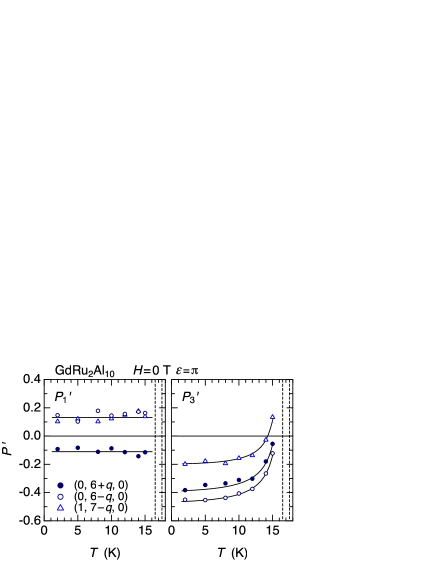
Figure 11 shows the temperature dependence of the Stokes parameters and , which was obtained from scans performed at several temperatures up to . Although remains constant up to , exhibits a strong temperature dependence on approaching . If the magnetic structure remains cycloidal in the whole temperature range, as described by the model structure, these parameters should not change with the temperature. This result therefore shows that a significant change in the cycloidal structure takes place upon increasing the temperature to .
The temperature dependence of in Fig. 11 can be interpreted as a change in the -axis component. Observing in detail the magnetic susceptibility, only shows a cusp at K and monotonically increases down to K. This shows that only the -axis component is ordered below and the -axis component is ordered below . Without the -axis component, which is perpendicular to the scattering plane here, the - scattering is forbidden and only the - scattering takes place. In such a situation, should be realized. Although there are no data points above 15 K in Fig. 11 because of the weak intensity, it seems that increases to unity on approaching . The temperature dependence of therefore reflects the ratio of the -axis component to the -axis component in the cycloid, which increases from nearly zero at to unity at the lowest temperature. By comparison with the calculation, the ratio at 15 K is estimated to be . The magnetic structure expected in the intermediate phase is shown in Fig. 10(c) by assuming that the -axis component is zero.
4 Discussion
In GdRu2Al10, the propagation vector changes with the temperature in proportion to the magnitude of the ordered moment. This shows that the RKKY interaction itself changes with the evolution of the ordered moment.[26] The magnetic propagation vector reflects the position where the exchange interaction , the Fourier transform of , is maximum. for the RKKY interaction is associated with the local - exchange interaction and of the conduction electron system, where is determined by the form of the energy band structure. When a magnetic order develops on the Gd sites with a propagation vector , as described in Eqs. (3) and (4), a perturbation of the exchange field to the conduction electron system arises, which is also described by the same vector. As a result, a gap appears in the region of the Fermi surface where is satisfied.[27] This gap slightly modifies , and therefore the RKKY interaction itself is also modified, resulting in a shift of the vector.[28] Then, the shift of the vector from the original value of just below becomes almost proportional to the ordered moment that develops. A similar temperature dependence of the vector has also been reported in GdSi, GdNi2B2C, and GdPd2Al3.[29, 30, 31, 32].
Note that when the magnetic anisotropy is taken into account, the temperature dependence of the vector becomes more complicated, as observed in rare-earth metals.[26] When there is a uniaxial anisotropy, a squaring up occurs and the third harmonic peak develops with decreasing temperature. This effect also causes the vector to shift from . However, in this case, if we neglect the change in , the temperature dependence of the shift becomes proportional to , which is different from the present case of Gd-based compounds.[26, 33]
The cycloidal structure realized in GdRu2Al10 is associated with the very weak magnetic anisotropy of the state. In other isostructural RAl10 compounds the orientation of the magnetic moment is confined to be in a specific crystallographic axis because of the strong crystal field anisotropy and the nonvanishing orbital moment. As a result, the incommensurate magnetic structure with a propagation vector of with to 0.8 necessarily induces a squaring up structure at low temperatures, giving rise to the appearance of the third harmonic component. In the case of GdRu2Al10 without such a uniaxial anisotropy, Gd spins can be oriented in any direction in the plane. Combination with the maximum at and the -plane anisotropy results in the cycloidal structure, which can release full magnetic entropy without forming a squaring up structure. Although it is very weak, however, an anisotropy exists with preferential ordering along the axis. This is actually observed in the magnetic structure just below K, where the most intrinsic local anisotropy as well as the intrinsic vector of the RKKY interaction can be observed because of the extremely small perturbation to the Fermi surface caused by the ordered moment. To obtain knowledge on the mechanism of the -axis anisotropy, further analysis is required by considering the anisotropy of the conduction electrons due to the spin-orbit interaction, which interacts with the electrons of Gd, as well as the dipole-dipole interaction between the Gd spins.[34]
The modification of the cycloidal structure with from the ideal one with is associated with the non-Bravais lattice of the Gd atoms. Since there is an intersite interaction between the magnetic moments at Gd-1 and Gd-2 sites, the perfect cycloid that should be realized in a single Bravais lattice is modified.
Finally, it is anomalous that only CeAl10 among the RAl10 compounds has the magnetic propagation vector of . The fact that all the magnetic structures of the RAl10 compounds reported to date have a -vector with shows that the RKKY interaction of this system favors this vector. Note, however, that it is not a simple problem to connect this common vector to the Fermi surface structure reported for LaRu2Al10 since the Fermi surface does not seem to possess any particular nesting property.[10] In any case, the propagation vector of CeAl10 is unusual and must be strongly associated with the Kondo semiconducting state caused by strong - hybridization.
5 Conclusion
We performed resonant X-ray diffraction experiments to clarify the magnetic structure of GdRu2Al10 and showed that a modified cycloidal structure propagating along the axis is realized in the plane. The vector shows a temperature dependence that is proportional to the magnetic order parameter, which was interpreted as being associated with partial gap formation in the conduction band and the resultant change in the magnetic exchange interaction. We also showed that the scattering involves not only the - resonance of magnetic dipole origin but also the -forbidden - scattering. We interpreted this signal as being caused by the - resonance due to the toroidal moments at the Gd sites, which is induced by the noncentrosymmetry and the magnetic order. The spin-flop transition for was also studied and it was shown that the cycloidal structure changes to a canted incommensurate structure with the antiferromagnetic moments oriented along the axis. These properties were ascribed to the weak magnetic anisotropy of Gd ions with , which show a slight preference for ordering along the axis, and the RKKY interaction mediated by the conduction electrons, which preferentially takes the vector near .
Acknowledgements
This work was supported by JSPS KAKENHI Grant Number 15K05175. The synchrotron experiments were performed under the approval of the Photon Factory Program Advisory Committee (No. 2014G-129 and No. 2016G-159).
References
- [1] J. Otsuki, H. Kusunose, and Y. Kuramoto, J. Phys. Soc. Jpn. 78, 034719 (2009).
- [2] Y. Muro, K. Motoya, Y. Saiga, and T. Takabatake, J. Phys. Soc. Jpn. 78, 083707 (2009).
- [3] T. Nishioka, Y. Kawamura, T. Takesaka, R. Kobayashi, H. Kato, M. Matsumura, K. Kodama, K. Matsubayashi, and Y. Uwatoko, J. Phys. Soc. Jpn. 78, 123705 (2009).
- [4] A. M. Strydom, Physica B 404, 2981 (2009).
- [5] H. Tanida, D. Tanaka, M. Sera, C. Moriyoshi, Y. Kuroiwa, T. Takesaka, T. Nishioka, H. Kato, and M. Matsumura, J. Phys. Soc. Jpn. 79, 043708 (2010).
- [6] H. Tanida, D. Tanaka, M. Sera, C. Moriyoshi, Y. Kuroiwa, T. Takesaka, T. Nishioka, H. Kato, and M. Matsumura, J. Phys. Soc. Jpn. 79, 083701 (2010).
- [7] J. Robert, J.-M. Mignot, G. André, T. Nishioka, R. Kobayashi, M. Matsumura, H. Tanida, D. Tanaka, and M. Sera, Phys. Rev. B 82, 100404(R) (2010).
- [8] S. I. Kimura, T. Iizuka, H. Miyazaki, T. Hajiri, M. Matsunami, T. Mori, A. Irizawa, Y. Muro, J. Kajino, and T. Takabatake, Phys. Rev. B 84, 165125 (2011).
- [9] A. Kondo, J. Wang, K. Kindo, Y. Ogane, Y. Kawamura, S. Tanimoto, T. Nishioka, D. Tanaka, H. Tanida, and M. Sera, Phys. Rev. B 83, 180415(R) (2011).
- [10] M. Sakoda, S. Tanaka, E. Matsuoka, H. Sugawara, H. Harima, F. Honda, R. Settai, Y. Onuki, T. D. Matsuda, and Y. Haga, J. Phys. Soc. Jpn. 80, 084716 (2011).
- [11] J. Robert, J.-M. Mignot, S. Petit, P. Steffens, T. Nishioka, R. Kobayashi, M. Matsumura, H. Tanida, D. Tanaka, and M. Sera, Phys. Rev. Lett. 109, 267208 (2012).
- [12] D. D. Khalyavin, A. D. Hillier, D. T. Adroja, A. M. Strydom, P. Manuel, L. C. Chapon, P. Peratheepan, K. Knight, P. Deen, C. Ritter, Y. Muro, and T. Takabatake, Phys. Rev. B 82, 100405 (2010).
- [13] D. D. Khalyavin, D. T. Adroja, P. Manuel, J. Kawabata, K. Umeo, T. Takabatake, and A. M. Strydom, Phys. Rev. B 88, 060403(R) (2013).
- [14] R. Kobayashi, K. Kaneko, K. Saito, J.-M. Mignot, G. Andre, J. Robert, S. Wakimoto, M. Matsuda, S. Chi, Y. Haga, T. D. Matsuda, E. Yamamoto, T. Nishioka, M. Matsumura, H. Tanida, and M. Sera, J. Phys. Soc. Jpn. 83, 104707 (2014).
- [15] J. Robert, F. Damay, K. Saito, A. M. Bataille, F. Porcher, G. Andre, A. Gukasov, J.-M. Mignot, H. Tanida, and M. Sera, Phys. Rev. B 90, 224425 (2014).
- [16] S. Takai, T. Matsumura, H. Tanida, and M. Sera, Phys. Rev. B 92, 174427 (2015).
- [17] M. Reehuis, M. W. Wolff, A. Krimmel, E.-W. Scheidt, N. Stüsser, A. Loidl, and W. Jeitschko, J. Phys.: Condens. Matter 15, 1773 (2003).
- [18] M. Sera, H. Nohara, M. Nakamura, H. Tanida, T. Nishioka, and M. Matsumura, Phys. Rev. B 88, 100404(R) (2013).
- [19] J. P. Hannon, G. T. Trammell, M. Blume, and D. Gibbs, Phys. Rev. Lett. 61, 1245 (1988).
- [20] V. M. T. Thiede, T. Ebel, and W. Jeitschko, J. Mater. Chem. 8, 125 (1998).
- [21] M. Sera, D. Tanaka, H. Tanida, C. Moriyoshi, M. Ogawa, Y. Kuroiwa, T. Nishioka, M. Matsumura, J. Kim, N. Tsuji, and M. Takata, J. Phys. Soc. Jpn. 82, 024603 (2013).
- [22] T. Nagao and J. Igarashi, Phys. Rev. B 72, 174421 (2005).
- [23] T. Nagao and J. I. Igarashi, Phys. Rev. B 74, 104404 (2006).
- [24] S. W. Lovesey, E. Balcar, K. S. Knight, and J. Fernández Rodríguez, Phys. Rep. 411, 233 (2005).
- [25] S. W. Lovesey and E. Balcar, J. Phys. Soc. Jpn. 79, 074707 (2010).
- [26] J. Jensen and A. R. Mackintosh, Rare Earth Magnetism (Clarendon Press, Oxford, 1991).
- [27] R. E. Watson, A. J. Freeman, and J. P. Dimmock, Phys. Rev. 167, 497 (1968).
- [28] R. J. Elliot and F. A. Wedgwood, Proc. Phys. Soc. 84, 63 (1964).
- [29] Y. Feng, J. Wang, D. M. Silevitch, B. Mihaila, J. W. Kim, J.-Q. Yan, R. K. Schulze, N. Woo, A. Palmer, Y. Ren, J. van Wezel, P. B. Littlewood, and T. F. Rosenbaum, Proc. Natl. Acad. Sci. U.S.A. 110, 3287 (2013).
- [30] Y. Feng, D. M. Silevitch, J. Wang, A. Palmer, N. Woo, J.-Q. Yan, Z. Islam, A. V. Suslov, P. B. Littlewood, and T. F. Resenbaum, Phys. Rev. B 88, 134404 (2013).
- [31] C. Detlefs, A. I. Goldman, C. Stassis, P. C. Canfield, B. K. Cho, J. P. Hill, and D. Gibbs, Phys. Rev. B 53, 6355 (1996).
- [32] T. Inami, N. Terada, H. Kitazawa, and O. Sakai, J. Phys. Soc. Jpn. 78, 084713 (2009).
- [33] T. Sato, H. Kadowaki, H. Masuda, and K. Iio, J. Phys. Soc. Jpn. 63, 4583 (1994).
- [34] M. Colarieti-Tosti, S. I. Simak, R. Ahuja, L. Nordström, O. Eriksson, D. Åberg, S. Edvardsson, and M. S. S. Brooks, Phys. Rev. Lett. 91, 157201 (2003).