Janus and Huygens’ dipolar sources for near-field directionality
Abstract
Controlling directionality of emission, scattering and waveguiding is an important requirement in quantum optical technology, integrated photonics and new metasurface designs, as well as radio and microwave engineering. Recently, several approaches have been developed to achieve unidirectional scattering in the far-field relying on Huygens’ dipolar sources, and in waveguided optics based on spin-Hall effects involving circularly polarised electric or magnetic dipoles, all of which can be realised with plasmonic or dielectric nanoparticles. Here we show that there exists a dipolar source complimentary to Huygens’ dipole, termed Janus dipole, which is not directional in the far-field, but its coupling to waveguided modes is topologically protected so that it is allowed on one side of the dipole but not on the opposite side. The near field directionality of the Huygens’ dipole is also revealed and a generalised Kerker’s condition for far- and near-field directionality is introduced. Circular electric and magnetic dipoles, together with Huygens’ and Janus dipolar sources, form a complete set of directional dipolar sources in far- and near-field, paving the way for promising applications.
pacs:
Valid PACS appear hereNanoscale emitters, scatterers and their assemblies have been recently considered for scalable photonic circuitry, where the requirements on miniaturization and efficient coupling to photonic modes are strict, metasurface designs enabling flat lenses and hologrammes, as well as quantum optical technologies Photonics2014 ; yu2014flat ; chang2014quantum . They can be realised as strongly resonant plasmonic or high-index dielectric nanoparticles supporting electric and/or magnetic dipolar resonances. Going beyond linearly polarised dipoles opens unexpected opportunities for electromagnetic designs. Near field interference and related directional excitation of fields from circularly polarized electric and magnetic dipoles Rodriguez-Fortuno2013 ; Kapitanova2014 ; Aiello2015 ; Espinosa-Soria2016 ; Mechelen2015 ; Coles2016 ; LeFeber2015 ; zharov2016control ; wang2017photonic ; garoli2017helicity ; picardi2017unidirectional have fascinating applications in quantum optics marrucci2015quantum ; Luxmoore2013 ; mitsch2014quantum and in novel nanophotonic devices such as nanorouters, polarimeters, and non-reciprocal optical components Petersen2014 ; Neugebauer2014 ; espinosa2017chip ; OConnor2014 ; rodriguez2014universal ; rodríguez2014resolving ; rodriguez2014sorting ; sayrin2015nanophotonic ; ma2016hybrid . These effects rely on the photonic spin-Hall effect exploiting the phenomenon of spin-momentum locking in evanescent and guided waves bliokh2015quantum ; bliokh2012transverse ; Junge2013 ; bliokh2014extraordinary : in essence, the spin of the dipole can be matched to the spin of the guided fields to be directionally excited. While electromagnetic spin is a quantity that accounts for the relative amplitude and phase of the different electric field or magnetic field components of a guided wave –describing the rotation of these two vectors and – spin does not account for the relative amplitude and phases between electric and magnetic components. Engineering superpositions of electric and magnetic dipoles and their interference sinev2017dielectric ; lee2012role ; evlyukhin2015resonant ; fu2012directional takes care of this limitation.
There is a well-known dipolar source which explicitly exploits these relations to achieve far-field directionality: the Huygens’ antenna. This source combines two orthogonal linearly polarized electric and magnetic dipoles (Fig. 1) satisfying Kerker’s condition kerker1983electromagnetic ; zambrana2013duality :
| (1) |
with being the speed of light. The radiation diagram of such an antenna is highly directional and has zero back-scattering, due to the interference of magnetic and electric dipole radiation. These antennas are attracting great attention due to the feasibility of implementing them using high-index dielectric nanoparticles evlyukhin2012demonstration ; permyakov2015probing ; kuznetsov2016optically , with applications in null back-scattering, metasurfaces, and all-dielectric mirrors geffrin2012magnetic ; person2013demonstration ; staude2013tailoring ; nieto2011angle ; coenen2014directional ; wei2017adding ; paniagua2016generalized .
Here we show that Huygens’ sources can be generalized to achieve near-field directionality, and that there exists a dipolar source complementary to a Huygen’s dipole, which we term Janus dipole, with a different relation between the phases of electric and magnetic dipoles, which is not directional in the far-field, but has unique near-field properties allowing “side”-dependent coupling to guided modes. Together, Huygens’, Janus, circular electric and magnetic dipoles (as well as the infinite spectrum of their linear combinations) provide a general closed solution to dipolar far- and near-field directionality that takes into account the topology of the vector structure of free space and guided electromagnetic fields. These dipolar sources can be experimentally realised as plasmonic, dielectric and hybrid nanoparticles.
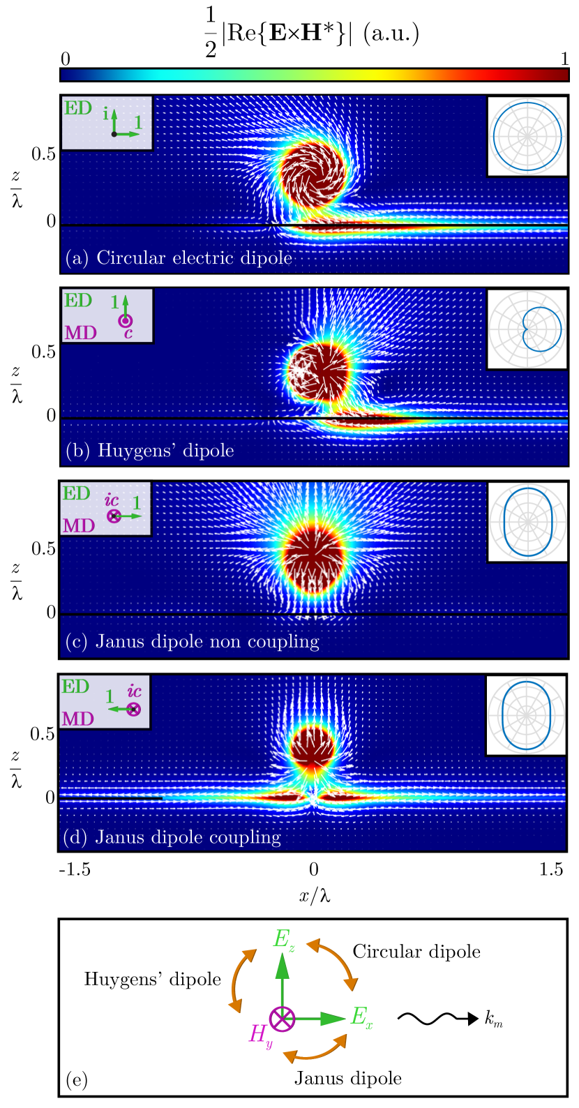
In order to illustrate the properties of the considered dipolar sources, Figure 1 shows the time averaged power flow vector generated by (a) a circular dipole, (b) a Huygens’ antenna, and (c,d) a Janus dipole for its two orientations, all placed over a waveguiding surface. We used metallic surfaces supporting surface plasmons as simple examples, but the directionality of the dipoles is universal and completely independent of the waveguide’s nature. As can be seen, the first two sources lead to directional evanescent wave excitation of guided modes along the waveguide. While this is known for circular dipoles Rodriguez-Fortuno2013 ; Kapitanova2014 ; Aiello2015 ; Espinosa-Soria2016 ; Mechelen2015 ; Coles2016 ; LeFeber2015 ; zharov2016control ; wang2017photonic ; garoli2017helicity ; Junge2013 ; picardi2017unidirectional , Huygens’ antennas have been massively studied for their strong directional radiation diagram, but their near field directionality had not been explored. The direction of excitation of these sources can be switched by flipping the sign of one of their two dipole components, which can be experimentally achieved tuning polarization and wavelength of the light illuminating the nanoparticle, with respect to its electric and magnetic resonances.
The Janus dipole has an intriguing property: it either shows (c) a complete absence of coupling, in which it does not excite waveguide modes at all or (d) excitation of the guided mode in both directions. This is determined by which ‘side’ of the dipole is facing the waveguide. Inverting the sign of one component in the Janus dipole will change the side facing the waveguide, like when flipping a coin, and this will switch the coupling on and off [Figs. 1(c,d)].
An intuitive explanation of the three sources can be obtained as follows. Fermi’s golden rule Aiello2015 ; Luxmoore2013 ; Coles2016 ; LeFeber2015 ; marrucci2015quantum ; Mechelen2015 ; Espinosa-Soria2016 dictates that the coupling efficiency between an electric and magnetic dipole source and a waveguide mode is proportional to where and are the electric and magnetic fields of the mode calculated at the location of the dipoles, and is the permeability of the medium. In Fig. 1, the dipoles are interacting with a -polarized waveguide mode, so the only non-zero field components are the transverse electric and magnetic fields and , and the longitudinal field . These are shown in Fig. 1(e). The circular dipole uses the dipole components and to couple with the and components of the mode. Its directional behaviour relies on the well understood spin-momentum locking between these components, which dictates that and undergo a fixed amplitude and phase relationship, resulting in having a circular polarization, associated with a transverse spin, whose sense of rotation depends on the propagation direction Junge2013 ; Aiello2015 ; Mechelen2015 ; bliokh2012transverse ; bliokh2014extraordinary ; bliokh2015quantum . The dipole exploits this such that for the mode propagating to the left or right, thereby showing unidirectional excitation in the opposite direction. Analogously, circular magnetic dipoles can directionally excite -polarized modes by exploiting . Both are possible thanks to the longitudinal component of the evanescent fields.
To describe the nature of the other two sources, however, we must also take into account the relative phase and amplitude between the and components, not usually considered in spin-direction locking. Their relation can be exploited such that the electric and magnetic coupling terms interfere destructively between each other . In other words, the mode excited by the electric dipole in a given direction is exactly cancelled out by the one excited by the magnetic dipole after their superposition. The Huygens’ source exploits the fixed relative amplitude and phase that exists between the transverse field components and , which depends on the propagation direction of the mode. This relation is a well-known property of plane waves which extends directly into evanescent and guided waves.
On the other hand, there is another pair of components that we can consider [Fig. 1(e)]. The Janus dipole exploits the locked amplitude and phase relation that exists between and the longitudinal electric field . The unique feature of the Janus dipole, which distinguishes it from the other two, is that this interference can be achieved simultaneously in both propagation directions of a mode, because the ratio between and is independent of the mode’s left or right propagation direction. This is a remarkable topological feature of evanescent wave polarization in addition to transverse spin bliokh2015quantum . It enables us to design an electric dipole and magnetic dipole such that their mode excitations interfere destructively in both directions. Note that the independence of the ratio between longitudinal electric field and transverse magnetic field with respect to the propagation direction (time reversal) is universally true, at any location, on any translationally invariant waveguide. This can be proven by considering a mirror reflection on a plane perpendicular to the waveguide axis: the propagation direction changes, but the ratio of the two components does not, due to the simultaneous flipping of both the longitudinal component and the magnetic component, which being a pseudo-vector changes sign under reflections. Thus, a Janus dipole can be designed to achieve polarization and position-dependent “non-coupling” in any scenario where longitudinal fields are present, such as inside nanowires and photonic crystal waveguides, not being limited to evanescent coupling as illustrated here.
Both the circular and Janus dipole involve the longitudinal component of the field, while the Huygens’ source does not. This explains why circular and Janus dipoles are not directional in the far field Rodriguez-Fortuno2013 ; picardi2017unidirectional , as plane waves have no longitudinal field. The Huygens’ source, instead, is always directional, as it exploits the relation between the transverse fields which exists in plane waves and evanescent waves alike. Another crucial difference lies in the intrinsic symmetry of the sources themselves. The circular dipole has rotational symmetry around the axis. The Huygens’ source –recalling that the magnetic moment is a pseudo-vector– is mirror symmetric with respect to the plane, while the Janus source is mirror symmetric with respect to the one. This difference in symmetry leads to a remarkable result when considering coupling of the dipoles surrounded by waveguides.
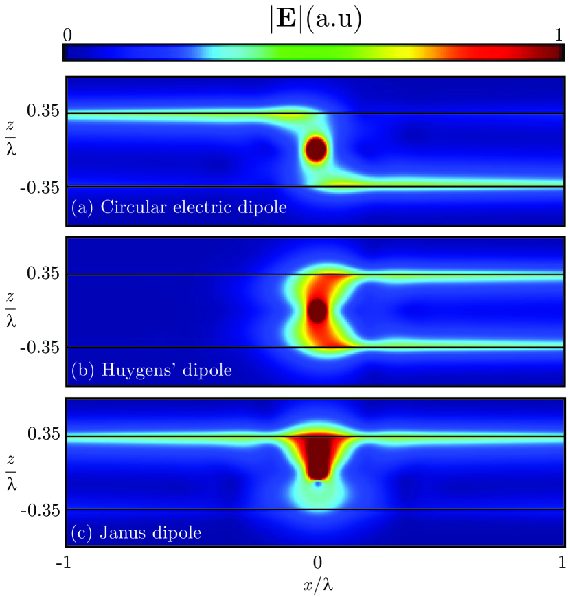
Figure 2 shows the three dipole sources embedded between two waveguides, again metallic surfaces only as an example, at a distance such that light from the dipole can couple to both waveguides, but with negligible coupling between the waveguides for the propagation distances considered. The circular dipole couples into opposite directions for the waveguides placed above or below the dipole, while the Huygens’ dipole couples in the same direction for both. Most interestingly, while these two sources exhibit left-right directionality, the Janus dipole exhibits a front-back directionality. While it does not excite the waveguide placed below, it does however excite both directions in the waveguide above it, regardless of its distance to either. In this way, the Janus dipole is topologically protected from coupling into the waveguide facing its non-coupling side. This arises because the ratio between and in evanescent waves is independent of the propagation direction but does depend on the direction of evanescent decay. This remarkable and inherently broadband behaviour suggests novel potential applications in optical nanorouting and signal processing. Importantly, all the directionality properties described in Fig. 2 are robust and independent of the distance of the dipoles to the waveguides. The symmetry of excitations follows directly from that of the sources themselves.
The design of dipoles exhibiting near-field interference can be done in a general case by means of the Fermi golden rule, as long as the modal fields are known. However, we can provide simple expressions for the specific case of dipoles coupling into the evanescent fields of a planar waveguide extending along the transverse plane (Figs. 1 and 2). For simplicity, we can align our reference system with the propagation direction of the mode, such that the wave-vector of the evanescent field is given by , where is the propagation constant of the mode, accounts for the evanescent nature and is the wave-number of the medium. The sign of accounts for the direction of propagation, while the sign of depends on the direction of evanescent decay, which depends on whether the waveguide is below (positive) or above (negative) the dipole. We can write the three components of -polarized modes in a vector of the form and the corresponding dipole moment components as a vector so that the Fermi’s golden rule is reduced to a simple scalar product . Maxwell’s equations demand that -polarized fields with are given by picardi2017unidirectional , irrespective of the nature of the waveguide. The single key aspect underpinning all phenomena described in this work is that each pair of these three components has a fixed amplitude and phase relation between them. Indeed, each of the three elemental dipole sources is derived from the relationship between each of the three possible pairs of field components [Fig. 1(e)]. Notice that the ratio between and depends on both the direction of propagation and on the sign of the evanescent decay (evanescent field gradient) , as known for spin-direction locking. The ratio between and depends only on propagation direction, thus explaining Huygens’ properties, while the ratio between and is independent of the propagation direction, as proved earlier in a general case, but depends on the sign of , explaining the unique behaviour of the Janus dipole.
To obtain near-field interference effects, we can solve the equation that achieves zero coupling of the dipoles into a given mode:
| (2) |
Mathematically, this simple equation defines a geometric plane of solutions given by the sub-space of dipole vectors which are orthogonal to , and provides a unified view of all the possible ways to achieve directionality of -polarized modes when using any electric and magnetic dipole source. The fixed relationships between the field components translate directly into conditions between the dipole components. Each of the three sources discussed above correspond to intersections of this plane with the , , or planes. Alternatively, each dipole corresponds to the intersection of two planes given by Eq. 2 but for different pairs of sign combinations in and , explaining why each case shows zero excitation of exactly two directions in Fig. 2. A compact summary of the mathematical solutions to this equation is given in Table 1. Notice that the dipoles are fine-tuned to achieve a perfect contrast ratio for a specific mode , but the non-optimized versions, in which , and , also work remarkably well as shown in Fig. 1. Each of the three elemental sources corresponds to a vector within the same plane of solutions, so that each is obtainable as a linear superposition of the other two. Finally, we can consider the entire geometric plane of solutions obtained by linear combinations of the elemental sources, resulting in an infinite range of electric and magnetic dipoles that verify Eq. 2.
| -polarization | -polarization | |
|---|---|---|
| Elliptical | ||
| Huygens | ||
| Janus | ||
| General |
Analogous considerations are valid for polarized modes. In this case, Maxwell’s equations imply that the electromagnetic fields when are given by , and writing the relevant dipole components as , the near-field destructive interference condition based on Fermi’s golden rule can be written as . Solutions are given in Table 1. In complete physical analogy to the -polarized case, the same three elemental dipoles can be derived, but swapping the roles of the electric and magnetic moments.
The optimized conditions for the Huygens’ and Janus dipoles can be written compactly as:
| (3) |
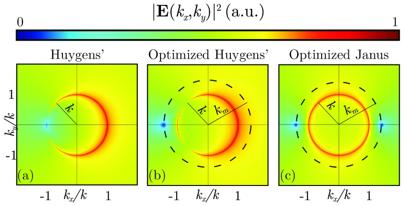
The first equation corresponds to the Huygens’ dipole and constitutes a generalized Kerker’s condition which works for both evanescent and propagating waves. It, in fact, reduces to the usual Kerker’s condition (Eq. 1) for . The angular spectrum of the source supplementarycite provides a convincing visual explanation of this optimization. In Fig. 3 we plot the angular spectrum of the fields below a Huygens’ antenna in two different cases. Panel (a) corresponds to the usual Kerker’s condition (Eq. 1), and it can be seen that the spectrum is zero on the transverse wave-vector , lying exactly on the light cone. In panel (b) we show the spectra of the generalized Huygens’ dipole (Eq. 3), and we see that it is zero at , corresponding to the mode supported by the waveguide. Comparing the amplitude of both spectra at , both cases will excite modes preferentially in the direction , but only the optimized Kerker condition will achieve a perfect contrast ratio. The second Eq. 3 corresponds to the Janus dipole and, in the limit reduces to . It greatly resembles Kerker’s condition but with a phase difference. The angular spectrum of the Janus dipole is shown in Fig. 3(c) and shows a null spectral component for both and . Thus from simple momentum matching arguments, the dipole itself is incapable of coupling into the modes of the waveguide at all because it lacks the required angular components. While the above considerations have been derived for a planar waveguide, we would like to emphasize that following a spectral interpretation, all dipoles derived in Table 1 are excellent approximations to their optimum when placed near arbitrary waveguides, as was shown in Ref. picardi2017unidirectional based on momentum conservation arguments.
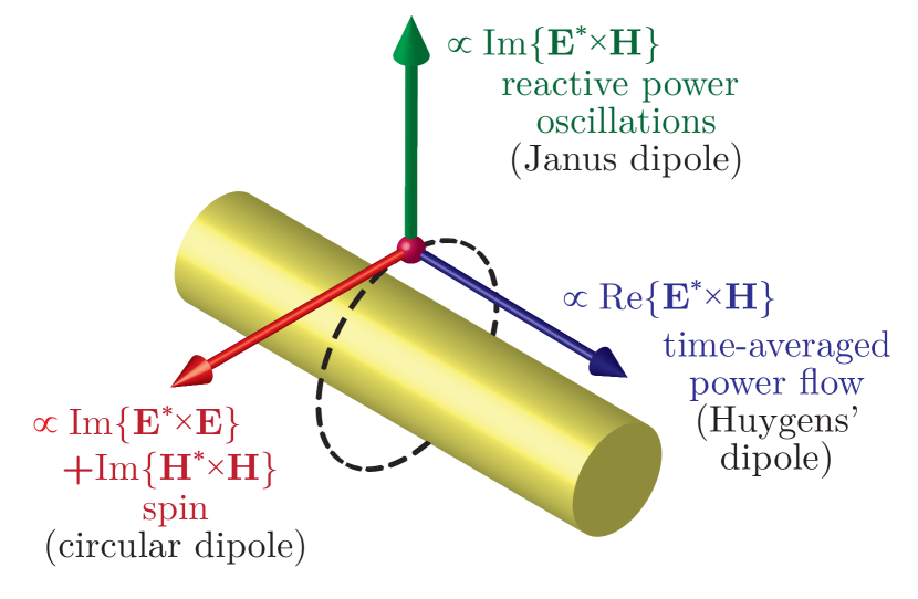
Further insight can be obtained using well-known electromagnetic quantities (Fig. 4). The Huygens’ source is often explained in terms of the time-averaged Poynting vector ; it uses orthogonal electric and magnetic dipoles, in phase, to produce the corresponding fields associated with a net power flow in a given direction. The canonical spin angular momentum accounts for the spin of vectors and , arising when either field has orthogonal components phase-shifted by , exactly as generated by circular dipoles. The Janus dipole is associated with the vector . This expression resembles that of spin, but mixing electric and magnetic components. It arises when and are orthogonal and out of phase, as produced by the Janus dipole. Notice that this vector is the imaginary part of the complex Poynting vector, known to signify the direction of reactive power in which harmonic oscillations of power occur with no net flow. The vector points in the direction of evanescent decay. The Janus dipole can thus match or oppose these oscillations. The three vector quantities, each associated with one of the sources, are known to form a locked triad at each point near a waveguide Mechelen2015 , as shown in Fig. 4, accounting for the sources’ symmetries and behaviour.
Previous approaches to guided optics directionality from dipolar sources made use of the spin of the guided mode’s fields and , neglecting their mutual amplitude and phase relations. By considering the whole vector structure of electromagnetic fields we provide a unified theory describing all possible dipole sources exhibiting far- and near-field directionality, opening the way to entirely new types of directional coupling. The implementation of these new sources using resonant plasmonic or dielectric nanoparticles and their integration in photonic circuitry will provide a step change in the already broad range of near-field directionality applications which are currently based on circular dipoles exclusively. We expect novel ideas to emerge in quantum optics, photonic nano-routing, photonic logical circuits, optical forces and torques of particles in near-field environments, inverse and reciprocal scenarios for polarization synthesis, integrated polarimeters, and other unforeseen devices throughout the whole electromagnetic spectrum.
I Acknowledgements
This work was supported by European Research Council Starting Grant ERC-2016-STG-714151-PSINFONI and EPSRC (UK). A.Z. acknowledges support from the Royal Society and the Wolfson Foundation. All data supporting this research is provided in full in the main text.
References
- [1] Nature Photonics. Not so small. Nature Photonics, 8(12):877–877, 2014.
- [2] Nanfang Yu and Federico Capasso. Flat optics with designer metasurfaces. Nature materials, 13(2):139, 2014.
- [3] Darrick E Chang, Vladan Vuletić, and Mikhail D Lukin. Quantum nonlinear optics [mdash] photon by photon. Nature Photonics, 8(9):685–694, 2014.
- [4] F. J. Rodríguez-Fortuño, Giuseppe Marino, Pavel Ginzburg, Daniel O’Connor, A. Martinez, Gregory A. Wurtz, and Anatoly V. Zayats. Near-Field Interference for the Unidirectional Excitation of Electromagnetic Guided Modes. Science, 340(6130):328–330, apr 2013.
- [5] Polina V. Kapitanova, Pavel Ginzburg, Francisco J. Rodríguez-Fortuño, Dmitry S. Filonov, Pavel M. Voroshilov, Pavel A. Belov, Alexander N. Poddubny, Yuri S. Kivshar, Gregory A. Wurtz, and Anatoly V. Zayats. Photonic spin Hall effect in hyperbolic metamaterials for polarization-controlled routing of subwavelength modes. Nature Communications, 5, feb 2014.
- [6] Andrea Aiello, Peter Banzer, Martin Neugebauer, and Gerd Leuchs. From transverse angular momentum to photonic wheels. Nature Photonics, 9(12):789–795, nov 2015.
- [7] Alba Espinosa-Soria and Alejandro Martinez. Transverse Spin and Spin-Orbit Coupling in Silicon Waveguides. IEEE Photonics Technology Letters, 28(14):1561–1564, jul 2016.
- [8] Todd Van Mechelen and Zubin Jacob. Universal spin-momentum locking of evanescent waves. Optica, 3(2):118, feb 2016.
- [9] R. J. Coles, D. M. Price, J. E. Dixon, B. Royall, E. Clarke, P. Kok, M. S. Skolnick, A. M. Fox, and M. N. Makhonin. Chirality of nanophotonic waveguide with embedded quantum emitter for unidirectional spin transfer. Nature Communications, 7:11183, mar 2016.
- [10] B. le Feber, N. Rotenberg, and L. Kuipers. Nanophotonic control of circular dipole emission. Nature Communications, 6:6695, apr 2015.
- [11] AA Zharov and NA Zharova. Control of surface plasmon excitation via the scattering of light by a nanoparticle. Journal of Experimental and Theoretical Physics, 123(1):17–26, 2016.
- [12] Ying-Hua Wang, Ren-Chao Jin, Jia-Qi Li, Fan Zhong, Hui Liu, Inki Kim, Yongjoon Jo, Junsuk Rho, and Zheng-Gao Dong. Photonic spin hall effect by the spin-orbit interaction in a metasurface with elliptical nano-structures. Applied Physics Letters, 110(10):101908, 2017.
- [13] Denis Garoli, Pierfrancesco Zilio, Francesco De Angelis, and Yuri Gorodetski. Helicity locking of chiral light emitted from a plasmonic nanotaper. Nanoscale, 2017.
- [14] Michela F Picardi, Alejandro Manjavacas, Anatoly V Zayats, and Francisco J Rodríguez-Fortuño. Unidirectional evanescent-wave coupling from circularly polarized electric and magnetic dipoles: An angular spectrum approach. Physical Review B, 95(24):245416, 2017.
- [15] Lorenzo Marrucci. Quantum optics: Spin gives direction. Nature Physics, 11(1):9–10, 2015.
- [16] I. J. Luxmoore, N. A. Wasley, A. J. Ramsay, A. C. T. Thijssen, R. Oulton, M. Hugues, S. Kasture, V. G. Achanta, A. M. Fox, and M. S. Skolnick. Interfacing Spins in an InGaAs Quantum Dot to a Semiconductor Waveguide Circuit Using Emitted Photons. Physical Review Letters, 110(3):037402, jan 2013.
- [17] R Mitsch, C Sayrin, B Albrecht, P Schneeweiss, and A Rauschenbeutel. Quantum state-controlled directional spontaneous emission of photons into a nanophotonic waveguide. Nature communications, 5, 2014.
- [18] J Petersen, J Volz, and A Rauschenbeutel. Chiral nanophotonic waveguide interface based on spin-orbit interaction of light. Science, 346(6205):67–71, 2014.
- [19] Martin Neugebauer, Thomas Bauer, Peter Banzer, and Gerd Leuchs. Polarization tailored light driven directional optical nanobeacon. Nano letters, 14(5):2546–2551, may 2014.
- [20] Alba Espinosa-Soria, Francisco Rodríguez-Fortuño, Amadeu Griol, and Alejandro Martínez. On-chip optimal stokes nanopolarimetry based on spin-orbit interaction of light. Nano Letters, 2017.
- [21] D. O’Connor, P. Ginzburg, F. J. Rodríguez-Fortuño, G. A. Wurtz, and A. V. Zayats. Spin–orbit coupling in surface plasmon scattering by nanostructures. Nature Communications, 5:5327, nov 2014.
- [22] Francisco J Rodríguez-Fortuño, Daniel Puerto, Amadeu Griol, Laurent Bellieres, Javier Martí, and Alejandro Martínez. Universal method for the synthesis of arbitrary polarization states radiated by a nanoantenna. Laser & Photonics Reviews, 8(3):L27–L31, 2014.
- [23] Francisco J Rodríguez-Fortuño, Isaac Barber-Sanz, Daniel Puerto, Amadeu Griol, and Alejandro Martínez. Resolving light handedness with an on-chip silicon microdisk. ACS Photonics, 1(9):762–767, 2014.
- [24] Francisco J Rodríguez-Fortuño, Daniel Puerto, Amadeu Griol, Laurent Bellieres, Javier Martí, and Alejandro Martínez. Sorting linearly polarized photons with a single scatterer. Optics letters, 39(6):1394–1397, 2014.
- [25] Clément Sayrin, Christian Junge, Rudolf Mitsch, Bernhard Albrecht, Danny O’Shea, Philipp Schneeweiss, Jürgen Volz, and Arno Rauschenbeutel. Nanophotonic optical isolator controlled by the internal state of cold atoms. Physical Review X, 5(4):041036, 2015.
- [26] Jingwen Ma, Xiang Xi, Zejie Yu, and Xiankai Sun. Hybrid graphene/silicon integrated optical isolators with photonic spin–orbit interaction. Applied Physics Letters, 108(15):151103, 2016.
- [27] Konstantin Y Bliokh, Daria Smirnova, and Franco Nori. Quantum spin hall effect of light. Science, 348(6242):1448–1451, 2015.
- [28] Konstantin Y Bliokh and Franco Nori. Transverse spin of a surface polariton. Physical Review A, 85(6):061801, 2012.
- [29] Christian Junge, Danny O’Shea, Jürgen Volz, and Arno Rauschenbeutel. Strong Coupling between Single Atoms and Nontransversal Photons. Physical Review Letters, 110(21):213604, may 2013.
- [30] Konstantin Y Bliokh, Aleksandr Y Bekshaev, and Franco Nori. Extraordinary momentum and spin in evanescent waves. Nature Communications, 5, 2014.
- [31] Ivan S Sinev, Andrey A Bogdanov, Filipp E Komissarenko, Kristina S Frizyuk, Mihail I Petrov, Ivan S Mukhin, Sergey V Makarov, Anton K Samusev, Andrei V Lavrinenko, and Ivan V Iorsh. Dielectric nanoantenna as an efficient and ultracompact demultiplexer for surface waves. arXiv preprint arXiv:1705.07689, 2017.
- [32] Seung-Yeol Lee, Il-Min Lee, Junghyun Park, Sewoong Oh, Wooyoung Lee, Kyoung-Youm Kim, and Byoungho Lee. Role of magnetic induction currents in nanoslit excitation of surface plasmon polaritons. Physical review letters, 108(21):213907, 2012.
- [33] Andrey B Evlyukhin and Sergey I Bozhevolnyi. Resonant unidirectional and elastic scattering of surface plasmon polaritons by high refractive index dielectric nanoparticles. Physical Review B, 92(24):245419, 2015.
- [34] Yuan Hsing Fu, Arseniy I Kuznetsov, Andrey E Miroshnichenko, Ye Feng Yu, and Boris Lukiyanchuk. Directional visible light scattering by silicon nanoparticles. arXiv preprint arXiv:1212.3104, 2012.
- [35] Milton Kerker, D-S Wang, and CL Giles. Electromagnetic scattering by magnetic spheres. JOSA, 73(6):765–767, 1983.
- [36] Xavier Zambrana-Puyalto, I Fernandez-Corbaton, ML Juan, Xavier Vidal, and Gabriel Molina-Terriza. Duality symmetry and kerker conditions. Optics letters, 38(11):1857–1859, 2013.
- [37] Andrey B Evlyukhin, Sergey M Novikov, Urs Zywietz, René Lynge Eriksen, Carsten Reinhardt, Sergey I Bozhevolnyi, and Boris N Chichkov. Demonstration of magnetic dipole resonances of dielectric nanospheres in the visible region. Nano letters, 12(7):3749–3755, 2012.
- [38] Dmitry Permyakov, Ivan Sinev, Dmitry Markovich, Pavel Ginzburg, Anton Samusev, Pavel Belov, Vytautas Valuckas, Arseniy I Kuznetsov, Boris S Luk’yanchuk, Andrey E Miroshnichenko, et al. Probing magnetic and electric optical responses of silicon nanoparticles. Applied Physics Letters, 106(17):171110, 2015.
- [39] Arseniy I Kuznetsov, Andrey E Miroshnichenko, Mark L Brongersma, Yuri S Kivshar, and Boris Luk’yanchuk. Optically resonant dielectric nanostructures. Science, 354(6314):aag2472, 2016.
- [40] JM Geffrin, B García-Cámara, R Gómez-Medina, P Albella, LS Froufe-Pérez, Christelle Eyraud, Amelie Litman, Rodolphe Vaillon, F González, M Nieto-Vesperinas, et al. Magnetic and electric coherence in forward-and back-scattered electromagnetic waves by a single dielectric subwavelength sphere. Nature communications, 3:1171, 2012.
- [41] Steven Person, Manish Jain, Zachary Lapin, Juan Jose Sáenz, Gary Wicks, and Lukas Novotny. Demonstration of zero optical backscattering from single nanoparticles. Nano letters, 13(4):1806–1809, 2013.
- [42] Isabelle Staude, Andrey E Miroshnichenko, Manuel Decker, Nche T Fofang, Sheng Liu, Edward Gonzales, Jason Dominguez, Ting Shan Luk, Dragomir N Neshev, Igal Brener, et al. Tailoring directional scattering through magnetic and electric resonances in subwavelength silicon nanodisks. ACS nano, 7(9):7824–7832, 2013.
- [43] M Nieto-Vesperinas, R Gomez-Medina, and JJ Saenz. Angle-suppressed scattering and optical forces on submicrometer dielectric particles. JOSA A, 28(1):54–60, 2011.
- [44] Toon Coenen, Felipe Bernal Arango, A Femius Koenderink, and Albert Polman. Directional emission from a single plasmonic scatterer. Nature communications, 5:3250, 2014.
- [45] Lei Wei, Nandini Bhattacharya, and H Paul Urbach. Adding a spin to kerker’s condition: angular tuning of directional scattering with designed excitation. Optics Letters, 42(9):1776–1779, 2017.
- [46] Ramón Paniagua-Domínguez, Ye Feng Yu, Andrey E Miroshnichenko, Leonid A Krivitsky, Yuan Hsing Fu, Vytautas Valuckas, Leonard Gonzaga, Yeow Teck Toh, Anthony Yew Seng Kay, Boris Luk’yanchuk, et al. Generalized brewster effect in dielectric metasurfaces. Nature communications, 7, 2016.
- [47] Supplementary info available at [link].