The role of symmetry in driven propulsion at low Reynolds number
Abstract
We theoretically and experimentally investigate low-Reynolds-number propulsion of geometrically achiral planar objects that possess a dipole moment and that are driven by a rotating magnetic field. Symmetry considerations (involving parity, , and charge conjugation, ) establish correspondence between propulsive states depending on orientation of the dipolar moment. Although basic symmetry arguments do not forbid individual symmetric objects to efficiently propel due to spontaneous symmetry breaking, they suggest that the average ensemble velocity vanishes. Some additional arguments show, however, that highly symmetrical (-even) objects exhibit no net propulsion while individual less symmetrical (-even) propellers do propel. Particular magnetization orientation, rendering the shape -odd, yields unidirectional motion typically associated with chiral structures, such as helices. If instead of a structure with a permanent dipole we consider a polarizable object, some of the arguments have to be modified. For instance, we demonstrate a truly achiral (- and -even) planar shape with an induced electric dipole that can propel by electro-rotation. We thereby show that chirality is not essential for propulsion due to rotation-translation coupling at low Reynolds number.
I Introduction
Bacteria employ rotation-translation coupling when they spin their helical flagella in order to swim through fluids at low Reynolds (Re) numbers Turner . It is also possible to rotate an artificial magnetic corkscrew to generate propulsion GF ; Nelson . In both cases the rotation-translation coupling arises because of the symmetry-breaking due to the chiral shape. Purcell’s famous remark “Turn anything - if it isn’t perfectly symmetrical, you’ll swim” Purcell raises the question if a shape needs to be chiral to propel when it is spun at low Reynolds number. This issue is, of course, only relevant for swimming in unbounded liquid, as boundaries can provide such coupling even for highly symmetrical driven objects, e.g., isotropic spherical “microrollers” chaikin17 and axisymmetric peanut-shaped colloids peanut18 exhibit net propulsion when rotated by an external field in the vicinity of a solid surface.
For a long time the geometric chirality of the object was taken for granted as a necessary condition for driven propulsion in rotating magnetic GF ; Nelson ; Schmidt ; jacs13 ; acsnano14 and electric fields zeldovich ; MD16 and for cross-stream migration and separation in shear flows shear1 ; shear2 ; shear3 and for Brownian swimmers Lowen1 . Recent experiments with random-shaped magnetic aggregates Vach1 ; Vach2 , as well as clusters made of just three magnetized beads Cheang demonstrated propulsion in a uniform rotating magnetic field. The latter example is particularly intriguing, as it is argued that seemingly “achiral” planar objects are propulsive. Ref. prf17 offered an explicit solution for driven rotation and propulsion of an arbitrarily shaped and magnetized object, establishing the dependence of the propulsion velocity on geometry and orientation of a permanent magnetic dipole moment. It had confirmed that geometric chirality is not required for driven propulsion and proposed that an achiral shape can break symmetry due to nontrivial orientation of its magnetic dipole. The most recent study scirob showed that in agreement with the experiments Vach1 ; Vach2 the fastest random aggregates have a shape of an arc, i.e., having the same symmetry as the three-bead cluster of Cheang .
In the present paper we address symmetry requirements for magnetized objects to propel when acted upon by an external torque and show that chirality alone does not predict if an individual structure propels. Instead it only predicts whether a net propulsion persists after averaging over random initial orientations in a large ensemble of such structures. We apply these arguments to simple magnetic V-shapes with a permanent magnetic dipole moment affixed to it, and then demonstrate them experimentally. For polarizable objects with an induced (rather than a permanent dipole) some of the symmetry arguments have to be revisited. We illustrate this experimentally considering electro-rotation of a planar V-structure with induced electrical dipole.
This research may have important practical implications, as planar high-symmetry micro- and nanostructures are generally easier to fabricate than complex 3D low-symmetry shapes. The paper is organized as follows: Sec. II briefly outlines the governing equations of motion and their explicit solution. Sec. III discusses the relevant symmetries of the solution and in Sec. IV the respective consequences of the symmetries for the dynamics of a magnetized V-shape with a permanent dipole are theoretically investigated. Sec. V addresses the close analogy between electric and magnetic propellers. Finally, experiments in support of the theory are provided in Sec. VI.
II Propulsion driven by a rotating magnetic field
We consider the propulsion of an arbitrary magnetic object driven by an external uniform magnetic field . At low Re an object’s velocity is linearly dependent on the forces and torques exerted on it. If no external force is applied, then only the external magnetic torque, , can be responsible for the actuation of the object:
| (1) |
where and are the object’s translation and rotation velocities, the rotation-translation coupling mobility (pseudo-)tensor and is the rotational mobility tensor. Typical dynamics in a rotating magnetic field (provided that the rotation frequency is not too high) exhibit, after a short transient period, a solution where the the object is turning in-sync with the actuating field., i.e., rotating about the -axis with angular velocity . It was found that there can be up to two stable synchronous solutions of Eqs. (1) prf17 .
Expressing the magnetic torque, , using the second Eq. in (1) and substituting it into the the first Eq. in (1), the translational velocity can be readily found as . By symmetry the average velocity in an in-sync solution is along the -axis. Taking a scalar product on both sides of this equation with we readily obtain it in a compact covariant form as prf17 ; scirob
| (2) |
where is a dimensionless chirality matrix given by the symmetric part of with being the characteristic length and the normalized (unit) angular velocity. It is most convenient to write the RHS of (A2) in the body frame spanned by a triad of body frame unit vectors, affixed to the rotating body. These are defined to be the principal rotation axes, i.e. the eigenvectors of . The lab coordinates unit vectors are related to the body frame axes by a rotation matrix parameterized through the three Euler angles and . Thus, in the body frame is fixed and expressed via the Euler angles. Note that (in contrast to ) is independent of the choice of coordinate origin. Under rotation of the coordinate frame it transforms as a (symmetric) pseudo-tensor.
III Chirality and symmetries of solutions
In general, the symmetries of the object’s shape determine the structure of its resistance/mobility tensors HB . For externally driven objects it is not sufficient to consider only the shape of the object, but one also needs to include the transformation property of its dipole moment Barron . Any proper discussion of the symmetries of Eqs. 1 and their solutions must involve both a discussion of the symmetries of the swimming object as well as those of the external magnetic field .
As the magnetized object is actuated by an externally applied magnetic field, the equations governing its evolution are invariant only under symmetries which preserve this field. The magnetic field is invariant under three independent symmetries. (i) (ii) (iii) . Here denote parity, charge conjugation and time reversal, respectively, while denote rotation by around the lab coordinate axes. Below we shall also use the notation to denote rotation by around the body frame principal axes , respectively.
The last symmetry (iii) involving time reversal maps stable in-sync solutions into unstable solutions. As we are only interested in stable solutions, this symmetry will be irrelevant to our considerations and we shall not discuss it further time_rev . We note that in our present context of magnetically driven propulsion charge conjugation corresponds to a reversal of the dipole moment, while parity transformation (or point reflection) is described by the operator ,
| (3) |
For future reference we note that the relevant quantities governing the dynamics exhibit the following transformation properties under and :
| (4) | |||||
| (5) |
Since the actuating magnetic field is invariant under parity, any solution of Eqs. 1 for a magnetic propeller must then be mapped to a valid solution under the action of . As parity is not a proper rotation, it cannot be practically implemented on a physical 3D object. An object is called achiral (-even) if there exists a proper rotation whose action on it is equivalent to the action of parity, (and chiral otherwise). In such a case the action of parity is equivalent to a proper rotation. Applying this constant rotation then maps a solution to another solution of Eqs. 1. Thus merely rotating an achiral object through would result in a parity-dual solution having the reverse propulsion velocity.
We note that in terms of this map is (as is defined in the body frame). The case in which correspond to a parity-symmetric object which clearly cannot swim as it has vanishing coupling matrix . This trivial case is of no real interest. In any nontrivial (achiral) case implies , showing that the two solutions are truly distinct. Since there are no more than two stable solutions, it follows that these are all the solutions in this case.
A rotating magnetic field, however, possesses also the extra symmetry (ii): . One can easily check that combining a rotation by around the -axis, with charge conjugation maps to itself and is thus a symmetry phase . It follows that is a symmetry too. In analogy to the usual notion of chirality, we shall call an object -even or -even if there exist a rotation such that the object is symmetric under or respectively.
Being -even implies that one can substitute the action of by the action of a proper rotation . Thus the symmetry shows that changing the orientation of a -even object (by applying -rotation) maps a swimming solution to a swimming solution. As reverses velocities we obtain a pair of dual solutions having opposite propulsion velocities. In terms of this map is (as is defined in the body frame and in the lab frame). The two solutions are in general distinct. Indeed they can coincide only if the two rotations cancel each other which can happen only if the (body frame) rotation axis of coincides with the lab -axis.
For a -even object the same arguments lead to the existence of pairs of solutions having identical velocities. If the solutions are distinct (as must happen whenever the rotation axis of does not coincides with the lab -axis) than these are necessarily all the stable solutions.
It may also be noted that the symmetry (ii) under (and hence also under ) is special to the case of a rotating field . Adding, for example, a constant field component along the -axis is enough to break it and some of the results we derive below will not apply in this case. For the experiment described in this paper this symmetry is very relevant.
IV Dynamics of planar V-shaped propellers
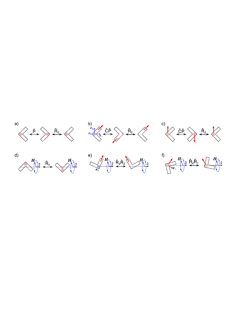
We apply the above symmetry arguments to planar V-shaped objects, schematically depicted in Fig. 1 and then test these predictions experimentally in Sec. VI. Note that the V-shape (ignoring its dipole moment) is a highly symmetrical object with two mutually perpendicular symmetry planes. In the frame of principal rotation axes aligned with eigenvectors of [see Fig. 1(b)] it therefore has only two nontrivial component of ( and ) prf17 .
Consider first a V-shaped structure with a magnetic moment oriented perpendicular to the plane of the object [see Fig. 1(a)]. This object is -even as well as -even. Denoting by rotation by around the th principal rotation axis, one can see that the object is mapped onto itself under , and . (Notice, however, that asymmetric V-shape with unequal arms is only -even.) When the magnetic moment lies in plane of the V-shape, e.g., directed along one of the arms as shown in Fig. 1(b), the object is -odd, but -even as maps it onto itself. The object in Fig. 1(c) with an off-plane orientation of the dipole, on the other hand, is odd under both and ; being invariant under it is -even.
Let us focus on the details of the propulsion. Fig. 1(e) illustrates the existence of two propulsive states related by the symmetry of a -even object. We assume arbitrary orientation of the V-shape with respect to the field so that its rotation could be accompanied by precession (or wobbling). As , the -symmetry implies that -rotation leads to another solution. Since inverts linear velocities, the two solutions have opposite propulsion velocities. As we shall demonstrate below, an individual -even objects can propel quite efficiently. The propulsion direction, - or , is controlled by the initial orientation which serves as to ‘spontaneously break the symmetry’. Thus a large collection of such propellers having random initial orientations would at most exhibit symmetric spreading with zero ensemble average velocity, as if it was a racemic mixture having an equal number of structures with opposite handedness. Notice that the symmetry arguments concerning the V-shaped object in Fig. 1(b) apply even if its two arms are unequal.
Similar arguments can be applied to the highly symmetric -even object with a permanent magnetic dipole as in Fig. 1a. A stronger result, however, can be obtained in this case combining symmetry and geometric arguments.
Although the shape of an arbitrary object can be infinitely complicated, in the low Reynolds-number regime we are guaranteed that its propulsion in the magnetic field is fully described in terms of a limited number of variables. Namely a (positive symmetric) tensor a pseudo-tensor (which w.l.o.g is also symmetric) and the pseudo vector (in the case of a permanently magnetized object). Moreover the rotational equations involve only and . These facts put further restrictions on the possible behavior of chiral objects. Notice that if instead of an object with permanent dipole we have a polarizable (i.e., superparamagnetic) object, then the analysis below has to be modified.
Let us first show that any -even magnetized object either has (implying it cannot propel upon rotation) or . To see this note that invariance under parity implies the existence of a rotation satisfying
The first relation implies that is diagonal in the frame of principal axes . If then from the second relation follows . Otherwise must be a rotation by around one of the principal axes and the third relation then demands to be along this axis. Note, moreover, that the relation with a -rotation around limits further the form of . If, e.g., it follows that only the elements , , can be nonzero.
Next we demonstrate that an object having along a principal axis, [e.g., along , as in Fig. 1(b )], will necessarily rotate around some other of its principal axes. To see this note that as is orthogonal to so must also be . As both and are also orthogonal to we conclude that they are parallel (unless ). The relation then implies that is an eigenvector of and hence coincides with one of the principal axes.
We further notice that an object undergoing planar precession-free rotation (tumbling) around a principal axis must also have the torque along this axis. Thus it implies that , and are all parallel to . Recalling that the net propulsion is also along the -axis, we find that (no summation) vanishes for any geometrically achiral shape, e.g., V-shaped object. In particular, neither of the two tumbling solutions shown in Fig. 1(d) and related by yield any net propulsion. Notice that for a symmetric V-shape, the solutions in Fig. 1(d) are invariant under which also proves that . However, our arguments are more general (they apply, e.g., to -even V-shape with unequal arms.)
Combining the above arguments it follows that -even magnetic swimmers with permanent dipole moment cannot propel. Furthermore, any geometrically achiral shape (such as V-shape), rotating around a principal axis in-sync with the actuating field will exhibit no net propulsion regardless of its symmetry, The net propulsion, in general, requires precession or wobbling of the object.
The finding that magnetized -even objects are unable to propel should be compared with the weaker result we had for a magnetized -even propellers [see Fig. 1(b),(e)] that can propel individually, while only the average velocity (over random initial orientations) needs to vanish. Notice also that the above reasoning only holds for structures with a permanent dipole. As we shall demonstrate below individual achiral (-even) polarizable objects can propel, as parity symmetry only guarantees vanishing of their ensemble average velocity.
Finally, the least symmetric (- and -odd) objects exhibit enantiomeric selection of the propulsion direction even when averaged over arbitrary initial orientation. This is illustrated for the V-shape in Fig. 1(c) with the magnetic moment, , lying in the plane orthogonal to . The two solutions shown in Fig. 1(f) can be related by the symmetry . As the V-shape is -even and applying yields another valid solution. Since (as opposed to and ) does not invert velocities, it guarantees that the two solutions possess the same propulsion velocity . Thus, the propulsion direction depends on the sense of rotation in exactly the same way as for left- or right-handed helices: the original object in Fig. 1(c) will translate along the field rotation -axis under clockwise (CW) rotation, while its -transformed enantiomer would propel in the opposite direction, regardless of the initial orientation. Notice that a collection of less symmetric (-odd) propellers, e.g., with unequal arms would still exhibit nonzero ensemble average velocity.
V Symmetries of electro-rotation solutions
Since an electric field acts on an electric dipole in exactly the same way that magnetic field acts on a magnetic dipole , one could imagine an electric propeller which is a complete analog of the magnetic one described above. This case differs from magnetic case described earlier in a number of aspects.
We first notice that the transformation properties of and under (, respectively) are exactly the same as the transformation properties of and under (, respectively). For a hypothetical object with permanent electric dipole actuated by a rotating electric field, one could apply the same arguments we had in the magnetic case using symmetry instead of (and vice versa). The conclusion would then also require merely a change of terminology everywhere.
Having a propeller with a permanent electric dipole is, however, not practically feasible and below (see Sec. VI) we present experiments involving polarizable structures with an induced electric dipole. Yet, some of the above arguments (that use the specific form of the governing equations) do not hold for polarizable (either electric or magnetic) propellers.
VI Experimental results
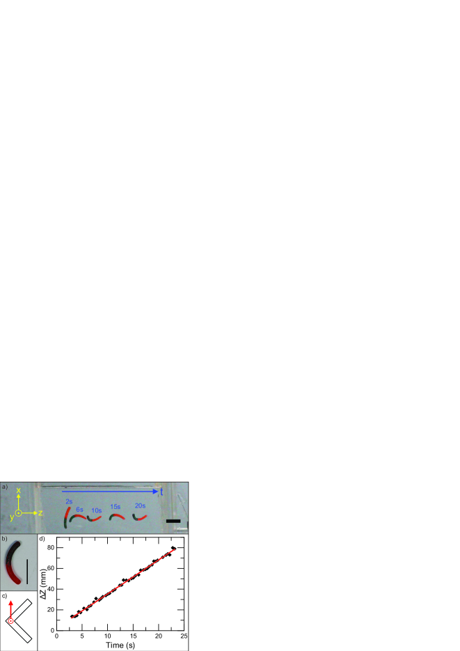
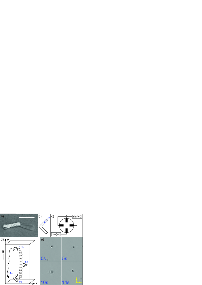
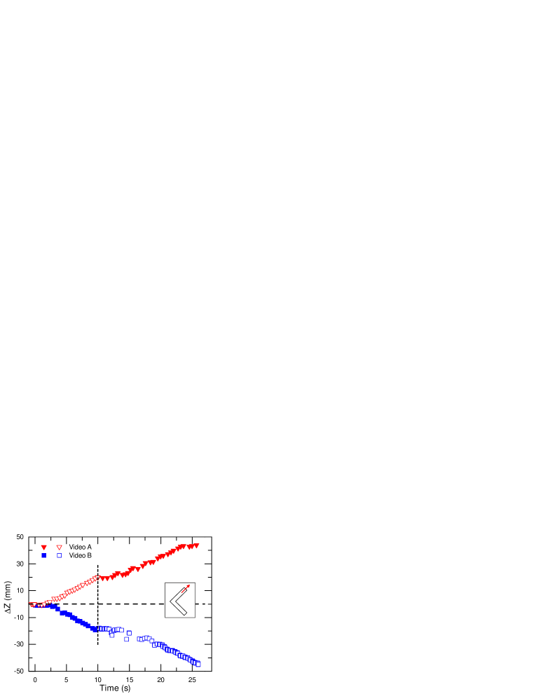
We now experimentally demonstrate the different propulsion gaits associated with different symmetries. We perform low-Reynolds-number experiments with cm-sized magnetic structures immersed in glycerol, as well as m-sized structures that possess either a magnetic or an induced electric dipole moment suspended in water. The larger objects allow for precise positioning and alignment of the magnetic moment. An arc-shaped structure with cross-sectional radius mm was 3D-printed [see Fig. 2(b)]. It had a cubic compartment into which a small 1 mm3 NdFeB (N45) ferromagnet was glued. The orientation of the magnet with respect to the object was therefore fixed and prescribed. The arc was placed in a cuvette filled with glycerol ( cP). The high viscosity prevented sedimentation and ensured that . A pair of two disk-shaped iron-based permanent magnets generated a homogeneous magnetic field of G throughout the volume of the cuvette. The magnets were mounted and mechanically rotated in the -plane around the cuvette. The driven motion of the arc was recorded and analyzed. Results for a right-handed arc with an off-plane magnetization [as in Fig. 1(c)] actuated by a rotating field at frequency of 1.5 Hz are shown in Fig. 2. In Fig. 2(a) the position and orientation of the arc is depicted at different times; Fig. 2(d) shows the corresponding displacement of the arc’s centerpoint along the -axis of the field rotation (see Video #1 SM ). The arc turns in-sync with the field and propels along the -axis, as expected for CW rotation.
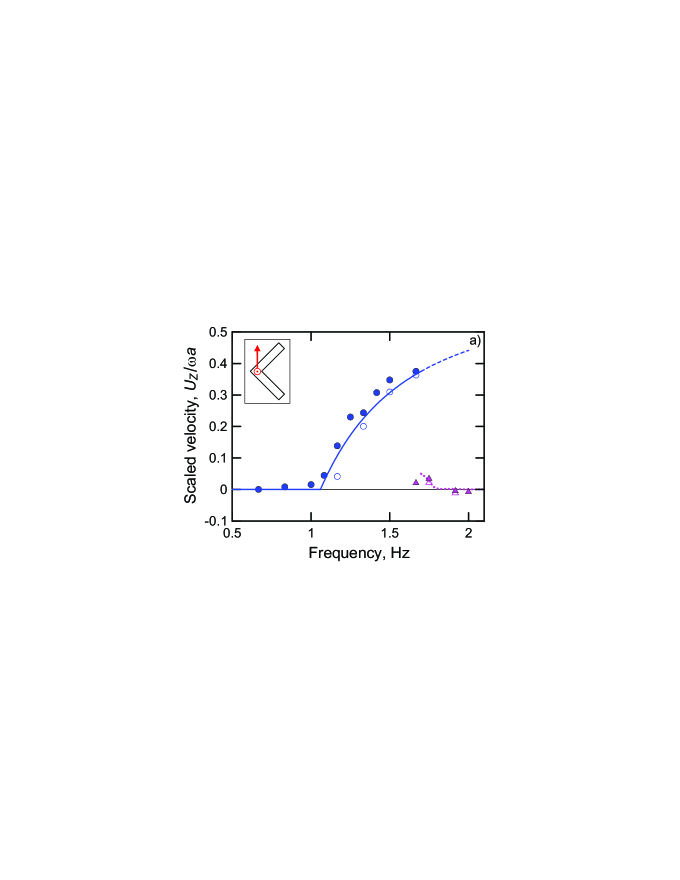
In Fig. 3(a) the scaled propulsion velocity of an off-plane magnetized (-odd) arc is depicted vs. the actuation frequency . At low frequencies Hz the arc tumbles without any noticeable translation. Above the tumbling-to-wobbling transition frequency, Hz, it starts to precess and propel along the -axis. The fact that propulsion occurs only at , demonstrates its dependence on dynamics rather than just symmetry. In Figs. 1(e, f) the non-propulsive tumbling regime corresponds to vanishing of the angle between and , that is precession-free rotation around . The regime selection at a given actuation frequency, i.e., non-propulsive tumbling vs. propulsive wobbling, depends on whether it is energetically more favorable for the angle between and to vanish or to have nonzero value. Such energy arguments were provided in ML14a assuming cylinder-like rotational anisotropy of the driven object. The direction of translation is controlled by the rotation sense of the applied magnetic field, thus the velocity of the structure in Fig. 3(a) is always positive. The velocity increases quasi-linearly with frequency, , similarly to a magnetic helix ML14a up to Hz in excellent agreement with the theory (see Appendices B and C). For frequencies Hz the arc can no longer turn in-sync with the external field and exhibits asynchronous twirling accompanied by a negligible net propulsion ML14a .
Note that while a combined rescaling of both and is expected to lead to a self-similar solution, the results presented here as a function of correspond to fixed value of which, e.g., sets the scale of , where is the transverse rotational mobility (see Appendix B). Thus no simple linear relation between and is expected.
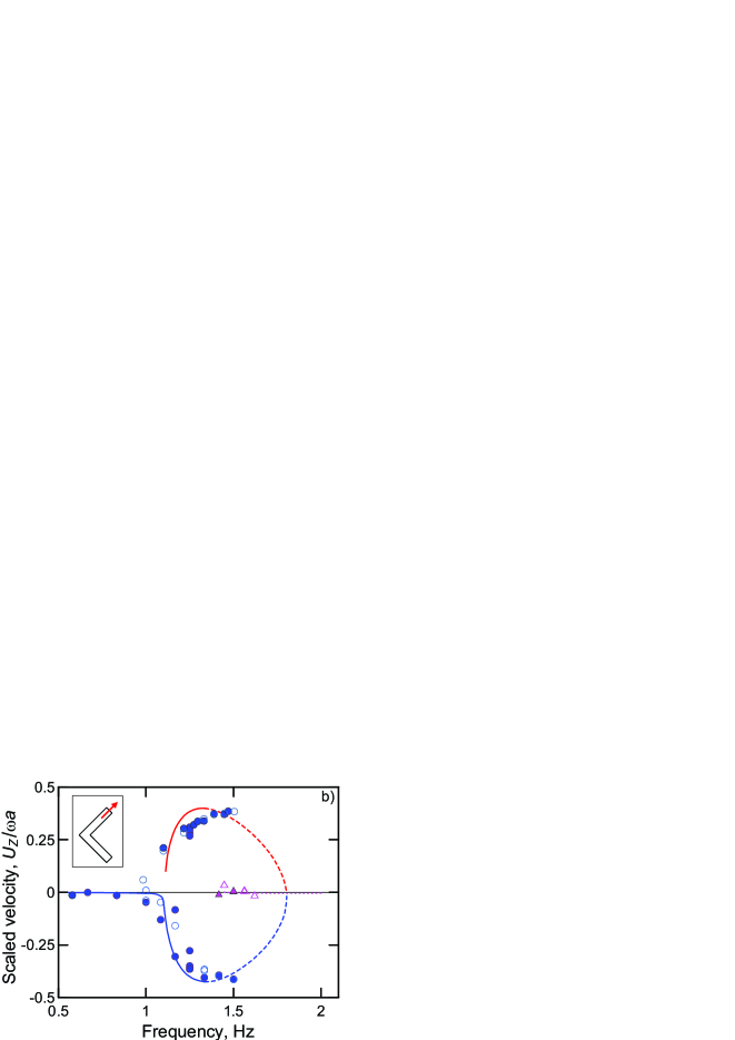
In Fig. 3(b) the velocity-frequency dependence is shown for an arc with a magnetic moment oriented along one of the arms. This (-even) structure can spontaneously break symmetry and exhibit translation when actuated at . Symmetry demands, however, that for every initial orientation of the structure propelling in one direction, there exists an orientation for which it will propel in the opposite direction as the symmetry transformed counterpart. The experimental results showing a symmetric pitchfork bifurcation in Fig. 3(b) (symbols) agree very well with the theory (see Appendices B and C) and the arc can propel in the direction irrespective of the sense of magnetic field rotation. It has also been confirmed experimentally (see Appendix D and Video #2 SM ) that upon reversal of the field rotation, the object maintains its propulsion direction. Additional experiments with the achiral arc magnetized along the principal rotation axes [e.g., Fig. 1(a)] have been performed demonstrating no propulsion, as expected (see Appendix E and Video #3 SM ).
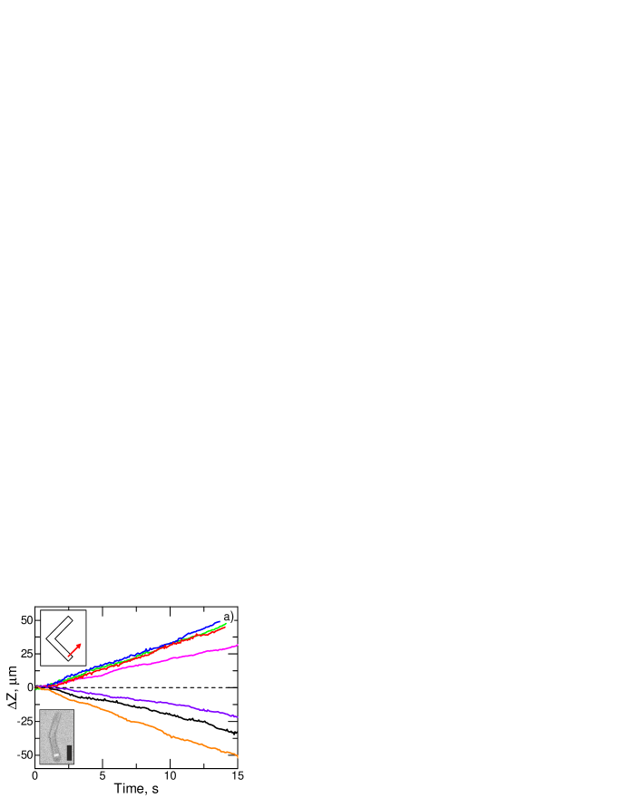
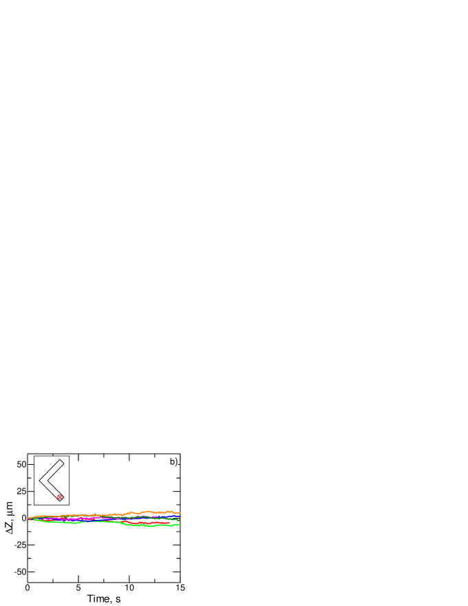
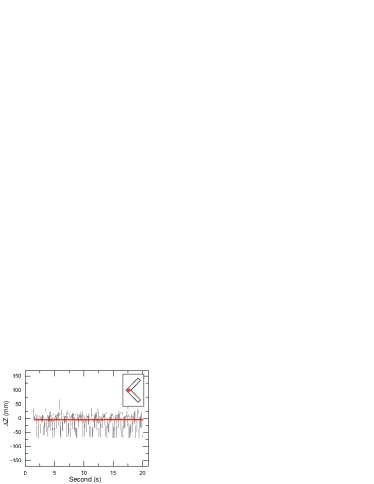
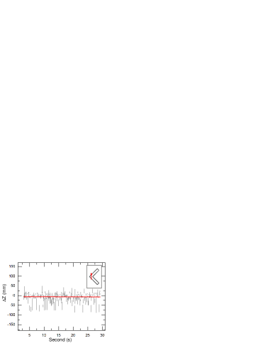
To demonstrate applicability of the symmetry considerations to the microscale objects, we used a physical vapor deposition method, known as glancing angle deposition (GLAD) to grow billions of magnetic microstructures on a wafer Robbie ; GF . V-shaped SiO2 microstructures containing a nickel section were grown onto silica beads (see SEM image in the inset in Fig. 4(a)). The growth direction is well-controlled during the GLAD process, which enables us to orient the V-shaped structures before they are magnetized. The desired magnetization was obtained by placing the wafer with the structures in an electromagnet (1.8 T) at a specific angle. Afterwards the V-shaped structures were removed from the wafer in an ultrasonic bath and dispersed in a solution of 150 M poly(vinylpyrrolidone). A custom 3-axis Helmholtz-coil setup was put up a microscope to generate a uniform magnetic field of G, rotating at a frequency of Hz in the -plane. Slight variation in the shape and the direction of magnetization of the colloids are expected. Two microstructures with symmetries shown in Fig. 1(a) and Fig. 1(b) were investigated and their translation along the -axis of the field rotation was measured. It is also possible to control the trajectory of the micropropellers by switching the external field rotation plane between all three principal planes, including, e.g., displacement out-of-focus of the microscope (see Appendix F and Video #4 SM ). In Fig. 4(a) the displacement of several -even structures is plotted vs. time. It can be seen that they move in opposite directions with approximately the same speed of m/s, which is about one body-length per second (see Video #5 SM ). On the other hand, as illustrated in Fig. 4(b), net propulsion of the achiral V-micropropellers is negligible as expected. These experimental observations are thus in agreement with the symmetry arguments above.
Finally, we demonstrate that propulsion can occur for structures of even higher symmetry. For that purpose we conducted experiment that involved polarizable structures with induced (rather than permanent) electric dipole. The GLAD technique was applied to grow V-shaped SiO2-microstructures with one arm being coated with a thin layer of gold, as shown in in Fig. 5(a). Au is highly polarizable and should, therefore, give rise to an induced electric dipole moment , where is a tensorial polarizability. Due to the anisotropy of the Au patch the V-microstructure [see Fig. 5(b)] possesses an anisotropic polarizability , which tends to align the Au-coated arm parallel to the external rotating -field.
After sonication in deionized water the suspension was placed in a four-electrode setup as schematically shown in Fig. 5(c) (see also Appendix G. Applying sinusoidal out-of-phase potentials at the electrodes at 500 kHz results in a rotating AC electric field that exerts an electric torque on the V-shape, , where is a unit vector along the Au-arm, causing its electro-rotation Fan . The actuating AC frequency of kHz is definitely beyond the step-out which is typically some tens of Hz, and a slow quasi-steady aperiodic rotation is taking place. General symmetry arguments should, however, hold regardless of the actuation regime. The resultant propulsion of the polarizable V-microstructure (against gravity) is illustrated in Figs. 5(d), (e) (see also Appendix G and Video #6, SM ) and it obviously resembles the dynamics of the magnetic counterpart from above despite their different symmetries. In fact, this is the first time, to the best of our knowledge, that propulsion of truly achiral objects has been demonstrated.
The electrically polarizable V-micropropeller in Fig. 5(b) is clearly both - and -even. General symmetry arguments then imply only that every positive propulsion solution has a complementary solution of opposite propulsion. For the V-shape with permanent magnetic dipole moment [see Fig. 1(a)] it was shown further that such high symmetry excludes propulsion even in individual instances. This stronger result, however, relied on the explicit form of the equations of motion rather than just symmetry. The equations governing the dynamics of the polarizable electric V-shaped object are, in fact, similar to those governing the -even (-odd) magnetic propeller [see Fig. 1(b)], apart from the extra scalar factor .
VII Concluding remarks
To conclude, the shape of an object together with its dipole moment determines its symmetry. The dipole moment affixed to geometrically achiral planar shape can render it chiral. Such chiral objects with intrinsically broken symmetry can exhibit steady unidirectional propulsion, resembling that of a helix, when actuated by a rotating field. In general, however, there could be two distinct in-sync rotational solutions possessing different propulsion velocities. For certain highly symmetric objects (e.g., - and -even polarizable propellers) these two velocities average to zero, while individual structures can propel efficiently due to spontaneous symmetry breaking. The theoretical predictions are confirmed experimentally using macro- and microscopic planar magnetized V-shaped propellers driven by a rotating magnetic field.
Our symmetry considerations can be extended to other shapes and actuation schemes. For example, it is interesting to note how these results change upon adding a constant magnetic field along the -axis that breaks the -symmetry (ii), but preserves -symmetry (i). In such a case -even objects can acquire a nonzero ensemble average velocity. For instance, the V-shape swimmer with dipole moment oriented along the symmetry axis (-odd) can, in a certain frequency range, exhibit unidirectional propulsion. Recall that in a planar rotational magnetic field magnetization along any principal axis yielded . The -even object with permanent dipole along a principal axis can still be shown not to propel even when actuated by this less symmetrical field. Dynamics driven by a conical rotating magnetic field (i.e., superposition of a rotating and a constant fields) is, however, beyond the scope of the present paper and will be considered elsewhere.
Acknowledgement
This work was supported in part by the German-Israeli Foundation (GIF) via the grant no. I-1255-303.10/2014 (A.M.L. and P.F.), by the Israel Science Foundation (ISF) via the grant No. 1744/17 (A.M.L.), by the Israel Ministry for Immigrant Absorption (K.I.M.) and by the Deutsche Forschungsgemeinschaft (DFG) as part of the project FI 1966/1 (P.F). J.S. and P.F. thank Donglei Fan and Jianhe Guo for helpful comments regarding the electro-rotation experiments.
Appendix A Driven propulsion in a rotating magnetic field
We consider the propulsion of an arbitrary magnetic object driven by an external uniform magnetic field . At low Reynolds number an object’s translational and rotational velocities and depend linearly on the external torque exerted on it (as the external force vanishes).
| (A1) |
Here and are the coupling and rotation viscous mobility tensors, respectively. The triad of unit eigenvectors, of makes up the body-frame principal rotation axes. We fix their order such that the corresponding eigenvalues satisfy . For an arc (or any planar symmetric V-shape) the principal rotation axes are shown schematically in Fig. 6. The lab coordinates unit vectors are related to the body frame axes by a rotation matrix parameterized through the three Euler angles and . These Euler angles thus describe the instantaneous orientation of the object in the lab frame. The object’s magnetization in the body-frame is characterized by a polar angle and an azimuthal angle , such that the magnetic moment affixed to the body is given by , where we used the compact notation , , etc.

We are interested in the solutions in which object turns synchronously with the magnetic field, i.e., rotating about the -axis with angular velocity . This condition reduces the into the system of nonlinear equation for the three angles , and . One can show that this system can further be reduced to a fourth order polynomial equation in prf17 . There can be up to eight in-sync solutions to such an equation. Physically however only stable solution are of real relevance. The number of stable solutions is found to be at most two.
By symmetry the average velocity in an in-sync solution is in the -direction. It can be written in a compact covariant form as prf17
| (A2) |
where is a dimensionless chirality matrix given by the symmetric part of with being the characteristic length. It is most convenient to write the RHS of Eq. A2 in terms of the body frame components, where is fixed and expressed using the Euler angles as
Notice that the Euler angle defines the precession/wobbling angle between the easy-axis and the -axis of the field rotation. One can show that (in contrast to ) is independent of the choice of coordinate origin. Under rotation of coordinate frame it transforms as a (symmetric) pseudo-tensor.
Appendix B Approximate theory for the magnetic V-shape
For a V-shaped object (or, in fact, any object possessing two mutually orthogonal planes of reflection symmetry, e.g., the arc in Fig. 6) the only nonzero component of the chirality matrix in Eq. (A2) is with being the width of the shape and the two major eigenvalues of . Eq. (A2) then reduces to
| (B1) |
The Euler angles , and can be found in a simple closed form assuming cylinder-like rotational anisotropy of the object, i.e., , which is an accurate approximation for an arbitrary object (see scirob ). In such a case, the above mentioned fourth order polynomial equation in reduces to a quadratic equation. A cylinder-like object has two distinct well-defined regimes of in-sync rotation – tumbling, whereas the easy-axis rotates in the -plane of the field, and wobbling, whereas undergoes precession with respect to field rotation -axis). The explicit form of the tumbling at low frequencies, , is ML14a
| (B2) |
The frequency of the tumbling-to-wobbling transition is , where is the characteristic frequency, , with being the harmonic mean of the minor rotational mobilities, . At higher frequencies, , up to the step-out frequency with , there are two complementary wobbling rotational states prf17 :
| (B3) | |||
| (B4) |
and . These dual solutions reveal the bistable character of the rotational problem usually leading to different propulsion gaits of the object depending on the initial orientation. The substitution of Eqs. (B3), (B4) into eq. (B1) gives the closed-form expression for the in-sync propulsion velocity:
| (B5) | |||||
where .
Thus, Eq. (B5) gives the propulsion velocity of V-shaped magnetic object in the high-frequency domain, , assuming cylinder-like rotational anisotropy. In the low-frequency domain, , the propeller tumbles without translation. At frequencies above the step-out, , the object can no longer rotate in-sync with the field and the transition to the asynchronous regime takes place. During asynchronous rotation the propulsion velocity rapidly diminishes with increasing frequency. This regime is beyond the scope of the present paper. Depending on the orientation of an objects magnetization there are two distinct propulsion scenarios considered in detail in the main text. The first case corresponds to out-of-plane [OOP, e.g. Fig. 1(c) of the paper] magnetization, with and the second case to in-plane [IP, e.g. Fig. 1(b) of the paper] magnetization, with . Below we consider both these cases in detail.
Out-of-plane magnetization
When , there are two non-trivial components of the propeller magnetization – along the directions and as shown in Fig. 1(c) in the main text. In this case the dual rotational states results in the same propulsion gait with the velocity
| (B6) |
Thus, for positive values of the parameter the V-shape object with the magnetic component in the direction of [ as in Fig. 1(c)] moves in the direction (), i.e., similar to a left-handed helix. In contrast, the V-shaped object with the magnetic component pointing in the direction (), moves along the -axis () similarly to a right-handed helix. Due to the freedom in the choice of orientation of the principal axes of rotation we assume here and thereafter w.l.o.g. that and .
We emphasize again that this helix-like propulsion corresponds to both rotational branches of the solution, e.g, the right-handed object under clock-wise rotation (CW) of the external field can move in the direction by two different ways: the object easy-axis may acquire either an obtuse or acute angle with the field rotation -axis. In the scaled-up experiment the cm-sized arc’s two halves were painted in two different colors – red and green. In case of an OOP magnetization it was shown to propel with either the red or the green end forward.
In-plane magnetization
When , there are two in-plane magnetization components – along the and axes as shown in Fig. 1(b) in the main text. In this case the dual in-sync rotational states yield propulsion in opposite directions:
| (B7) |
This means that the two symmetric (in polar angle ) solution branches (B3) and (B4) result in propulsion with the same speed in opposite directions. In contrast to the OOP-magnetized V-shape, the IP-magnetized arc can propel either along the -axis of the field rotation or anti-parallel to it. Moreover, unlike the OOP-magnetization, the IP-magnetized V-shape always propels while keeping the same orientation (of ) with respect to the field, meaning that depending on the value of the azimuthal magnetization angle (or, respectively, ) it will move either with the red (or, respectively, the green) end forward regardless of the sense of the fields rotation (CW or CCW).
Appendix C Parameter estimates for the magnetic arc
In the experiments we used the cm-size propeller [see Fig. 2(b) of the paper] in the shape of a circular arc with the centerline radius mm, waist mm and central angle of . The mobility tensors were computed numerically using the particle-based multipole expansion method (see, e.g., Filippov for a detailed description). We found
| (C1) |
where is the fluid dynamic viscosity. The value of the pseudo-chirality coefficient is then . The transverse anisotropy parameter proves to be quite small, , suggesting that the above cylindrical approximation is in fact quite accurate. The longitudinal anisotropy parameter is and the the transverse rotational mobility . Using the values of Oe, emu, P for glycerol, and cm we can estimate the characteristic frequency as s-1.
Out-of-plane magnetization, Fig. 3(a) of the paper
The polar magnetization angle was and the azimuthal angle corresponding to a right-handed helix, resulting in . The estimated frequencies of the tumbling-to-wobbling transition and the step-out are s-1 and s-1, respectively, giving Hz and Hz. Substitution of the values into Eq. (B6) gives the propulsion velocity as a function of actuation frequency for the case of OOP magnetization of the V-shaped object:
| (C2) |
The experimental data points (, ) in Fig. 3a of the paper are in excellent agreement with the theoretical prediction in Eq. (C2) for frequencies Hz. Notice that stable in-sync rotation in the frequency interval Hz Hz does not materialize in the experiments. This is due to the fact that for frequencies Hz [dashed line in Fig. 3(a)] the basin of attraction in terms of initial orientations, of the in-sync solution, shrinks rapidly in size, while for Hz Hz [solid line in Fig. 3(a)] the solution converges to the steady-state for an arbitrary initial orientation (i.e., basin of attraction filling all space). We could not observe the stable solutions at Hz Hz, as it was not possible to smoothly vary the actuation frequency on-the-fly in the experiments. Due to the finite size of the cuvette we started each experiment from rest with the arc placed roughly at the center of the cuvette and the rotating field was switched on abruptly with a particular (fixed) frequency . At Hz, the aperiodic tumbling of the V-shape takes place (, ) in a complete agreement with the theoretical prediction (dotted line) based on numerical integration of the dynamical system of Eqs.(5)–(7) in prf17 , for the Euler angles using the above estimated parameters and the geometry of the arc.
In-plane magnetization, Fig. 3(b) of the paper
The polar angle of magnetization in this case was and the azimuthal angle was close to . The estimated parameters are , Hz and Hz. Substituting these values into Eq. (B7) gives the propulsion velocity of the V-shape object as a function of actuation frequency for the IP-magnetization:
| (C3) |
The Eq. (C3) represents two symmetric (with respect to the -axis) branches, however, in reality, perfect IP magnetization is hard to achieve. Best fits of the theory to the experiments [see , in Fig. 3(b)] suggest minor imperfection in the azimuthal magnetization angle, , resulting in a slight asymmetry between the two solution branches in (C3) shown in Fig. 3(b) by the continuous (blue and red) lines. The agreement between the theoretical prediction (solid colored lines) and the experimental results is very good. As anticipated by the theory, both branches are equally accessible upon CW and CCW actuation. As for the case of OOP-magnetization and for the same reason, the high-frequency stable in-sync solutions (dashed colored lines) is hard to realize in the experiments. Therefore aperiodic tumbling (, ) takes over before the step-out at Hz is attained. And as for the OOP magnetization, the theoretical prediction of the aperiodic tumbling based on numerical integration of the full dynamical system in prf17 (dotted line) shows excellent agreement with the experimental results. Notice that the measurements were taken over a whole day during which the temperature and humidity raised resulting in somewhat lower (about 40%) viscosity of the glycerol as the viscosity of the pure glycerol is quite sensitive to temperature and humidity. This change resulted in proportional increase of the characteristic (dimensional) tumbling-to-wobbling and step-out frequencies. Therefore, the values of frequencies of the afternoon measurements were down-scaled by a constant factor of to match the measurements taken in the morning hours.
Appendix D Dual solution, in-plane magnetized arc
The displacement in the direction for the IP-magnetized arc [as in Fig. 1(b) in the main text], is shown in Fig. 7 over time. The data was extracted from Video #2 SM , in which the direction of the field rotation was suddenly reversed () after the arc started to move with a constant steady velocity . Upon this reversal the arc tumbles for a few revolutions, before acquiring a constant velocity equal to in the same direction as before. Recalling that our direction was defined by this is, in fact, equivalent to a change of the sign of , whereas its absolute value is the same before and after the field reversal in both experiments ( mm/s). These field reversal experiments confirm unequivocally the theoretical prediction in Eq. (B7) that the propulsion direction of IP-magnetized arc is independent of the field rotation sense.
Appendix E Achiral magnetic arc
In Fig. 8 the displacement of the magnetic arc is plotted vs. time for two shapes shown in the respective insets. The data was extracted from Video #3 SM . In both cases the magnetic moment is oriented along one of the principal axes of rotation rendering the arcs - and -even and therefore truly achiral. Thus, their dynamics is precession-free resulting in no net propulsion. This is readily seen from the negligible slope of the linear fit (red lines). Notice that the step-out frequencies for the two arcs shown in Fig. 8 are different. The arc shown in the right panel has a step-out frequency of Hz compared to the one shown in the left panel with Hz.
Appendix F -odd, -even magnetic V-shaped microcolloids
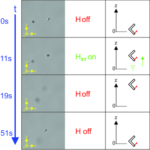
The Video #4 SM shows the ability to control the trajectory of the (-even, -odd) microcolloids by switching the external field rotation plane between all three principal planes. Notice that the -axis is now perpendicular to the microscope focal plane in contrast to the microcolloid experiments described in the main text (see Fig. 4), whereas the -axis belonged to the focal plane of the microscope. The frames in Fig. 9 correspond to a movement out-of-plane and were extracted at the specified times. They show the ability of -even V-shaped microsctructures can propel against gravity. One can see that the structure is in the microscopes’ focus at the beginning of the video and starts to move out-of-focus when the magnetic field is turned on in the -plane at 11 s. The magnetic field is then switched off at 19 s and the structure sediments and reappears in the focal plane of the microscope. Waiting even longer leads to further sedimentation and the image de-focuses again (not shown). This indicates that the trajectory of this microcolloid can be controlled in every spatial direction, including and .
Appendix G Achiral (-, -even) electrically polarizable V-shaped microcolloids
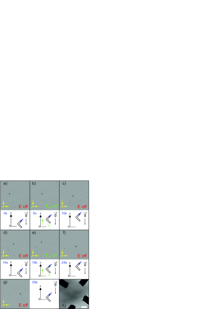
The same propulsion behavior as described in the previous section was demonstrated for a microcolloid driven by an electric instead of a magnetic field. This is shown in Video #6 SM , from which the frames shown in Fig. 10 were extracted; the -axis is now perpendicular to the focal plane of the microscope. The applied electric field strength was around kV/m with an AC frequency of kHz, while the V-shaped microstructures rotate with a few Hz as seen in the Video. It is obvious that the structure is initially at rest. As the AC electric fields starts to rotate in the -plane, the structure moves out-of-focus (along -direction). After switching off the electric field the structure sediments due to gravity. This sequence was repeated twice in a row. The behavior of the electric dipolar particle thus resembles the propulsion dynamics of the magnetic V-shaped microcolloid in Fig. 9, but this time with a truly achiral (i.e., - and -even) object. Notice that the magnetic analogue of such an achiral propeller in Fig. 1a in the main text does not propel. The electro-rotation of the structures is highly dependent on the geometry of the structure. Note that the visible drift in the -plane is most likely due to a small gradient of the electric field, as the four-electrode setup shows some asymmetry [see Fig. 10(h)].
Notes and references
- (1) L. Turner, W. S. Ryu and H. C. Berg, J. Bacteriol. 182, 2793 (2000).
- (2) A. Ghosh and P. Fischer, Nano Lett. 9, 2243 (2009).
- (3) L. Zhang, J. J. Abbott, L. Dong, B. E. Kratochvil, D. Bell and B. J. Nelson, Appl. Phys. Lett. 94, 064107, (2009).
- (4) E. M. Purcell, Am. J. Phys.45, 3 (1977).
- (5) M. Driscoll, B. Delmotte, M. Youssef, S. Sacanna, A. Donev and P. Chaikin, Nat. Phys. 13, 375 (2017).
- (6) Z. Lin, X. Fan, M. Sun, C. Gao, Q. He and H. Xie, ACS Nano 12, 2539 (2018).
- (7) E. J. Smith, D. Makarov, S. Sanchez, V. M. Fomin and O. G. Schmidt, Phys. Rev. Lett. 107, 097204 (2011).
- (8) D. Schamel, M. Pfeifer, J. G. Gibbs, B. Miksch, A. G. Mark and P. Fischer, J. Am. Chem. Soc., 135, 12353 (2013).
- (9) D. Schamel, A. G. Mark, J. G. Gibbs, C. Miksch, K. I. Morozov, A. M. Leshansky and P. Fischer, ACS Nano 8, 8794 (2014).
- (10) N. Baranova and B. Y. Zel’dovich, Chem. Phys. Lett. 57, 435 (1978).
- (11) M. Makino and M. Doi, Phys. Fluids 28, 093302 (2016).
- (12) M. Kostur, M. Schindler, P. Talkner and P. Hänggi, Phys. Rev. Lett. 96, 014502 (2006).
- (13) Marcos, H. C. Fu, T. R. Powers and R. Stocker, Phys. Rev. Lett. 102, 158103 (2009).
- (14) R. Eichhorn, Phys. Rev. Lett. 105, 034502 (2010).
- (15) R. Wittkowski and H. Löwen, Phys. Rev. E 85, 021406 (2012).
- (16) P. J. Vach, N. Brun, M. Bennet, L. Bertinetti, M. Widdrat, J. Baumgartner, S. Klumpp, P. Fratzl and D. Faivre, Nano Lett. 13, 5373 (2013).
- (17) P. J. Vach, P. Fratzl, S. Klumpp and D. Faivre, Nano Lett. 15, 7064 (2015).
- (18) U. K. Cheang, F. Meshkati, D. Kim, M. J. Kim and H. C. Fu, Phys. Rev. E 90, 033007 (2014).
- (19) K. I. Morozov, Y. Mirzae, O. Kenneth, and A. M. Leshansky, Phys. Rev. Fluids 2, 044202 (2017).
- (20) Y. Mirzae, O. Dubrovki, O. Kenneth, K. I. Morozov and A. M. Leshansky, Sci. Robot. 3, aas8713 (2018)
- (21) See Supplemental Material at http://link.aps.org/supplemental/… for videos.
- (22) J. Happel and H. Brenner, Low Reynolds Number Hydrodynamics (Kluwer, 1983).
- (23) L. D. Barron, Molecular Light Scattering and Optical Activity, 2nd edition (Cambridge University Press, 2004).
- (24) The possibility to classify solutions into -dual pairs related by may however be convenient sometimes..
- (25) Alternatively can be replaced by a -phase shift of the field, .
- (26) K. I. Morozov and A. M. Leshansky, Nanoscale 6, 1580 (2014).
- (27) K. Robbie, J. C. Sit and M. J. Brett, J. Vac. Sci. Technol. B 16, 1115 (1998).
- (28) A. G. Mark, J. G. Gibbs, T.-C. Lee, and P. Fischer, Nat. Mater. 12, 802(2013).
- (29) D. L. Fan, F. Q. Zhu, R. C. Cammarata, and C. L. Chien, Phys. Rev. Lett. 94, 247208 (2005).
- (30) A. V. Filippov, J. Colloid Interface Sci. 229, 184 (2000).
- (31) Notice that depending on slenderness of the V-shaped object the minor principal axes may be interchanged, prf17 .