Further author information:
S.J.: E-mail:
sjuodkazis@swin.edu.au, Telephone: +61 3 9214 87178
3D laser printing by ultra-short laser pulses for micro-optical applications: towards telecom wavelengths
Abstract
Three dimensional (3D) fast ( hour) printing of micro-optical elements down to sub-wavelength resolution over m footprint areas using femtosecond (fs-)laser oscillator is presented. Using sub-1 nJ pulse energies, optical vortex generators made of polymerised grating segments with an azimuthally changing orientation have been fabricated in SZ2080 resist; width of polymerised rods was nm and period 0.6-1 m. Detailed phase retardance analysis was carried out manually with Berek compensator (under a white light illumination) and using an equivalent principle by an automated Abrio implementation at 546 nm. Direct experimental measurements of retardance was required since the period of the grating was comparable (or larger) than the wavelength of visible light. By gold sputtering, transmissive optical vortex generators were turned into reflective ones with augmented retardance, defined by the form birefringence, , and the height where is the thickness of the polymerised structure. Retardance reached nm as measured with Berek compensator at visible wavelengths. Birefringent phase delays of (or in wavelength) required for high purity vortex generators can be made based on the proposed approach. Optical vortex generators for telecom wavelengths with sub-wavelength patterns of azimuthally oriented gratings are amenable by direct laser polymerisation.
keywords:
spin-orbit coupling, optical vortex, q-plates, laser polymerisation1 INTRODUCTION
Micro-optical elements and photonic wire bonding in telecom applications are becoming essential building blocks for imaging, surveillance, telecommunications, security, optical fiber, and sensor technologies [1]. Simplification of processing and fabrication steps is always recognisable in industrial innovations. In 3D nano-/micro-printing during last decade, we have seen emergence of new photo-materials tailored for laser fabrication using ultra-short sub-ps laser pulses. Different direct write, holographic exposure, nanoparticle-mediated modes of material modifications [2, 3, 4, 5, 6], formation of micro-channels in polymers and glasses [7, 8, 9], using different beam intensity profiles [10, 11] have been tested. Many remarkable results have been achieved with amplified femtosecond (fs)-laser systems at lower laser repetition rates when thermal effects, usually not desirable, can be avoided. However, even simpler solutions are available using only fs-laser oscillators with pulse energies of nJ at high repetition rate of MHz and allow harnessing of photo-thermal effects which delivers more control in 3D laser ablation [12] and polymerisation. By fast beam scanning, it is possible to reach a high sub-wavelength resolution and practical fabrication times of micro-optical elements with sub-mm cross sections demonstrated in this study and not possible to achieve with low repetition rate fs-laser systems [9].
Here, we show 3D fabrication of flat optical elements by using only fs-laser oscillator over area of 0.1 mm in cross section. High fidelity fabrication was achieved with uniform height of the optical vortex generators chosen to belong to the family of the so-called q-plates. The q-plates are birefringent patterns (here form-birefringent) whose slow-optical axis has a local azimuthal angular orientation defined by the azimuth with being half-integer [13, 14, 15]. They can be realised by different fabrication and patterning methods [13, 16, 17, 18, 19, 20, 21, 22] and allow polarisation controlled management of the orbital angular momentum. Birefringent phase retardance of has been achieved (at visible wavelengths) for the reflection-type q-plates using one layer fabrication. This fabrication is simpler as compared with q-plates polymerised using direct writing with amplified fs-laser system [23]. Optical characterisation of form-birefringent flat optical elements was carried out to inspect structural quality of patterns, which are sub-wavelength for the telecommunication wavelengths where flat optical elements for generation of optical vortex beams carrying orbital angular momentum (OAM) are under active exploration due to possibility to reach high data transfer densities.
2 Experimental
2.1 Fabrication of q-plates
Mai Tai (Spectra Physics) fs-laser oscillator emitting 800 nm wavelength, 120 fs duration pulses was used as a light source for direct laser writing. The pulses were focused into the photoresist through a microscope cover glass substrate using a microscope objective lens (Olympus, UPlanSApo 60×/1.35 Oil) with numerical aperture . During the direct laser writing the sample was scanned by a 3D piezo-stage (Physik Instrumente, P-563.3CD) with xy-(in-plane) stroke of m and z-axis (axial) stroke of 250m. Typical writing speed was m/s. High pulse repetition rate of 80 MHz ensured that focal area of diameter m was exposed to millions of laser pulses. Circularly polarised laser beam was used in experiments in order to equalize lateral diameter of polymerised voxels and obtain lines, whose width does not depend on the orientation [24]. The initial focusing plane for fabrication was chosen by adjusting the z-axis position within m accuracy window. The empirical procedure to find glass substrate/photoresist interface involved determination of z-axis position at which brightness of two-photon excited photoluminescence emitted by the photoinitiator reached half of its maximal value. The experimental system used for fabrication ensured that z-axis position was maintained stable from within few tens of minutes to hours, which provided sufficient time for sample fabrication. However, random drifts of the z-axis position by up to 1m also occurred occasionally, which led to line height and retardance variation across the area of q-plate, and degraded optical quality of some samples. Precise origin of this drift has not yet been determined, although it is likely related to thermal deformation of metallic parts in the setup, and to capillary drag of the moving sample by the oil-immersion lens.
The negative-tone Zr-containing hybrid organic-inorganic photoresist SZ2080 with only 0.5% of Irgacure 369 (2-Benzyl-2-dimethylamino-1-(4-morpholinophenyl)-butanone-1) and (Irg) and Michler’s ketone 4,4’-Bis (diethylamino) benzophenone (Bis) was added as photo initiators. Low concentration of photo initiator reduces an optical absorption at the visible spectral range and, consequently, reduces dichroism of form-birefringent q-plates which are inherently spectrally broad band optical elements, though at the expense of wavelength-dependent efficiency. The q-plates were prepared by drop-casting photoresist on a microscope cover glass substrates (Matsunami) and subsequently drying them on a hot plate using temperature ramp (for 5 min) between 40, 60, and 80∘C for 20 min. After laser exposure, the samples were developed in 1-propanol:isopropanol (50:50) solution for 5 min., rinsed in ethanol, and dried in super-critical CO2 using a critical-point dryer (JCPD-5, JEOL), in order to eliminate destructive action of capillary forces during conventional drying.
2.2 Characterisation of q-plates
Retardance of form-birefringent q-plates [nm] was measured using Berek compensator No. 10412 (Nichika, Co. Ltd.) setup on a Nikon Optiphot-Pol microscope and by using manual alignment; is the birefringence and is an optical path length. Calcite compensator plate is inserted at 45∘ to the crossed analyser-polariser orientation along the slow axis of the extraordinary refractive index ; calcite is the negative uniaxial material . Then, by tilting the compensator plate clockwise and anti-clockwise, a selected and aligned form-birefringent region of q-plate was made darkest (the lowest transmission); the orientation along the polymerised grating of the q-plate was aligned with orientation of the Berek compensator. The average angle between two settings was used to find the retardance using tabulated reference. Also, an Abrio attachment to Nikon microscope was used to determine the birefringence (retardance) and orientation of the optical fast-axis at 546 nm wavelength. This measurement is carried out automatically and was compared with manual measurements with Berek compensator. These two different methods were applied in collaborating labs in Bordeaux and Tokyo and calibrated using commercial quarter-waveplates of the known phase retardance.
3 Results
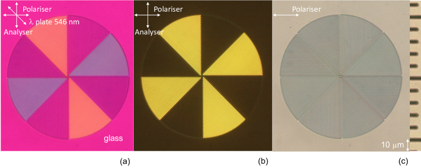
Figure 1 shows different optical images of plate which reveal a high quality and uniformity of the polymerised structure. By inserting a 530 nm waveplate at 45∘ orientation into cross-polarised imaging setup, a color shift helps to reveal even better settle changes in the phase retardance. The close up view (Fig. 1(a)) shows the darker regions where SZ2080 polymerised logs were fabricated and color tint almost reaches that of the substrate’s between the logs (an air gap region). Hence, there is the same light phase at the bottom between the logs and glass substrate surface. Such imaging provides a detailed assessment of birefringent phase delay at different locations of this form-birefringent structure and is valuable due to limitations of the effective medium theory (EMT) predictions which are only valid for patterns with period much smaller than the wavelengths of the light . In this particular case m while the nm, obviously out of validity range of EMT.
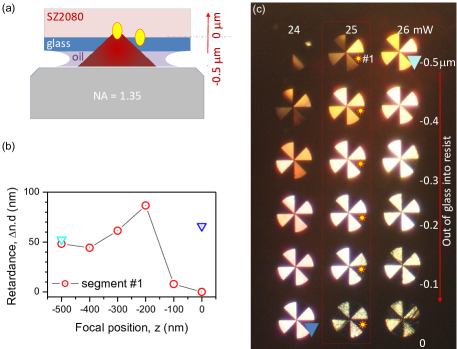
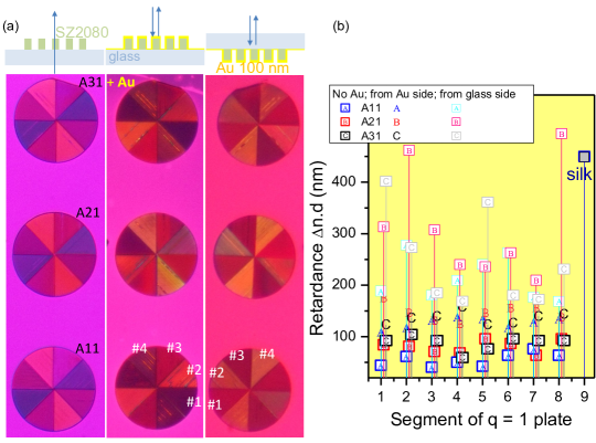
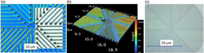
Figure 2 provides optical profilometry of the q-plate which has period m and height of m for the width of polymerised logs nm. Even high duty-cycle could be fabricated using such conditions with air gap of 150 nm. The pattern over 0.1 mm-diameter was fabricated with high fidelity over a practical time span of 30 min. The start and stop points were overexposed what caused thickening of rods. This can be removed using a more sophisticated shutter control which was not implemented in this first fabrication.
Figure 3 shows dependence of retardance as depth of focusing was changed (along z-axis; see panel (a)). The structural quality easily distinguishable from optical images correlated with the retardance, which reached the highest values for the tallest patterns (Fig. 3(b)). These q-plates (Fig. 3(c)) have period of m and duty cycle close to 0.5.
| Sample | Transmission | Reflection from Au-side | Reflection from Au through substrate |
| (nm): | (nm): | (nm): | |
| A11 | 55.3 | 127.8 | 213.0 |
| A21 | 80.9 | 148.0 | 315.7 |
| A31 | 88.0 | 135.9 | 246.7 |
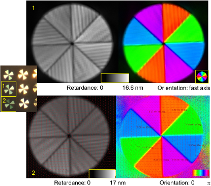
By evaporating 100 nm film of gold directly over q-plate, the optical transmission is blocked. In reflection mode, there is a benefit of doubling the optical path length , which increases retardance . Moreover, by measuring retardance in reflection from the q-plate side this doubling take place in air while by flipping the sample and measuring from the glass side allows to double the optical path in SZ2080 portion of the q-plate (see schematics on top of Fig. 4(a)). The color-shifted cross-polarised images of the described above three modes with different retardance are gathered in Fig. 4(a).
Measurements of retardance with Berek compensator at each segment (eight per q-plate) are summarised in Fig. 4(c) and the average is presented in Table 1. Quite large data scatter was observed. For comparison, retardance of a single silk fiber was also measured (diameter m) with birefringence found , which is typical to silk (Fig. 4(b)). Since the measurements were carried out with Berek’s compensator aligned along the silk fiber (alignment along fast axis of the compensator) a positive retardance is consistent with a larger refractive index of silk for the E-field polarised along the fiber.
As fabricated q-plates had an average (over 8 segments) retardance of 55.3 nm (A11), 80.9 nm (A21), and 88.0 nm (A31) summarised in Table 1. When measured in reflection from the gold deposited side, retardance increased by 2.31 for A11, by 1.83 for A21, and by 1.54 for A31. The highest values were obtained for the reflection measurements from the substrate side with further increase by 1.67 (A11), by 2.13 (A21), and by 1.82 (A31); the increase is compared with the reflection case from the q-plate side. These values are already larger than or in terms of the phase delay. These retardance increases are approximately scaling as ( is the refractive medium) and reach factor of for the reflection from the substrate side as expected. Since , this experimental observation provides a direct measurement which cannot be obtained by EMT modeling. Due to a manual nature of measurements with Berek compensator, there is a considerable scatter of results due to a visual judgement for the darkest segments.
A simpler solution of reflective q-plate was realised by Au-evaporation on the back-side of substrate (not on the q-plate as discussed above). Doubling of retardance was achieved, however, a strong hallo effects, i.e., a wide area of leaking illumination through cross polariser-analyser setup was observed around the q-plate area. This is caused by scattering and redirection of light as it traverses twice through the entire thickness of cover glass m and q-plate.
The manually measured retardance with the Berek compensator under white light illumination was compared with an automatic equivalent compensator based on light crystal compensator (Abrio) at 546 nm wavelength. Figure 5 shows retardance and orientation of slow-axis along the ordinary refractive index in the form-birefringent negative uniaxial pattern of the two selected q-plates. High quality and uniformity of the pattern is confirmed for the height as well as orientation over the entire area of the q-plates. In order to compare retardance measurements with two different compensators Berek and Abrio, the waveplates for 530 nm and 532 nm wavelength were carried out using setups located in Tokyo and Bordeaux, respectively. For Berek (Tokyo), retardation value was nm (10 measurements) under white light illumination. For Abrio (Bordeaux), the measured retardance of 132.4 nm was smaller than the theoretical value for the 0-order 532 nm waveplate (measured at 546 nm). The Berek measurements carried out manually over entire white light spectrum were by larger than the theoretically expected value. The values summarised in Table 1, which were measured with Berek compensator, can have an approximately over-estimate, which is acceptable for the manual spectrally broad-band measurement of the retardance.
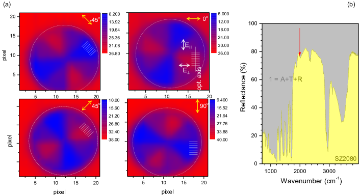
Figure 6(a) shows reflectance of q-plate at IR 5 m wavelength at four polarisations and (b) shows its spectrum. The height of the gratings constitutes only at this mid-IR wavelength (Fig. 2). Dichroic losses are usually measured in transmission for two linearly polarised beam orientations , where are the transmitted power parallel and perpendicular to the local optical axis, respectively. It can be applied for the reflectance as well, e.g., for the orientation (Fig. 6(a)) the ratio gives or rad at m wavelength. Following a general definition with being the phase retardance and dichroism for the height of q-plate along the light propagation length at wavevector and wavelength .
The anisotropy of absorbance, , can be determined from the angular dependence of and only four angles with angular separation of are required to make the fit [25]:
| (1) |
where are the absorbances parallel and perpendicular to the local optical axis, respectively, is the azimuthal angle. For the complex refractive index , the oscillating E-field of light can be written as a function of height, , as , where is the angular frequency and is speed of light. The amplitude of the E-field decreases exponentially with high, i.e., the intensity is given by the Lambert-Beer’s law , where is the absorption coefficient. Then, the amplitude, , of the -wave-form measured by the 4-polarisation method (Eqn. 1) is related to the dichroism as:
| (2) |
4 Discussion
For the case when the period of structure is comparable to the wavelength, , analytical methods to calculate effective refractive index by EMT approach lose validity [26, 27] and direct measurements of retardance should be carried out. The measured retardance of flat optical elements made of azimuthally oriented segments of gratings with 0.6, 1 m period and a duty-cycle close to 0.5, shows that the phase retardance can be controlled with high precision and a value can be made in reflection over the entire visible spectral range. Taller polymerised structures would be required to make waveplates (with phase retardance) in transmission, also, for longer IR-wavelengths. For telecom spectral range around m, taller structures could be fabricated with the periods in sub-wavelength range (similar to that used in this study). Higher aspect ratio 3D polymerised structures are in reach for fs-laser polymerisation, especially, when critical point dryer (CPD) is used to retrieve fabricated and developed sample from a rinse solution. By avoiding capillary forces in super-critical CO2, it is possible to recover 3D patter ns with intricate 100 nm feature sizes without mechanical failure [1].
For q-plates with lower than retardance in phase there is a possibility to separate the optical vortex beam which carries OAM from the non-vortex part. Q-plates are irradiated with a circularly polarised beam which carries a defined spin angular momentum (SAM) and the vortex beam with (OAM) generated via spin-orbital coupling in q-plate has a counter-circular SAM. By separation of left and right circular polarised beams it is possible to use vortex generation at a cost of lower efficiency.
The efficiency and purity of vortex generation are discussed next. Transmittance for E-field accounts for the losses, hence, defines the overall transmittance; intensity . The electric field emerging through the q-plate, , is given [28]:
| (3) |
where the incident field is circularly polarised with and defining the left and right-handed polarisations in the Cartesian frame, respectively. At the given transmittance, the spin-orbital coupling efficiency is determined by the dichroism and birefringence properties of the material and is maximised for the half-wavelplate condition of the q-plate: modulo .
The purity of the spin-orbital conversion is defined by parameter , which is the fraction of the output power that corresponds to helicity-flipped field expressed as [29]. Interestingly, the dichroism may enhance or reduce the purity depending on the real birefringent phase retardation [23]. At the half-waveplate condition , when dichroic losses are absent . Dichroic losses are measured for the plate (a grating) for two linearly polarised beam orientations as shown above. The vortex generation efficiency is .
5 Conclusions and outlook
High-quality sub-1 mm flat micro-optical elements based on a geometrical phase realised by azimuthally orientated grating segments down to resolution of nm are demonstrated. Laser writing using only fs-laser oscillator took only 0.5 hours to fabricate entire optical element and this is a simpler solution compared with polymerisation of spiral plate [30]. An increase of retardance using optical path doubling in reflection mode allowed to achieve phase control required for high purity of optical converters which turn circular polarisation (a spin angular momentum) of an incoming light into counter-circularly polarised optical vortex (a beam with the orbital angular momentum). Such planar optical vortex generators can find applications in optical manipulation, microfluidics, and sensing [31, 32, 33]. Sub-wavelength period gratings at telecommunication spectral window 1.3-1.5 m can be made using the proposed method.
Other strategies to obtain reflective optical vortex generators based on spin-orbit optical interactions using chiral and anisotropic media have recently been introduced [34, 35, 36].
Acknowledgements.
We are grateful to Fujii-san from Nichika, Co. Ltd. for providing us (within the same day of inquiry) with a calibration curve of the Berek compensator No. 10412 which was purchased by Tokyo Institute of Technology in around 1995. J.M. acknowledges partial support by the Kakenhi No. 16K06768 grant, S.J. was partially supported by the NATO grant SPS-985048 and the Australian Research Council DP170100131 Discovery Projects. Research visit of S.J. to Tokyo Institute of Technology was supported via the Australian Academy of Science and JSPS fellowship scheme in 2016.References
- [1] M. Malinauskas, A. Žukauskas, S. Hasegawa, Y. Hayasaki, V. Mizeikis, R. Buividas, and S. Juodkazis, “Ultrafast laser processing of materials: from science to industry,” Light: Sci. Appl. 5(8), p. e16133, 2016.
- [2] T. Kondo, S. Juodkazis, V. Mizeikis, S. Matsuo, and H. Misawa, “Fabrication of three-dimensional periodic microstructures in photoresist SU-8 by phase-controlled holographic lithography,” New J. Phys. 8(10), p. 250, 2006.
- [3] K. K. Seet, V. Mizeikis, S. Juodkazis, and H. Misawa, “Three-dimensional horizontal circular spirals photonic crystals with stop gaps below m,” Appl. Phys. Lett. 88(22), p. 221101, 2006.
- [4] K. Ueno, S. Juodkazis, T. Shibuya, V. Mizeikis, Y. Yokota, and H. Misawa, “Nano-particle-enhanced photo-polymerization,” J. Phys. Chem. C 113(4), pp. 11720–11724, 2009.
- [5] N. Murazawa, K. Ueno, V. Mizeikis, S. Juodkazis, and H. Misawa, “Spatially selective non-linear photopolymerization induced by the near-field of surface plasmons localized on rectangular gold nanorods,” J. Phys. Chem. C 113(4-6), pp. 1147 – 1149, 2009.
- [6] A. Žukauskas, M. Malinauskas, A. Kadys, G. Gervinskas, G. Seniutinas, S. Kandasamy, and S. Juodkazis, “Black silicon: substrate for laser 3D micro/nano-polymerization,” Optics Express 21(6), pp. 6901–6909, 2013.
- [7] S. Juodkazis, K. Yamasaki, V. Mizeikis, S. Matsuo, and H. Misawa, “Formation of embedded patterns in glasses using femtosecond irradiation,” Appl. Phys. A 79(4-6), pp. 1549 – 1553, 2004.
- [8] K. Yamasaki, S. Juodkazis, S. Matsuo, and H. Misawa, “Three-dimensional microchannels in polymers: one step fabrication,” Appl. Phys. A 77, pp. 371–373, 2003.
- [9] S. Juodkazis, S. Matsuo, H. Misawa, V. Mizeikis, A. Marcinkevicius, H. B. Sun, Y. Tokuda, M. Takahashi, T. Yoko, and J. Nishii, “Application of femtosecond laser pulses for microfabrication of transparent media,” Appl. Surf. Sci. 197-198, pp. 705–709, 2002.
- [10] E. Gaižauskas, E. Vanagas, V. Jarutis, S. Juodkazis, V. Mizeikis, and H. Misawa, “Discrete damage traces from filamentation of Bessel-Gauss pulses,” Opt. Lett. 31(1), pp. 80–82, 2006.
- [11] A. Marcinkevicius, S. Juodkazis, S. Matsuo, V. Mizeikis, and H. Misawa, “Application of Bessel beams for microfabrication of dielectrics by femtosecond laser,” Jpn. J. Appl. Phys. 40(11A), pp. L1197–L1199, 2001.
- [12] E. Vanagas, I. Kudryashov, D. Tuzhilin, S. Juodkazis, S. Matsuo, and H. Misawa, “Surface nanostructuring of borosilicate glass by femtosecond nJ energy pulses,” Appl. Phys. Lett. 82(17), pp. 2901–2903, 2003.
- [13] G. Biener, A. Niv, V. Kleiner, and E. Hasman, “Formation of helical beams by use of Pancharatnam - Berry phase optical elements,” Opt. Lett. 27, pp. 1875 – 1877, 2002.
- [14] L. Marrucci, C. Manzo, and D. Paparo, “Optical spin-to-orbital angular momentum conversion in inhomogeneous anisotropic media,” Phys. Rev. Lett. 96, p. 163905, 2006.
- [15] S. Slussarenko, A. Murauski, T. Du, V. Chigrinov, L. Marrucci, and E. Santamato, “Tunable liquid crystal q-plates with arbitrary topological charge,” Opt. Express 19, pp. 4085–4090, 2011.
- [16] Y. Shimotsuma, P. G. Kazansky, J. Qiu, and K. Hirao, “Self-organized nanogratings in glass irradiated by ultrashort light pulses,” Phys. Rev. Lett. 91, p. 247405, 2003.
- [17] E. Karimi, S. A. Schulz, I. De Leon, H. Qassim, J. Upham, and R. W. Boyd, “Generating optical orbital angular momentum at visible wavelengths using a plasmonic metasurface,” Light Sci Appl 3, p. 4, 2014.
- [18] G. Li, M. Kang, S. Chen, S. Zhang, E. Y.-B. Pun, K. W. Cheah, and J. Li, “Spin-enabled plasmonic metasurfaces for manipulating orbital angular momentum of light,” Nano Lett 13(9), pp. 4148–4151, 2013.
- [19] J. Jin, J. Luo, X. Zhang, H. Gao, X. Li, M. Pu, P. Gao, Z. Zhao, and X. Luo, “Generation and detection of orbital angular momentum via metasurface,” Sci. Reports 6, p. 24286, 2016.
- [20] R. C. Devlin, A. Ambrosio, D. Wintz, S. L. Oscurato, Z. A. Yutong, M. Khorasaninejad, J. Oh, P. Maddalena, and F. Capasso, “Spin-to-orbital angular momentum conversion in dielectric metasurfaces,” e-prints ArXiv :1605.03899 , p. arXiv, 2016.
- [21] S. Kruk, B. Hopkins, I. I. Kravchenko, A. Miroshnichenko, D. N. Neshev, and Y. S. Kivshar, “nvited article: Broadband highly efficient dielectric metadevices for polarization control,” Appl. Phys. Lett.: Photonics 1, p. 030801, 2016.
- [22] S. M. Kamali, E. Arbabi, A. Arbabi, Y. Horie, and A. Faraon, “Highly tunable elastic dielectric metasurface lenses,” Laser Photn. Rev. 10, p. DOI: 10.1002/lpor.201600144, 2016.
- [23] X. Wang, A. A. Kuchmizhak, E. Brasselet, and S. Juodkazis, “Dielectric geometric phase optical elements fabricated by femtosecond direct laser writing in photoresists,” Appl. Phys. Lett. 110(18), p. 181101, 2017.
- [24] S. Rekštytė, T. Jonavicius, D. Gailevičius, M. Malinauskas, V. Mizeikis, E. G. Gamaly, and S. Juodkazis, “Nanoscale precision of 3D polymerisation via polarisation control,” Adv. Opt. Mat. 4(8), pp. 1209 – 1214, 2016.
- [25] Y. Hikima, J. Morikawa, and T. Hashimoto, “FT-IR image processing algorithms for in-plane orientation function and azimuth angle of uniaxially drawn polyethylene composite film,” Macromolecules 44(10), pp. 3950 – 3957, 2011.
- [26] M. Born and E. Wolf, Principles of Optics: Electromagnetic Theory of Propagation, Interference and Diffraction of Light, Cambridge University Press, Cambridge, 7 ed., 2002.
- [27] A. Emoto, M. Nishi, M. Okada, S. Manabe, S. Matsui, N. Kawatsuki, and H. Ono, “Form birefringence in intrinsic birefringent media possessing a subwavelength structure,” Appl. Opt. 49(23), pp. 4355 – 4361, 2010.
- [28] D. Hakobyan, H. Magallanes, G. Seniutinas, S. Juodkazis, and E. Brasselet, “Tailoring orbital angular momentum of light in the visible domain with metallic metasurfaces,” Adv. Opt. Mater. 4, pp. 306 – 312, 2016.
- [29] D. Hakobyan, Spin-orbit optomechanics of space-variant birefringent media. PhD thesis, University of Bordeaux and Swinburne University of Technology, 2016.
- [30] E. Brasselet, M. Malinauskas, A. Žukauskas, and S. Juodkazis, “Photo-polymerized microscopic vortex beam generators : precise delivery of optical orbital angular momentum,” Appl. Phys. Lett. 97, p. 211108, 2010.
- [31] H. Misawa and S. Juodkazis, “Photophysics and photochemistry of a laser manipulated microparticle,” Prog. Polym. Sci. 24, pp. 665–697, 1999.
- [32] E. Brasselet and S. Juodkazis, “Optical angular manipulation of liquid crystal droplets in laser tweezers,” J. of Nonlin. Opt. Phys. and Mat. 18(2), pp. 167–194, 2009.
- [33] Y. Nishijima, K. Ueno, S. Juodkazis, V. Mizeikis, H. Misawa, H. Tanimura, and K. Maeda, “Inverse silica opal photonic crystals for optical sensing applications,” Opt. Express 15(20), pp. 12979–12988, 2007.
- [34] M. Rafayelyan, G. Tkachenko, and E. Brasselet, “Reflective spin-orbit geometric phase from chiral anisotropic optical media,” Phys. Rev. Lett. 116, p. 253902, 2016.
- [35] M. Rafayelyan and E. Brasselet, “Bragg-Berry mirrors: reflective broadband q-plates,” Opt. Lett. 41(17), pp. 3972 – 3975, 2016.
- [36] J. Kobashi, H. Yoshida, and M. Ozaki, “Polychromatic optical vortex generation from patterned cholesteric liquid crystals,” Phys. Rev. Lett. 116, p. 253903, 2016.