Present address: ]Condensed Matter Group, National High Magnetic Field Laboratory, Florida State University, Tallahassee, Florida 32310, USA
Investigation of the commensurate magnetic structure in heavy fermion CePt2In7 using magnetic resonant X-ray diffraction
Abstract
We investigated the magnetic structure of the heavy fermion compound CePt2In7 below K using magnetic resonant X-ray diffraction at ambient pressure. The magnetic order is characterized by a commensurate propagation vector with spins lying in the basal plane. Our measurements did not reveal the presence of an incommensurate order propagating along the high symmetry directions in reciprocal space but cannot exclude other incommensurate modulations or weak scattering intensities. The observed commensurate order can be described equivalently by either a single- structure or by a multi- structure. Furthermore we explain how a commensurate-only ordering may explain the broad distribution of internal fields observed in nuclear quadrupolar resonance experiments (Sakai et al. 2011, Phys. Rev. B 83 140408) that was previously attributed to an incommensurate order. We also report powder X-ray diffraction showing that the crystallographic structure of CePt2In7 changes monotonically with pressure up to GPa at room temperature. The determined bulk modulus GPa is similar to the ones of the Ce-115 family. Broad diffraction peaks confirm the presence of pronounced strain in polycrystalline samples of CePt2In7. We discuss how strain effects can lead to different electronic and magnetic properties between polycrystalline and single crystal samples.
pacs:
75.25.-j, 75.30.Mb, 61.05.cpI Introduction
Electrons can gain a large effective mass due to strong electronic correlations in crystals. Such materials are referred to as heavy fermion compounds and often have complex phase diagram due to the interplay of spin and electronic degrees of freedom. Of particular interest are the Ce-115 compounds CeMIn5 (M = Co, Rh, Ir) that have been investigated for more than 15 years and yet their properties are still not completely understood.D. Thompson and Fisk (2012) These materials, which offer a unique playground to study quantum criticality,Gegenwart et al. (2008) are part of the larger family CenMmIn3n+2m (M = Co, Rh, Ir, Pd, Pt) derived from the simple cubic CeIn3: they are formed from CeIn3 layers separated by MIn2 layers. This separation of the Ce planes makes them generally more two-dimensional (2D) relative to the three-dimensional (3D) cubic CeIn3. Furthermore, the hybridization of the Ce 4-electrons with the conduction electron bands is controlled by the local environment of the In and M atoms.Willers et al. (2015); Haule et al. (2010) It is therefore possible to investigate the effects of the dimensionality and the hybridization strength on the interplay between magnetism and superconductivity in these compounds.
CePt2In7 is a member of this family with and . It is closely related to the Ce-115s and is obtained by adding a second MIn2 plane in between the CeIn3 planes. This larger separation of the planes containing Ce suggest that this system is more 2D than the Ce-115s. CePt2In7 crystallizes in a body-centered tetragonal structure with space group I4/mmm and the magnetic Ce ion sits at the Wyckoff 2b positions.Klimczuk et al. (2014); Sakai et al. (2014) It has an antiferromagnetic (AFM) order with K at ambient pressure. This order is suppressed with pressure and a superconductivity dome emerges around the AFM quantum critical point (QCP), with a maximum K near the critical pressure GPa, and which is also where an effective mass enhancement is observed.Bauer et al. (2010a) This phase diagram is very similar to the analogous compound CeRhIn5,Park et al. (2006) which is often described as a two-dimensional analogue of CeIn3. Quantum oscillations reveal that the microscopic electronic properties of CePt2In7 are more closely related to CeIn3 than CeRhIn5, indicating that CePt2In7 is a better 2D analog of CeIn3.Altarawneh et al. (2011) The 2D nature of the electronic properties is also suggested by specific heat measurements.Krupko et al. (2016) Optical measurements indicate a hybridization strength in CePt2In7 similar to the one in CeIn3 and CeRhIn5.Chen et al. (2016)
Nuclear quadrupolar resonance (NQR) measurements revealed the presence of two characteristic pressures in CePt2In7.Sakai et al. (2014) The first one at GPa corresponds to a transition from localized to itinerant Ce 4-electrons. The second one at GPa corresponds to the AFM QCP. In CeRhIn5, these characteristic pressures are very close to each other and it was suggested that the superconductivity emerges from the Kondo breakdown QCP.Park et al. (2011) Indeed, recent theoretical work proposes an enhancement of singlet superconductivity near a Kondo breakdown QCP,Pixley et al. (2015) which may explain the behaviour of CePt2In7 and CeRhIn5.Sakai et al. (2014); Park et al. (2011) The detailed understanding of CePt2In7 also requires an accurate description of its magnetic order at ambient pressure and its evolution (or stability) under pressure. However, up until now only limited details of the nature of the magnetic order have been reported. NQR measurements on polycrystalline samples indicate a commensurate order and suggest a propagation vector in the basal plane.apRoberts Warren et al. (2010) On the other hand, the results obtained using the same technique applied to single crystals were interpreted in terms of a coexistence of commensurate and incommensurate orders.Sakai et al. (2011) From muon spin rotation measurements, a commensurate order was proposed for polycrystalline samples.Månsson et al. (2014) A possible reason for these discrepancies is that the inherently larger surface strain of grains in polycrystalline samples provides a means to enhance the stability of the commensurate order.Sakai et al. (2011) It was also observed that the superconducting dome is broader for powders than for single crystals, suggesting a commensurate order to be more favourable for superconductivity.Sidorov et al. (2013) However, both direct measurements of the magnetic order and its propagation, and evidence for the proposed crystallographic strain in powder samples are yet to be reported.
Neutron scattering could clarify the bulk magnetic structure but it is challenging for CePt2In7 because of the generally small size of single crystals, the large neutron absorption cross-section by In, and the small expected moment size. These limitations can be overcome by using magnetic resonant X-ray diffraction (MRXD) as an alternative scattering technique for determining the magnetic structure. We performed MRXD measurements on CePt2In7 and we report here a model for the magnetic order at K and ambient pressure. We also report the pressure dependence of its crystallographic structure at room temperature up to GPa, which changes monotonically in the range of applied pressure.
II Experimental details
High purity single crystals of CePt2In7 were synthesized as described previously.Tobash et al. (2012) The 0.38 mg sample used for the MRXD experiment was characterized by specific heat and magnetic susceptibility using a Quantum Design PPMS and MPMS, respectively. The results are in good agreement with the previously reported measurements.Tobash et al. (2012) The long range magnetic order is observed from a sharp peak in the specific heat at K [Fig. 2(c)] and the high purity of the sample is indicated by the absence of other peaks, compared to previous reports.Tobash et al. (2012); Bauer et al. (2010b) For the MRXD experiment, the plate-like sample with the -axis perpendicular to the plate was fixed on a copper holder with silver Electrodag 1415 and mounted in a Joule Thomson cryostat on the bending magnet XMaS beamline, at the ESRF. The measurements were carried out using a Vortex Si Drift Diode detector. The (220) reflection of a LiF analyser crystal was used for the polarization analysis measurements. Except for photon energy dependent scans, all the measurements were carried out at keV, the Ce- absorption edge. The azimuthal scans presented in Fig. 3 were corrected for X-ray absorption. The absorption correction was calculated by a finite element analysis assuming an absorption coefficient mm-1 for CePt2In7, a beam size of mm2 and a sample size of mm3. The accuracy of this correction for the magnetic peaks was verified by comparison with azimuthal scans measured on structural peaks.
Powder X-ray diffraction measurements under hydrostatic pressure were performed at the MS-X04SA beamline, Swiss Light Source at the Paul Scherrer Institut.Willmott et al. (2013) A 2D Pilatus 6M detector was used. LaB6 was used as a standard for calibration of the detector position as well as the instrumental parameters. Single crystals of CePt2In7 were finely ground, mixed with quartz powder and loaded in a diamond anvil pressure cell using methanol:ethanol 4:1 as a pressure medium. Quartz was used as an in-situ pressure calibrant.Angel et al. (1997) Measurements were performed with a photon wavelength in the angular range at room temperature ( K) up to a maximal pressure GPa. The data reduction was performed with the Dioptas softwarePrescher and Prakapenka (2015) and FullProf was used for Rietveld refinement of the one-dimensional diffraction patterns.Rodríguez-Carvajal (1993)
III Experimental results
III.1 Magnetic Resonant X-ray Diffraction
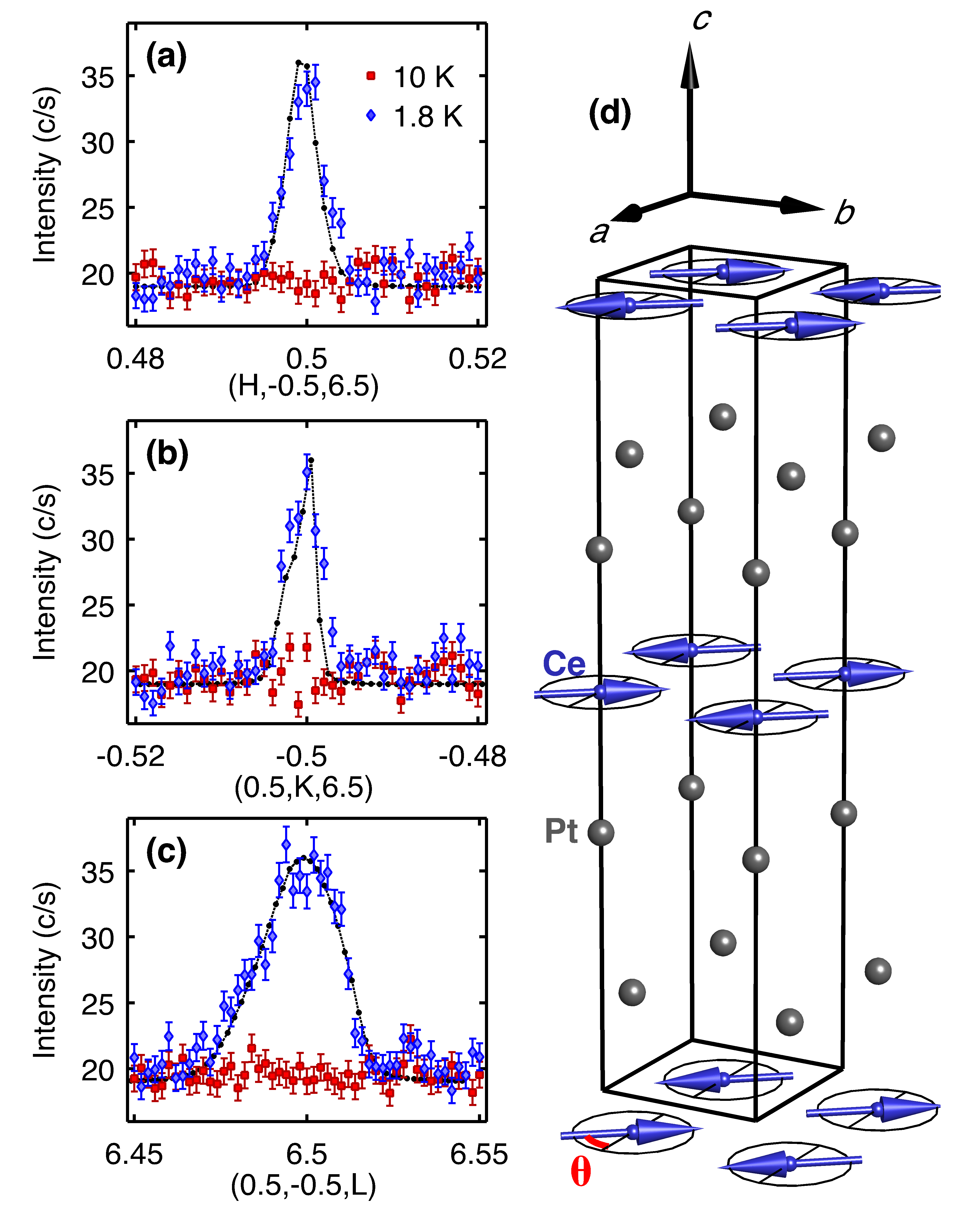
The magnetic order of CePt2In7 was successfully observed using MRXD, revealing unambiguously its commensurate propagation vector. Bragg peaks consistent with a propagation vector were observed at K. The magnetic origin of these Bragg peaks was verified by the resonance at the Ce- absorption edge as well as polarization analysis. -scans around the magnetic Bragg peak are presented in Figs. 1(a)-1(c) at K and can be compared with background scans done at 10 K. This magnetic Bragg peak has the same widths and shapes along , and as the structural Bragg peak . This indicates that the magnetic peak widths are limited by the crystal mosaicity and that a 3D long range magnetic order is achieved. Several other peaks consistent with were measured. It was observed that all experimentally accessible magnetic Bragg peaks have non-zero intensity, indicating the absence of any selection rules of the magnetic structure.
The fluorescence intensity of the sample was measured as function of the incident photon energy. It shows a maximum around keV corresponding to the Ce- absorption edge [Fig. 2(a)]. The intensity of the magnetic Bragg peak is strongly enhanced around this edge, indicating a resonant magnetic effect.Hill and McMorrow (1996) In contrast, the intensity of the structural Bragg peak shows a dip near this edge due to a larger absorption cross-section. The magnetic nature of the Bragg peak is further confirmed by the polarization analysis. The polarization is defined to be perpendicular to the scattering plane and the polarization is parallel to it.Hill and McMorrow (1996) In the electric dipole approximation of MRXD, charge scattering, related to the crystallographic structure, is allowed in the channel and is forbidden in the channel. Magnetic scattering has the opposite behaviour and appears in the channel and not in the one.Hill and McMorrow (1996) The Bragg peak is present in the channel and absent in the channel, clearly showing its magnetic nature [Fig. 2(b)]. This observation combined with the peak resonance at the Ce- edge establish unambiguously the magnetic origin of the Bragg peaks with the propagation vector .
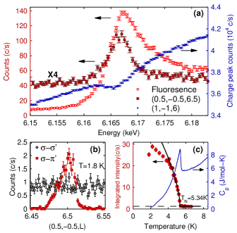
The temperature dependence of the magnetic Bragg peak has been measured from K up to 7 K in the channel. The width and position of this peak are temperature independent from K to . The integrated intensity indicates a Néel temperature of K, as determined by a power law fit above 4.4 K [Fig. 2(c)]. This transition temperature is in good agreement with the sharp peak observed in specific heat. The obtained critical exponent corresponds to a 3D Ising model with or a 3D XY model with .Collins (1989) Note that a beam injection occurred during the measurements at K and that the intensity above and below this temperature can not be compared accurately. However, a previous temperature dependence of the Bragg peak without the polarization analysis (not shown) does not have any feature at K.
The magnetic structure of the propagation vector was determined with the help of representation analysis performed with BasIreps.Rodríguez-Carvajal (1993) Only two irreducible representations with non-zero basis functions are possible at the Ce position in the space group I4/mmm. There is , a two-dimensional irreducible representation with basis vector , and , a one-dimensional irreducible representation with basis vector . Both representations do not have selection rules, in agreement with our observations, and hence can not be distinguished in this way.
We have determined that the structure must be described by with moments in the plane by performing azimuthal scans. These scans measure the intensity variation when the sample is rotated by azimuthal angle around the scattering vector . In MRXD, the scattering intensity is proportional to where is the magnetic structure factor and is the scattered photon wavevector.Hill and McMorrow (1996) Azimuthal rotations change the moment direction, modifying relative to a fixed . The scattered intensity is therefore expected to change with and this can be compared with that expected according to a magnetic structure model. The azimuth is defined relative to a reference Bragg peak, here chosen to be . The azimuthal angle is defined to be zero when the reference Bragg peak is in the scattering plane and forms the smallest angle with the incident photon wavevector .
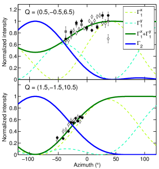
Multiple datasets of azimuthal scans were collected and are represented by different symbols in Fig. 3. These datasets were collected in similar conditions (with and without optimizing the different rotation and translation motors) and all show the same general tendency. For both irreducible representations, the magnetic structure is collinear and the azimuthal scans correlate directly to the moment orientation. The theoretical azimuthal dependence curves for moments pointing along the -axis (), the -axis () and the -axis () are shown in Fig. 3 for the magnetic Bragg peaks and . Experimental results are overlaid and show that the system can be described by the coexistence of and domains with equal population. Since the axes and are equivalent, one would indeed expect that both domains are present. In general, if a domain exists with a moment pointing in a direction within the plane, a domain with a moment pointing in a direction perpendicular to in the plane is expected with an equal population. It can be shown that the azimuthal dependence of for any in the plane is exactly the same one as the one of . Therefore, our results indicate the moments are in the plane but do not allow us to determine their exact orientation. The magnetic structure for antiferromagnetically ordered moments pointing in the basal plane at an angle from the -axis is schematized in Fig. 1(d).
From previous NQR experiments, it was claimed that at K an incommensurate magnetic order coexists with the commensurate order, and that the volume fraction of commensurate:incommensurate order was 0.25:0.75. In addition the maximal internal field due to the incommensurate order is determined to be slightly larger than the one from the commensurate order, suggesting a similar moment size for both orders. For these two reasons, the magnetic peak intensities originating from the incommensurate order can be expected to be similar to the ones of the commensurate order. However, no evidence for incommensurate magnetic peaks was found in our MRXD experiment from scans along the high symmetry directions in reciprocal space. Measurements were carried out at K for from to 8, from to 1.2, from to 1.2 and from to 1.5. This rules out likely incommensurate propagation vectors similar to those of other incommensurate magnetic phases in Ce-based heavy-fermion compounds,Fobes et al. (2017); Christianson et al. (2005); Yokoyama et al. (2006); Ohira-Kawamura et al. (2007, 2009); Raymond et al. (2014) but we can not exclude the presence of incommensurate modulations propagating elsewhere in reciprocal space.
III.2 Powder X-ray Diffraction Under Pressure
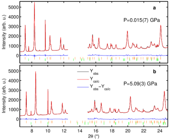
Powder X-ray diffraction patterns of CePt2In7 are shown in Fig. 4 at hydrostatic pressures GPa and GPa for a representative angular range. The general crystallographic structure, previously reported by Klimczuk et al.,Klimczuk et al. (2014) was confirmed by Rietveld refinement using FullProf.Rodríguez-Carvajal (1993) Two strong diffraction peaks from CePt2In7 appear in the angular range and this region has been excluded from the refinement to improve the sensitivity of the fit to weak features over the full angular range. Importantly, the diffraction peak profiles due to the CePt2In7 sample are significantly broader than the instrumental resolution and this can be attributed to strain. The presence of strain in polycrystalline sample of CePt2In7 was inferred previously in NQR measurements.Sakai et al. (2011) Our measurements remained in a hydrostatic regime up to the maximal applied pressure, as confirmed by the pressure independent widths of peaks due to scattering from quartz. However, the peak widths of CePt2In7 gradually broadened above GPa, which show a loss of the structural integrity in terms of either a larger strain or breaking of crystallites into smaller particles.
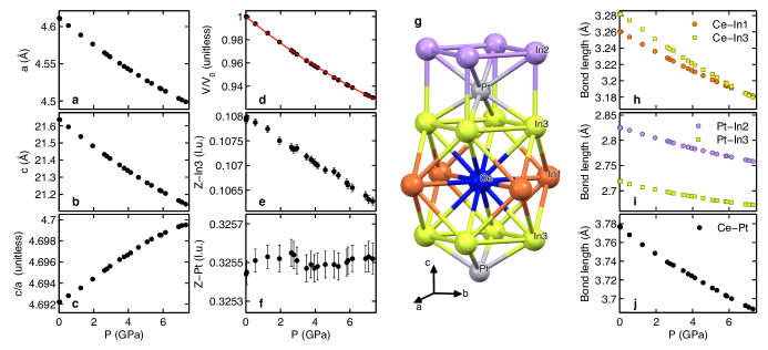
The refinement of the diffraction patterns was performed sequentially for increasing pressure and the results are presented in Fig. 5. We observe no obvious changes of the crystallographic structure related to the characteristic pressures GPa and GPa. The lattice constants and change monotonically up to the maximal applied pressure GPa [Figs. 5(a)-5(c)]. The Birch-Murnaghan equation of state was used to relate the crystal volume to the applied pressure :
| (1) |
where , and are respectively the initial bulk modulus and its derivative, and .Birch (1938) By fitting this equation to the data shown in Fig. 5(d), we obtain GPa and . Using the simple Murnaghan equation Murnaghan (1937) results in the same fitted values for and within errors. These values are similar to those reported for other members of the CenMmIn3n+2m family.Kumar et al. (2004) In these compounds, it was observed that adding MIn2 layers stiffens the structure and increases the bulk modulus: GPa for CeIn3, average GPa for Ce2MIn8 (2 layers CeIn3 + 1 layer MIn2) and average GPa for CeMIn5 (1 layer CeIn3 + 1 layer MIn2). The addition of a second MIn2 layer in CePt2In7 relative to CeMIn5 could then be expected to stiffen the lattice further. However, the bulk moduli appear very similar for CePt2In7 and the Ce-115s.
In CePt2In7, the Ce and Pt atoms sit at Wyckoff positions and , respectively, and the In atoms are distributed on three different positions (In(1) at , In(2) at and In(3) at ). The only adjustable fractional coordinates in the structure of CePt2In7 are the positions of the Pt and In(3) atoms. The fractional coordinate of In(3) changes monotonically with pressure [Fig. 5(e)] and the one of Pt is pressure independent [Fig. 5(f)]. This indicates a non-uniform compression along the -axis, with the strongest contraction occurring between the In(3)-planes and the Ce-In(1) planes [see Fig. 5(g)]. The pressure dependence of various bond lengths is presented in Figs. 5(h)-5(j) and they all decrease monotonically with increasing pressure. Interestingly, the Ce-In(3) bond is more significantly affected by pressure than the Ce-In(1) bond [Fig. 5(h)]. Since the Ce-In coupling is expected to be the strongest with the out-of-plane In(3) atoms,Haule et al. (2010); Shim et al. (2007) this change in distortion around the Ce atoms could modify significantly the ground-state Ce wavefunction.Willers et al. (2015)
IV Discussion
As mentioned previously, the pressure-temperature phase diagram of CeRhIn5 is very similar to the one of CePt2In7. Their magnetic structures at ambient pressure also share similarities: both have an antiferromagnetic order in the basal plane with moments lying in that plane.Fobes et al. (2017) However, the ordering in CeRhIn5 is incommensurate along the -axis in contrast with the commensurate ordering in CePt2In7. While CeCoIn5 and CeIrIn5 do not order magnetically at ambient pressure and zero magnetic field, it is possible to induce magnetic order with doping. In particular, substituting the Co or Ir sites with Rh leads to the coexistence of an incommensurate order with and a commensurate order with for a range of doping values.Christianson et al. (2005); Yokoyama et al. (2006); Ohira-Kawamura et al. (2007, 2009) It was shown for CeRh0.7Ir0.3In5 specifically that the moments lie in the basal plane for both the commensurate and incommensurate orders. Doping the In site with Cd in CeCoIn5 also stabilizes a commensurate order with .Nicklas et al. (2007) On the other hand, substituting Ce by Nd in CeCoIn5 leads to a propagation vector with ,Raymond et al. (2014) suggesting a spin-density wave in the basal plane with fundamentally different properties from the localized moment magnetism in CeRhIn5 and CePt2In7.
In these systems, superconductivity emerges in the vicinity of an AFM QCP, suggesting a magnetically-driven pairing mechanism of superconductivity. The knowledge of the magnetic structure is therefore a crucial element for identifying the magnetic fluctuations responsible for this electron-electron coupling. The AFM order in the basal plane prevails in these systems and CePt2In7 appears as a new example where magnetic fluctuations associated with this AFM order are the pairing glue of the pressure-induced superconductivity. It is important to note that the magnetic structure of CePt2In7 might change under pressure but it is unlikely to change the order in the basal plane. For example, the propagation vector in CeRhIn5 changes under pressure but the order in the basal plane is conserved.Majumdar et al. (2002); Llobet et al. (2004); Raymond et al. (2008); Aso et al. (2009)
Based on NQR experiments, it was suggested that in single crystals of CePt2In7 there is a coexistence of commensurate and incommensurate orders at ambient pressure.Sakai et al. (2014, 2011) Specifically, sharp peaks in the spectrum can be attributed to a basal plane AFM order with moments pointing along the -axis or the -axis. This was interpreted as a commensurate order. On the other hand, broad features are also observed in the spectrum and were attributed to a distribution of internal fields at the In(2) and In(3) sites. This was interpreted as an incommensurate order similar to the one of CeRhIn5.Curro (2006)
Our results presented in section III.1 confirm the presence of a commensurate order but do not reveal the presence of an incommensurate order along the high symmetry directions in reciprocal space indicated in section III.1. The scenario involving the coexistence of both commensurate and incommensurate orders remains a possibility: we cannot rule out incommensurate modulations propagating elsewhere in reciprocal space, and the volume fraction and/or moment size could be too small to be detected under our current experimental conditions.
On the other hand, we propose an alternative interpretation of the broad features observed in the NQR experiments that do not require the presence of an additional incommensurate order. With no restriction on the precise moment direction in the basal plane provided by our MXRD experiments, the distribution of internal fields observed by NQR could be generated if either the moment directions in the plane fluctuate, or there exist multiple domains with different moment orientations (different values of in Fig. 1). This commensurate-only scenario for the magnetic order in CePt2In7 requires a coexistence of domain-types; those with arbitrary moment orientations in the plane as outlined above, and those where the moments are rigidly aligned with the - and -axes. Here crystal strain could play an important role in stabilizing one type of domain over the other.
In NQR experiments, different results for the reported spectra are obtained from polycrystalline and single crystal samples of CePt2In7.Sakai et al. (2011); apRoberts Warren et al. (2010) These discrepancies are readily attributable to crystal/surface strain effects that vary in propensity with the sample crystallite size. Indeed, this is supported by the broad structural peaks in our high-resolution powder X-ray diffraction experiment on CePt2In7. In the NQR studies only sharp features are observed for powder samples, in contrast with the presence of broad features for single crystals. Furthermore, applied pressure on single crystals suppresses the contribution of the broad features.Sakai et al. (2011) Taken together, these two effects indicate that strain, either from surface strain from the grains in polycrystalline samples or stimulated by pressure, promotes the ordering with moments aligned along the -axis or the -axis. At the same time, in the absence of strain, the moments may align along an arbitrary direction in the plane. In this scenario, enhanced strain thus leads to an effective in-plane anisotropy that favors the alignment of the moments along the -axis or -axis.
It is interesting then to note that the superconductivity is stabilized in a wider pressure range in powder samples and that it only appears in single crystals when the NQR signature interpreted in terms of incommensurate order is completely suppressed.Sakai et al. (2011); Sidorov et al. (2013) This suggests that domains with moments not aligned along the -axis or the -axis are detrimental to the formation of superconductivity in CePt2In7.
Finally, we note that even if the magnetic structure presented in section III.1 is the simplest solution to explain the results, it is not the only possible one. Since the lattice of CePt2In7 is body-centered, the propagation vector is not equivalent to . This can lead either to two different -domains, which was assumed in section III.1, or a multi- structure, as observed for example in the heavy fermion CeRh2Si2, which also has a body-centered tetragonal lattice.Kawarazaki et al. (2000) A complete description of the multi- structure in CePt2In7 is given in the appendix. In such a multi- structure, the moments between the nearest neighbouring Ce layers can be non-collinear while all the moments are collinear in a single- structure. This non-collinearity suggests an effective decoupling of the nearest neighbour layers while keeping a coupling to the next-nearest neighbour planes, consequently forming two decoupled yet inter-penetrating sublattices. This scenario is plausible for the body-centered tetragonal lattice because of the presence of competing interactions. It was even suggested theoretically that the frustration in body-centered tetragonal lattices can destabilize long-range magnetic order and lead to spin liquid states in heavy fermion compounds.Farias et al. (2016) The aforementioned discussion about the moment directions in the single- model, and its application for consistently explaining previously reported NQR spectra, can also be done using the multi- structure. Our results do not allow us to establish unambiguously if the single- structure or the multi- structure is the correct one. In fact, these two scenarios cannot be distinguished in a simple scattering experiment; doing so would require the application of either uniaxial strain or magnetic fields to control the magnetic domain formation in a single crystal sample.
V Summary
We have shown that the crystallographic structure of CePt2In7 changes monotonically with pressure up to GPa at room temperature. We also investigated the magnetic order of CePt2In7 at ambient pressure below K by magnetic resonant X-ray diffraction. This order is characterized by a commensurate propagation vector . The magnetic origin of these diffraction peaks was confirmed by their resonance at the Ce- absorption edge and by polarization analysis. Azimuthal scans confirm that the moments lie in the basal plane. The magnetic structure can be described by a single- structure or by a multi- structure. Both structures cannot be distinguished in a simple scattering experiment as reported here and the single- structure is discussed for simplicity. The presence of incommensurate order in CePt2In7 was previously reported based on NQR experiments. Our measurements could not reveal the presence of such an order but are insufficient to exclude it completely. Using our results we propose a new scenario for the ambient pressure ground state of CePt2In7 that is described only by commensurate magnetic order; namely a coexistence of domains wherein the moments are either rigidly aligned along the - and -axes, or arbitrarily aligned within the plane. Crystal strain is argued to be an effective tuning parameter for controlling the relative volume fractions of the two types of domain, thus providing a means for a consistent description of both the scattering data reported here, and previously reported NQR spectra obtained on both polycrystalline and single crystal samples.
Acknowledgements
The authors are thankful to M. Kenzelmann, D. G. Mazzone and F. Ronning for fruitful discussions. This research received support from the Natural Sciences and Engineering Research Council of Canada (Canada). Work at Los Alamos National Laboratory was performed under the auspices of the US Department of Energy, Office of Basic Energy Sciences, Division of Materials Sciences and Engineering. XMaS is a UK mid-range facility supported by EPSRC.
Note added. - During the preparation of this manuscript, we became aware of another report where the magnetic structure of CePt2In7 was investigated using neutron diffraction.Raba et al. (2017) In agreement with our results, they report a commensurate propagation vector and moments lying in the basal plane. The reported structure corresponds to a multi- structure with non-collinear moments.
*
Appendix A Single- and multi- structures
A.1 Single- structure
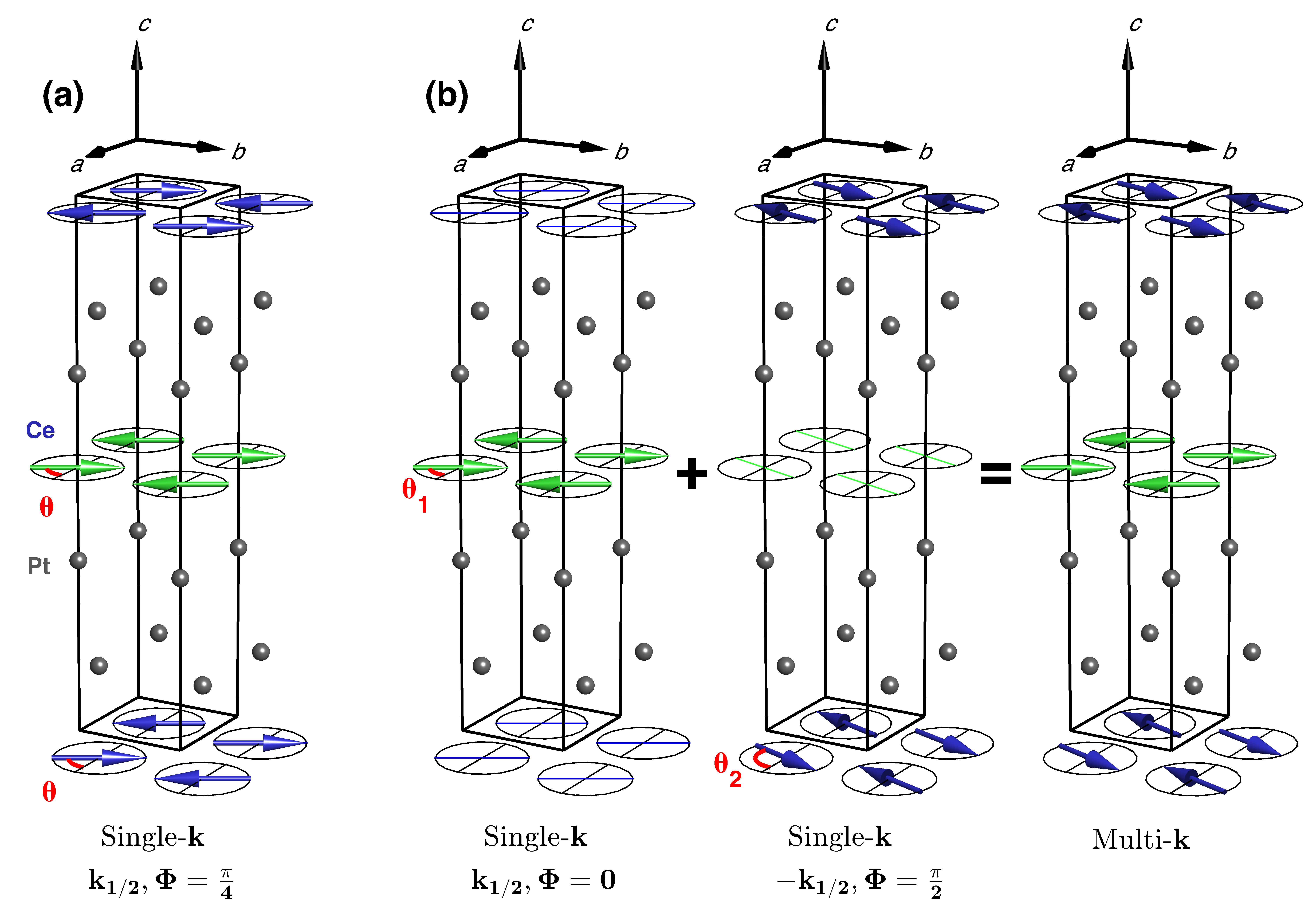
The simplest magnetic structure model for CePt2In7 is described by the single propagation vector . This is represented in Fig. 6(a). In the unit cell, there are two Ce ions which are related by the body-centering symmetry. They are distinguished by the blue and green colors in Fig. 6. For a general single-k structure, the moments and at the blue and green sites, respectively, are expressed as:
| (2) |
| (3) |
Here the parameter is the angle of the moment in the plane, which can take any value. To reproduce the data, the presence of two equally populated domains with and is assumed. The parameter is a global phase that cannot be measured with scattering techniques. For physical reasons, we chose to generate equal moments for and . The single- structure is therefore defined by:
| (4) |
| (5) |
A.2 Multi- structure
Due to the body-centering symmetry, and are not equivalent and therefore, a magnetic structure can form that is composed of two propagation vectors. In a general way, the moments are defined at the blue and green sites, respectively, by:
| (6) |
| (7) |
where and are related to the propagation , and and are related to . It is again assumed that there are two equally populated domains with and . Experimentally, this gives exactly the same scattering as the single- structure. We must choose and to have equal moments on the blue and green sites for any and . An elegant choice is and where is an integer. It evidences the decoupling of the nearest-neighbour layers. For , we obtain:
| (8) |
and
| (9) |
The structure is therefore defined by three parameters: the moment size , the angle of the first propagation vector and the angle of the second propagation vector. While is expected to be constant, and can take any value. Note that the single- structure is obtained if .
References
- D. Thompson and Fisk (2012) J. D. Thompson and Z. Fisk, Journal of the Physical Society of Japan 81, 011002 (2012).
- Gegenwart et al. (2008) P. Gegenwart, Q. Si, and F. Steglich, Nature Physics 4, 186 (2008).
- Willers et al. (2015) T. Willers, F. Strigari, Z. Hu, V. Sessi, N. B. Brookes, E. D. Bauer, J. L. Sarrao, J. D. Thompson, A. Tanaka, S. Wirth, L. H. Tjeng, and A. Severing, Proceedings of the National Academy of Sciences 112, 2384 (2015).
- Haule et al. (2010) K. Haule, C.-H. Yee, and K. Kim, Physical Review B 81, 195107 (2010).
- Klimczuk et al. (2014) T. Klimczuk, O. Walter, L. Müchler, J. W. Krizan, F. Kinnart, and R. J. Cava, Journal of Physics: Condensed Matter 26, 402201 (2014).
- Sakai et al. (2014) H. Sakai, Y. Tokunaga, S. Kambe, F. Ronning, E. D. Bauer, and J. D. Thompson, Physical Review Letters 112, 206401 (2014).
- Bauer et al. (2010a) E. D. Bauer, H. O. Lee, V. A. Sidorov, N. Kurita, K. Gofryk, J.-X. Zhu, F. Ronning, R. Movshovich, J. D. Thompson, and T. Park, Physical Review B 81, 180507 (2010a).
- Park et al. (2006) T. Park, F. Ronning, H. Q. Yuan, M. B. Salamon, R. Movshovich, J. L. Sarrao, and J. D. Thompson, Nature 440, 65 (2006).
- Altarawneh et al. (2011) M. M. Altarawneh, N. Harrison, R. D. McDonald, F. F. Balakirev, C. H. Mielke, P. H. Tobash, J.-X. Zhu, J. D. Thompson, F. Ronning, and E. D. Bauer, Physical Review B 83, 081103 (2011).
- Krupko et al. (2016) Y. Krupko, A. Demuer, S. Ota, Y. Hirose, R. Settai, and I. Sheikin, Physical Review B 93, 085121 (2016), arXiv:1602.06768 .
- Chen et al. (2016) R. Y. Chen, S. J. Zhang, E. D. Bauer, J. D. Thompson, and N. L. Wang, Physical Review B 94, 035161 (2016).
- Park et al. (2011) T. Park, V. A. Sidorov, H. Lee, F. Ronning, E. D. Bauer, J. L. Sarrao, and J. D. Thompson, Journal of Physics: Condensed Matter 23, 094218 (2011).
- Pixley et al. (2015) J. H. Pixley, L. Deng, K. Ingersent, and Q. Si, Physical Review B 91, 201109 (2015).
- apRoberts Warren et al. (2010) N. apRoberts Warren, A. P. Dioguardi, A. C. Shockley, C. H. Lin, J. Crocker, P. Klavins, and N. J. Curro, Physical Review B 81, 180403 (2010).
- Sakai et al. (2011) H. Sakai, Y. Tokunaga, S. Kambe, H.-O. Lee, V. A. Sidorov, P. H. Tobash, F. Ronning, E. D. Bauer, and J. D. Thompson, Physical Review B 83, 140408 (2011).
- Månsson et al. (2014) M. Månsson, K. Prša, Y. Sassa, P. H. Tobash, E. D. Bauer, C. Rusu, D. Andreica, O. Tjernberg, K. Sedlak, M. Grioni, T. Durakiewicz, and J. Sugiyama, Journal of Physics: Conference Series 551, 012028 (2014).
- Sidorov et al. (2013) V. A. Sidorov, X. Lu, T. Park, H. Lee, P. H. Tobash, R. E. Baumbach, F. Ronning, E. D. Bauer, and J. D. Thompson, Physical Review B 88, 020503 (2013).
- Tobash et al. (2012) P. H. Tobash, F. Ronning, J. D. Thompson, B. L. Scott, P. J. W. Moll, B. Batlogg, and E. D. Bauer, Journal of Physics: Condensed Matter 24, 015601 (2012).
- Bauer et al. (2010b) E. D. Bauer, V. A. Sidorov, H. Lee, N. Kurita, F. Ronning, R. Movshovich, and J. D. Thompson, Journal of Physics: Conference Series 200, 012011 (2010b).
- Willmott et al. (2013) P. R. Willmott, D. Meister, S. J. Leake, M. Lange, A. Bergamaschi, M. Böge, M. Calvi, C. Cancellieri, N. Casati, A. Cervellino, Q. Chen, C. David, U. Flechsig, F. Gozzo, B. Henrich, S. Jäggi-Spielmann, B. Jakob, I. Kalichava, P. Karvinen, J. Krempasky, A. Lüdeke, R. Lüscher, S. Maag, C. Quitmann, M. L. Reinle-Schmitt, T. Schmidt, B. Schmitt, A. Streun, I. Vartiainen, M. Vitins, X. Wang, and R. Wullschleger, Journal of Synchrotron Radiation 20, 667 (2013).
- Angel et al. (1997) R. J. Angel, D. R. Allan, R. Miletich, and L. W. Finger, Journal of Applied Crystallography 30, 461 (1997).
- Prescher and Prakapenka (2015) C. Prescher and V. B. Prakapenka, High Pressure Research 35, 223 (2015).
- Rodríguez-Carvajal (1993) J. Rodríguez-Carvajal, Physica B: Condensed Matter 192, 55 (1993).
- Hill and McMorrow (1996) J. P. Hill and D. F. McMorrow, Acta Crystallographica A 52, 236 (1996).
- Collins (1989) M. F. Collins, Magnetic critical scattering (Oxford University Press, 1989).
- Fobes et al. (2017) D. M. Fobes, E. D. Bauer, J. D. Thompson, A. Sazonov, V. Hutanu, S. Zhang, F. Ronning, and M. Janoschek, Journal of Physics: Condensed Matter 29, 17LT01 (2017).
- Christianson et al. (2005) A. D. Christianson, A. Llobet, W. Bao, J. S. Gardner, I. P. Swainson, J. W. Lynn, J.-M. Mignot, K. Prokes, P. G. Pagliuso, N. O. Moreno, J. L. Sarrao, J. D. Thompson, and A. H. Lacerda, Physical Review Letters 95, 217002 (2005).
- Yokoyama et al. (2006) M. Yokoyama, H. Amitsuka, K. Matsuda, A. Gawase, N. Oyama, I. Kawasaki, K. Tenya, and H. Yoshizawa, Journal of the Physical Society of Japan 75, 103703 (2006).
- Ohira-Kawamura et al. (2007) S. Ohira-Kawamura, H. Shishido, A. Yoshida, R. Okazaki, H. Kawano-Furukawa, T. Shibauchi, H. Harima, and Y. Matsuda, Physical Review B 76, 132507 (2007).
- Ohira-Kawamura et al. (2009) S. Ohira-Kawamura, H. Kawano-Furukawa, H. Shishido, R. Okazaki, T. Shibauchi, H. Harima, and Y. Matsuda, Phys. Status Solidi A 206, 1076 (2009).
- Raymond et al. (2014) S. Raymond, S. M. Ramos, D. Aoki, G. Knebel, V. P. Mineev, and G. Lapertot, Journal of the Physical Society of Japan 83, 013707 (2014).
- Birch (1938) F. Birch, Journal of Applied Physics 9, 279 (1938).
- Murnaghan (1937) F. D. Murnaghan, American Journal of Mathematics 59, 235 (1937).
- Kumar et al. (2004) R. S. Kumar, A. L. Cornelius, and J. L. Sarrao, Physical Review B 70, 214526 (2004).
- Shim et al. (2007) J. H. Shim, K. Haule, and G. Kotliar, Science 318, 1615 (2007).
- Nicklas et al. (2007) M. Nicklas, O. Stockert, T. Park, K. Habicht, K. Kiefer, L. D. Pham, J. D. Thompson, Z. Fisk, and F. Steglich, Physical Review B 76, 052401 (2007).
- Majumdar et al. (2002) S. Majumdar, G. Balakrishnan, M. R. Lees, D. M. Paul, and G. J. McIntyre, Physical Review B 66, 212502 (2002).
- Llobet et al. (2004) A. Llobet, J. S. Gardner, E. G. Moshopoulou, J.-M. Mignot, M. Nicklas, W. Bao, N. O. Moreno, P. G. Pagliuso, I. N. Goncharenko, J. L. Sarrao, and J. D. Thompson, Physical Review B 69, 024403 (2004).
- Raymond et al. (2008) S. Raymond, G. Knebel, D. Aoki, and J. Flouquet, Physical Review B 77, 172502 (2008).
- Aso et al. (2009) N. Aso, K. Ishii, H. Yoshizawa, T. Fujiwara, Y. Uwatoko, G.-F. Chen, N. K. Sato, and K. Miyake, Journal of the Physical Society of Japan 78, 073703 (2009).
- Curro (2006) N. J. Curro, New Journal of Physics 8, 173 (2006).
- Kawarazaki et al. (2000) S. Kawarazaki, M. Sato, Y. Miyako, N. Chigusa, K. Watanabe, N. Metoki, Y. Koike, and M. Nishi, Physical Review B 61, 4167 (2000).
- Farias et al. (2016) C. Farias, C. Thomas, C. Pépin, A. Ferraz, C. Lacroix, and S. Burdin, Physical Review B 94, 134420 (2016).
- Raba et al. (2017) M. Raba, E. Ressouche, N. Qureshi, C. V. Colin, V. Nassif, S. Ota, Y. Hirose, R. Settai, P. Rodière, and I. Sheikin, Physical Review B 95, 161102 (2017).