acmlicensed
\isbn978-1-4503-4981-9/17/10\acmPrice$15.00
\teaser
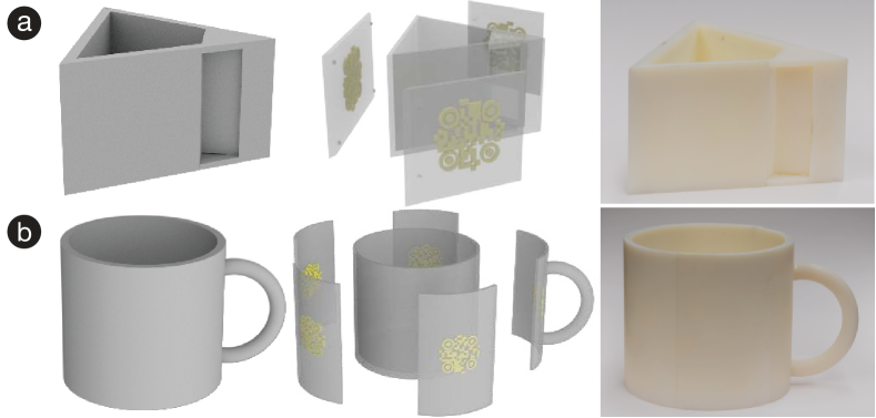
![[Uncaptioned image]](/html/1707.05754/assets/x1.png) (a) AirCode tagging tool takes as inputs a mesh, a user-specified region, and embedded data.
(b) It first determines the air pocket parameters, including the depth and thickness , for a fabrication material.
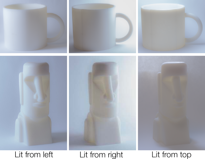
(c) An AirCode tag is embedded inside the object, without changing its geometry or appearance.
(d) The fabricated tag is invisible under environmental lighting.
(e) Using our imaging system that separates out the
global scattering effects,
the user detects the embedded tag and retrieve the data.
“Moai” by gravityisweak /
CC BY 3.0 / modified from original.
(a) AirCode tagging tool takes as inputs a mesh, a user-specified region, and embedded data.
(b) It first determines the air pocket parameters, including the depth and thickness , for a fabrication material.
(c) An AirCode tag is embedded inside the object, without changing its geometry or appearance.
(d) The fabricated tag is invisible under environmental lighting.
(e) Using our imaging system that separates out the
global scattering effects,
the user detects the embedded tag and retrieve the data.
“Moai” by gravityisweak /
CC BY 3.0 / modified from original.
AirCode: Unobtrusive Physical Tags for Digital Fabrication
Abstract
We present AirCode, a technique that allows the user to tag physically fabricated objects with given information. An AirCode tag consists of a group of carefully designed air pockets placed beneath the object surface. These air pockets are easily produced during the fabrication process of the object, without any additional material or postprocessing. Meanwhile, the air pockets affect only the scattering light transport under the surface, and thus are hard to notice to our naked eyes. But, by using a computational imaging method, the tags become detectable. We present a tool that automates the design of air pockets for the user to encode information. AirCode system also allows the user to retrieve the information from captured images via a robust decoding algorithm. We demonstrate our tagging technique with applications for metadata embedding, robotic grasping, as well as conveying object affordances.
doi:
https://doi.org/10.1145/3126594.3126635keywords:
digital fabrication; 3D printing; unobtrusive tags; air pockets; sensingcategory:
I.2.10 Vision and Scene Understanding Modeling and recovery of physical attributescategory:
J.6 Computer-Aided Engineering Computer-aided design (CAD)category:
H.5.m. Information Interfaces and Presentation (e.g. HCI) Miscellaneous1 Introduction
Whether we board airplanes, borrow books from a library, or line up to check out at grocery stores, one common minutia we benefit from is the optical tag, a machine-readable, black-and-white pattern printed on a surface to contain information about the item on which it is printed. Today, optical tags have become a technological staple of everyday life, establishing “hyperlinks” between physical surfaces and digital information.
In this paper, we extend the idea of hyperlinks and propose AirCode, an unobtrusive tagging system for 3D printed objects. 3D printing has the unprecedented ability to create customized, one-off parts, necessitating tags that carry individualized information. For instance, when fabricating many similarly shaped components that are assembled together, it would be beneficial to tag each component to facilitate correct assembly. Physical tags also establish a link between physically manufactured objects and digital computing systems: a robot can better recognize a 3D printed object and its poses for manipulation, by reading tags attached to the object.
In developing a practical tagging system for 3D printing, several desiderata are of importance. (i) Tags need to be embedded during the 3D printing process, not as a separate post-processing step. This is because post-processing not only introduces extra cost but requires one to distinguish individual objects in the first place—a step that by itself benefits from tags. (ii) Tags need to be printable with existing 3D printers. Ideally, even a single-material printer should be able to tag its fabrication. (iii) Tags need to be unobtrusive with respect to the shapes and appearance of 3D printed objects.
To our knowledge, none of the existing solutions satisfies these requirements. For example, traditional optical tags fail with respect to (i) and (iii), and Radio Frequency Identification (RFID) tags break (i) and (ii).
AirCode satisfies all above requirements. Our key idea is simply placing thin air pockets under the surface of 3D printed objects. Without requiring any additional material or post processing, air pockets can be easily produced by most 3D printers. Meanwhile, air, drastically different from 3D printing materials in terms of optical properties, changes how light is scattered after penetrating the material surface.
Most plastic 3D printing materials, even those considered opaque, scatter light, while the amount of light penetrating and scattered is often weak; most of the light is directly reflected at the surface. Consequently, the effects of air pockets on object appearance can be made imperceptible to our naked eyes. But the user can separate out the subsurface scattered light through a computational imaging method that requires only a conventional camera and projector, and in turn amplify the light transport effects of air pockets. We demonstrate that by carefully designing the subsurface air pockets, one can conceal information in imperceptible yet machine-readable tags.
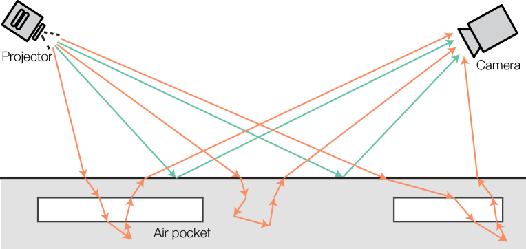
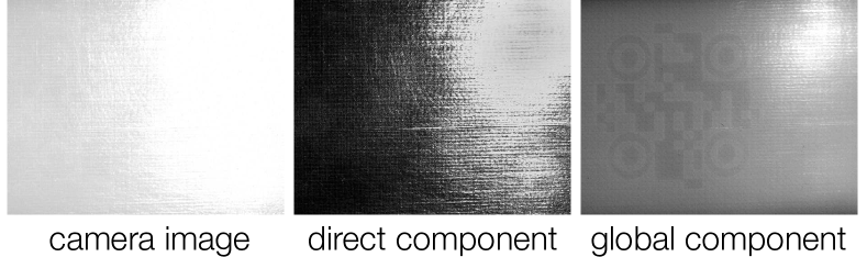
We present a design tool that determines the shapes and positions of subsurface air pockets to encode user-specified information. Our system also enables the user to separate the global illumination light transport from the direct illumination, using computational imaging [30]. The direct component accounts for light rays reflected by the object surface and thus is unaffected by subsurface air pockets. The global component is dominated by light rays that are scattered after penetrating the surface (Figure 1). It is affected by the air pockets and thus conveys the embedded information. Meanwhile, it is unaffected by direct illumination effects such as specular highlights which often frustrate machine vision systems. As a result, our method of reading subsurface tags is robust to variation in object pose and camera angle.
2 Related Work
The emergence of rapid fabrication tools allows users to prototype personal objects for fabrication [14]. Recently, HCI researchers have created various design tools to facilitate the design process [5, 28, 38, 39]. For example, On-the-fly Printing enables incremental printing during the modeling stage [33]; ChronoFab, a 3D modeling tool, allows creating motion sculptures [22]. The size of a personal fabricated object can range from hair fibers [24], palm-size pieces [29, 20], to room-size objects [2]. To facilitate interaction with these customized objects, unobtrusive physical tags are desired to link physical objects with digital systems.
In order to apply a tag to a physical object, perhaps among the first choices is the conventional optical barcode, such as a 1D linear barcode and a 2D QR code. Optical barcodes have been used in applications ranging from augmented reality marking, robot-human interaction, to context-aware gesture interaction [12, 43, 6]. Despite their straightforward use on digital displays or printed materials, they suffer from some limitations. First, barcodes are obtrusive, sometimes even distracting, since they always occupy a surface region and are visible to our naked eyes. Second, the decoding process often requires a relatively clean and sharp image. But when we embed the barcode beneath a surface, the imaging results become blurry, noisy, and of low contrast (Figure 7). Our AirCode system is inspired by existing barcodes but tailored to enable robust decoding.
RFID is also commonly used for tagging but typically requires a postprocessing step to install RFID circuits inside an object [36]. In contrast, our proposed method requires no postprocessing. This is desirable if one needs a fully automatic pipeline wherein a robotic system can manipulate the object immediately after its manufacturing. Recent work on 3D printing of electronics [11] is promising for making objects with embedded RFIDs. But this technology is not yet accessible to most users, and the fabrication is also more costly in comparison to our method relying on only commodity 3D printers. Essentially an optical code, AirCode complements RFID tags. For example, it is easy to estimate object orientation using optical codes while not straightforward for RFIDs.
Another approach is printing with invisible inks that can be revealed under ultraviolet light [19]. An additional process (after the fabrication) is needed to color the object with UV-visible inks. Moreover, UV ink can fade under direct exposure to lighting or wear off after prolonged surface interaction with users and other objects, whereas air pockets used in AirCode tags are well shielded under the object surface.
Recent work has explored other tagging mechanisms such as encoding in the time sequence of audio signals or the acoustic frequency spectrum [17, 23, 25, 34]. For instance, Acoustic Barcodes [17] encode binary IDs in structured patterns of physical notches on an object surface, and the IDs are machine readable via analyzing the sound produced by swiping the notches. This type of methods requires changing the shape of the object when applying tags. In addition, physical contacts are required to read the tags, whereas we are able to detect an AirCode tag through a camera system, without touching or knowing the exact location of the object.
Sharing a similar goal to our approach, Willis et al. \shortciteWillisW13 used Terahertz (THz) imaging devices to scan internal structures of 3D printed objects. While demonstrating promising results, these methods require expensive imaging equipment and are limited by a relatively low spatial imaging resolution (e.g., 3030 as reported in [41]). In contrast, AirCode tags can be captured by a conventional, low-cost camera system and produce high-resolution images of the tags.
With the emergence of advanced 3D printers, subsurface scattering has been recently exploited for appearance fabrication [18, 32]. As a pioneer work in realistic rendering, Jensen et al. [21] modeled subsurface scattering using dipole approximation to the bidirectional scattering surface reflectance distribution functions (BSSRDF). Based on these approximations, to fabricate a desired translucent appearance, Has̆an et al. \shortciteHasanFMPR10 composite layered materials to obtain user-specified BSSRDFs in 3D printed objects, In comparison, our work is not meant to physically reproduce specific material appearance. Instead, we aim to preserve the appearance of objects while embedding information in them.
3 Method Overview
Our framework powering AirCode exploits subsurface light scattering to design tags that are imperceptible but machine-readable. Our system consists of three major steps.
Preprocessing: Determining Air Pocket Parameters
Provided a fabrication material, our system first determines the geometric parameters of air pockets—the parameters that describe the size and depth of subsurface air pockets (Figure AirCode: Unobtrusive Physical Tags for Digital Fabrication-b) such that the air pockets are invisible to the human eye, and meanwhile produce sufficiently clear features on the global-component image for reliable tag reading. To determine these parameters, we measure the material’s subsurface scattering properties and in turn analyze the influence of air pockets on the material’s surface appearance. This step is a one-time process for a given fabrication material.
AirCode Design
When the user specifies a piece of information (represented as a bit string) and a 3D model for fabrication, our system generates a layout of air pockets placed beneath the surface of the 3D model without changing its surface shape. Each air pocket in this layout is constructed with the parameters estimated in the preprocessing step. The air pocket layout serves two purposes: (i) it enables the reading algorithm to robustly locate AirCode tags on a global-component image, and (ii) it embeds the given information. The output of this step is a 3D model with air pockets embedded, ready for physical fabrication.
AirCode Reading
Our method to read AirCode tags that are embedded in a physical object is based on a computational imaging technique [30]. The imaging method produces a direct and a global component image, of which the latter conveys the influence of the subsurface air pockets. Because of subsurface scattering, the global component image is blurry and of low contrast. And 3D printing artifacts (such as the printhead motion patterns) further introduce image noise. Our system locates the tags on the global-component image using a multi-scale elliptical detector and then retrieve embedded information using an SVM classifier trained on the fly.
4 Example Applications
AirCode provides an unobtrusive way of embedding user-specified information in physical objects, and the tag is produced in the process of fabrication, without any postprocessing. Not only is AirCode directly applicable in rapid prototyping (such as 3D printing) but also in many mass-produced products. Here we describe a few applications enabled by AirCode tags. We also refer to the supplemental video for the demonstration.
4.1 Embedding Metadata in Physical Objects
Many digital productions carry metadata, a piece of information that is not directly perceptible but can be retrieved to provide additional resources and digital identification [16]. Perhaps the most well-known are the metadata embedded in photographs, providing information such as capture date, exposure time, focal length, GPS location, and copyright.
AirCode provides a means of embedding similar metadata but for physical objects. It can serve as a metadata holder to provide additional information, resources, copyright, and digital identification for 3D printed objects. For example, after designing an artistic statue, the artist can embed a link to a webpage about the background of this statue or the artist’s personal website or copyright claim in the statue before fabricating it. Later, when the client receives the statue, by retrieving the embedded AirCode tags, the client can learn more information and resources about the statue and the artist.
We demonstrate the use of AirCode with a Moai statue, as shown in Figure AirCode: Unobtrusive Physical Tags for Digital Fabrication. The user specifies a region to embed in the input model a link to the statue’s webpage. The statue with this AirCode tag is then 3D printed. Since the tags are embedded beneath the surface of the statue, they do not alter the geometry or the appearance of the statue. However, by using our global-component imaging system, the embedded tag can be detected and the webpage is retrieved.
4.2 Robotic Grasping
AirCode tags also help robotic manipulators interact with man-made objects. In robotic grasping tasks, a challenging problem is to recognize an object, estimate its pose, and decide where to grasp. Most robotic systems rely on the image camera and/or depth sensor to infer the shape and pose of an object and plan grasping motion. However, if a crucial region of an object (e.g., the handle of a mug) is occluded from the sensor, it is very hard, if not impossible, for the robot to identify grasping points that are in the occluded region.
If an object embeds AirCode tags, the camera system of a robotic manipulator can recognize the object and retrieve its complete 3D model by reading the tags. More remarkably, as we will present in the AirCode Design and Reading section, locating the AirCode tags further allows the system to estimate the object pose (i.e., position and orientation) with respect to the camera. Knowing the 3D model and the pose of an object, the robot has complete information to plan the grasping. We also note that since AirCode tags are generated in the process of object fabrication, the robotic system can identify and manipulate the object immediately after its fabrication, without any post processing to add optical barcodes or RFIDs. This is highly desirable for automated production pipelines (such as those for automated assembly).
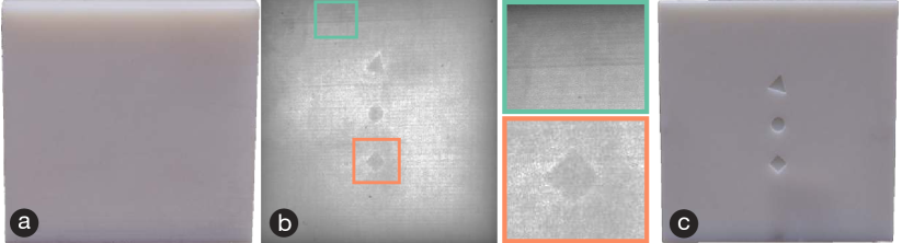
We demonstrate with two objects (see Figure 2). In the triangular drawer (Figure 2-a), we embed three different AirCode tags on each side of the drawer. In the mug (Figure 2-b), we embed six tags under the curved surface of the mug. The tags are made unique from each other. As long as one of the tags is captured and read by the imaging system, the robotic manipulator can identify the object and estimate its pose.
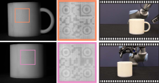
AirCode tags enable the robotic manipulator to sidestep the vision-based recognition problem and directly identify the object. Consequently, the robot manipulator can grasp a handle that is completely occluded from the camera (see Figure 3 and supplemental video). This is a particularly challenging case for vision-based grasping methods because from a directly captured image, it is hard to infer the parts that are occluded from the camera.
4.3 Conveying Object Affordance
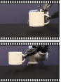
Object affordance is “the particular ways in which an actor, or set of actors, perceives and uses an object” [15, 27]. For example, the handles on a teapot offer an obvious affordance for holding. Some objects can be interpreted to afford different uses, while many customized objects may not have an easily interpretable affordance. For example, Figure 4 shows three objects from Thingiverse, a 3D model sharing website. These models are designed with various intended functional purposes while offering unique aesthetics. However, the artistically designed shapes can conceal their affordances—for instance, the cat model (Figure 4-a) has a carefully designed distribution of mass in order to hold an iPhone stably, but this intended use can be unintuitive for the user to interpret.
AirCode tags enable an unobtrusive way to embed information about an object’s affordances in the object itself during the design process. For example, the designer can embed a link to a webpage that illustrates the object’s use without sacrificing the appearance or the artistically designed shape of the object. Then the user can extract the link and understand its affordance. Furthermore, the embedded tags also allow a robotic system to know how to precisely manipulate an object. As customized 3D models become available online, we envision that AirCode tags can help communicate their origins and uses more seamlessly.
4.4 Extension: Paper Watermarking
The idea of using air pockets to alter the global component of an image and thereby embed information can be extended beyond 3D printed objects or plastic materials. In general, as long as the materials are not fully opaque, it is possible to exploit subsurface light transport for tagging. As a demonstration of extending AirCode tags to other materials, here we embed watermarks in a paper by stacking a few thinner papers together. We carve a pattern on one paper and sandwich it in other papers, and then stick all thin papers together.
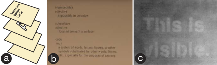
Particularly, the paper watermark consists of four layers of thinner papers. The top layer is printed with regular visible text or data. The second layer is carved with a stencil to hold a hidden message. The last two layers are blank papers. As shown in Figure 5 and the video, the hidden message is invisible under normal lighting conditions but can be detected using our imaging method. In this case, the surface texture (i.e., the printed text) will also affect the global component image. We exploit the direct component image which includes only the surface texture to create a mask for the printed text. With this mask, we can remove the printed text in the global component image using a PatchMatch-based inpainting algorithm (e.g., featured in Adobe Photoshop). We envision that in the future this technique can be used as unobtrusive codes or anti-forgery tags on product packages and books.
5 AirCode Design and Reading
We now present the core algorithmic components of our system, the AirCode generation and reading. The basic element of an AirCode tag is an air pocket placed beneath the object surface. We will present an analysis to estimate the geometric parameters of air pockets in Determining Air Pocket Parameters. In this section, we focus on the layout of air pockets: we first present a method to generate a subsurface air pocket structure that encodes user-provided information; we then describe our method that retrieves the embedded information from the global-component image of an object:
Our AirCode generation algorithm works in tandem with the imaging method that separates the global illumination of light transport from the directional illumination. We will describe the imaging details in the next section, but note here the challenges arising from the global-component imaging, to rationalize algorithmic choices in our tag design:
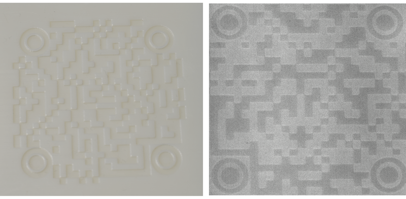
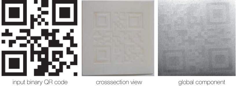
Figure 6 shows the cross section of a 3D printed model with three air pockets placed under the surface and its global-component image. While the three air pockets are discernible from the global-component image, it is contaminated by the patterns of 3D printing filaments. The air pocket shapes are blurred due to subsurface scattering and the intensity across the image is uneven. With this observation, we seek a tag generation algorithm robust to these imaging artifacts.
5.1 Encoding
To encode with an air pocket structure, we draw an analogy to the most popular two-dimensional barcode, the QR code. The design of QR code has two crucial components: (i) the concentric squares at the top-left, top-right, and bottom-left corners and (ii) black-and-white cells each representing a 0/1 bit. We refer the former as markers and the latter as bits. The markers facilitate location of the QR code in a captured image. Their positions establish a grid where bits are located, and the bits carry specific information.
Marker Design
Our initial attempt was to use air pockets to assemble precisely a QR code pattern. But the imaging artifacts render the captured pattern unrecognizable using the standard QR-code decoding algorithm (Figure 7). Instead, we adopt the concepts of markers and bits in our subsurface code design while seeking new structures of air pockets in order to suit the global-component decoding. For markers, we choose to use air pockets with a concentric circular shape (Figure 8), motivated by a few observations: Unlike QR code markers whose detection relies on the transition between black and white pixels on a relatively clean image, we need to detect markers on a blurry and noisy image. The concentric circular air pockets offer unique features that can be easily detected from the global-component image; regardless of the blurriness, a circle always appears to be circular. We will present a reliable marker detection algorithm later in this section.
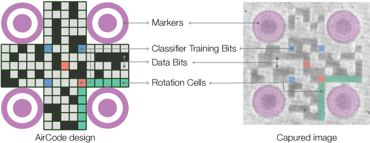
Code Generation
Next, we generate an air pocket structure incorporating markers and bits. Air pockets are organized in a square subsurface region, whose geometric parameters are estimated later in this paper. The layout of the subsurface squares is shown in Figure 8. Four concentric circular markers are placed in the purple areas. The center locations of these markers set up a grid of cells. In each cell, we place a square air pocket to represent 1 or fill with solid printing material to represent 0. Moreover, in a captured image, the entire square region may be rotated. In order to eliminate the rotation, we identify the bottom-right marker by placing air pockets in the cells around it (the green cells in Figure 8). More remarkably, we place a few known bits. The blue cells are always filled with printing material as bits of 1, while the orange cells are filled with air pockets to indicate bits of 0. These bits are scattered on the grid to enable on-the-fly supervised training for our decoding algorithm (see the Decoding step later).
The remaining cells are bits carrying user-specified information. In practice, we use an error-correction scheme (such as the Reed-Solomon coding) [26] to add redundancy in the provided bit string to further improve the robustness of the decoding step. We also note that the grid resolution is user adjustable. A higher resolution accommodates more bits but is more susceptible to noise. In the Results section, we will experimentally validate different resolutions.
In our examples, the physical size of an AirCode tag is around 2cm2cm, allowing the tag to accommodate about 106 bits. But similar to QR codes, the number of bits is extensible. If a larger information capacity is needed, the user can enlarge the tag to store more bits. For example, as shown in the supplementary document, a 5cm5cm tag stores about 500 bits.
5.2 Marker Detection
At the decoding stage, we image the physical object and then process the global-component image to retrieve the embedded tags. The first step of this process is detecting markers, consisting of three stages (A pseudocode of this algorithm is outlined in Algorithm 1 of the supplementary document).
Ellipse Detector locates individual markers from the global component image. The global component image may have non-uniform intensity and noise due to imaging and printing artifacts. We first remove intensity variations by subtracting a two-dimensional quadratic polynomial fitted to the captured object. We also observe that the concentric circular air pockets become blurred and possibly distorted (if the code is not frontally facing the camera). Therefore, we adopt the ellipse detector [31] to detect ellipses on the image. Exploiting the dual conic representation of an ellipse, this method estimates elliptic parameters using image gradient, sidestepping the detection of edge points of the ellipse. This feature particularly suits our problem, as the marker’s boundary are low-contrast and blurry due to the subsurface scattering.
We use the ellipse detector in a multi-scale manner to improve its robustness We build a Gaussian pyramid of the image and detect ellipses at each scale. The detected ellipses are then filtered based on a threshold of the ratio between the major and minor axis lengths (in practice we set the threshold as 1.8). At the end of this stage, we group the centers of the ellipses if they are within a distance (in practice pixels), and compute the averaged center position for each group.
Marker Pruning further filters the remaining ellipse centers and identifies true markers. We exploit the fact that the four markers must form the corners of a planar square. On the image plane, however, their positions can be distorted because of the camera’s perspective projection. But if four centers are indeed the markers, then there must exist a single perspective transformation (the inverse of the camera projection) which restores the four centers into square corners.
We transform this observation into a RANSAC-style (random sample consensus) algorithm [13]. In an iterative process, we pick three ellipse centers, denoted by their 2D coordinates , , and . Since we need at least four points to compute a full projective transformation, we assume that the transform can be approximated by an affine transform. We then compute an affine transformation that aligns three out of the four square corners with the selected centers by solving
where is a matrix accounting for rotation and scale, and is the translation. , , and are three corners of a square (i.e., , , and ). Solving this system yields and , which we then apply to the fourth corner . We repeat this iteration until there exists another ellipse center within a distance threshold from the transformed corner . Then, are identified as the four markers. Typically, RANSAC-style algorithms randomly select points to fit the model and repeat for a predefined number of iterations. Fortunately, we have a small number of ellipses at the end of stage one (typically 8-12). Therefore, we can afford to iterate through all combinations of three ellipse centers until we find marker locations.
Pose Estimation is optional, only needed when one wishes to estimate the pose of the 3D object in addition to decoding the information. Because we know a priori where precisely the markers are in the object, and our marker detection establishes correspondences between markers in the object and markers on the image, we can estimate the object pose (including the rotation and translation) with respect to the camera by solving the classic perspective-4-point-problem in computer vision [37]. In our results, we will demonstrate the use of this pose estimation in a robotic grasping application.
5.3 Decoding
With the four markers identified, we rectify the perspective distortion of the image, establish a grid, and now recognize the bits in individual cells. This recognition also needs to overcome the challenges posed by filament patterns, noise, and uneven lighting. Especially because a grid cell is much smaller than the marker (recall Figure 8), it is more vulnerable to be contaminated by artifacts. As a result, naïve binarization of each cell based on its average pixel value is prone to error.
We choose to use a supervised learning approach to classify grid cells into 0/1 bits. As opposed to conventional supervised learning that requires prepared training data, we train the classifier on the fly. In particular, we use a support vector machine (SVM) because it is lightweight and easy to implement. We take advantage of the known bits that are placed during the encoding stage to train the classifier. These bits, shown as orange and blue cells in Figure 8, form our on-the-fly training set for SVM, where the subscript indexes the cell with a known bit, are the cell’s 0/1 value, and are the training feature vectors. Each element in the vector stores the average of pixels that are pixels away from the center of cell . In practice, the length of the vector is chosen to be pixel number that covers 77 cells centered at . Each feature vector is normalized to adapt to local intensity changes. In the classification phase, feature vectors for unknown bits are constructed in the same manner.
A detail of locating the known bits for training is worth noting. In the captured image, the cell layout may be rotated from what is shown in Figure 8. To eliminate the rotation, recall that only the bottom-right marker has all its surrounding cells filled with air pockets. Thus, on the image, we look for a marker whose surrounding cells have the lowest average pixel value and use it as the bottom-right marker.
6 Imaging Method
To read AirCode tags, we leverage computational imaging method [30] to separate the global and direct component of light transport using structured light patterns from a projector. This method requires only a conventional camera and projector, and the computation is fast. Particularly, we project a checkerboard illumination pattern shifted multiple times, each producing an image. Among the sequence of images, it computes the maximum and minimum values for each pixel, resulting in two images and . Nayar and his coauthors showed that the direct- and global-component images can be estimated from and using the following relationships,
| (1) |
where is the percentage of the activated projector pixels in the sweeping. For checkerboard patterns that we used . We refer to their paper for a detailed derivation of (1) and discuss our addition for specific needs in our problem:
Wavelength Choice
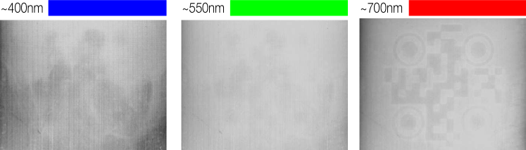
Microscopically, subsurface scattering is caused by the interaction between light waves and the material’s internal irregularities (such as grain boundaries in polycrystalline solids). As a result, the scattering behavior depends on light wavelength [4], and the longer the light wavelength is, the less likely it is scattered in a given material.
In light of this, we take advantage of our full control of the projector and illuminate the object with the longest light wavelength, the red light. This is because the red light is less scattered, and penetrates deeper in the object, resulting in a less blurry global-component image. As shown in Figure 10, we compare the global component images resulted by illuminating with red, green, and blue light. It is evident that the red light produces an image showing the least blurry subsurface structures. In all of our imaging experiments, we use red light unless otherwise specified.
Polarization
Many 3D printed objects (in fact many objects in general) produce specular highlights under illumination (see Figure 11-a). Although specular highlights are caused by reflection which mainly contributes to the direct component of the image, in practice, they also affect the global-component image, because Eq. (1), as an estimation of the global and direct components, cannot separate them completely. We mitigate the negative effect of specular light by placing linear polarizers in front of both the projector and the camera lens [42, 7]. Because the specular reflection preserves most of its polarization but the subsurface scattering depolarizes light, we place the two polarizers that are out of phase with each other to maximally eliminate the specular light. Combining the polarizers and the global-direct separation method, our imaging method is able to detect and recognize the AirCode tags, even in presence of specular highlights (see Figure 11).
7 Determining Air Pocket Parameters
We now present our theoretical analysis that determines air pocket parameters, answering the questions of how large an air pocket should be and how deeply it should be placed under the surface in order to be humanly invisible but machine readable. This analysis is a one-time process for a given fabrication material.
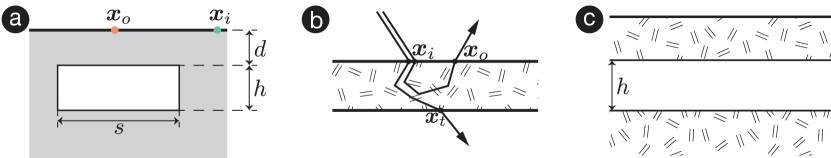
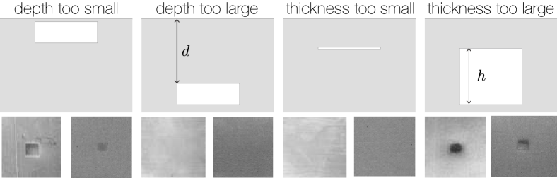
To determine these parameters, we first analyze the change of the material’s surface contrast after introducing subsurface air pockets and exploit studies of human perception of surface contrast. Our goal here is to gain intuition on two design parameters, namely the air pocket depth and thickness (Figure 12-a). Because human sensitivity to surface contrast is not precisely quantified, we do not expect the analysis to give us exact design parameters but rather identify a small range of parameters that we can choose from.
Our analysis is derived from the subsurface scattering light transport model. In this section, we only present the key steps of this analysis while referring to the supplementary document for detailed derivation.
7.1 Subsurface Scattering of Air Pockets
Consider a layer of 3D printing material. When light rays arrive at a position of its top surface, some of them penetrate the surface and are scattered by the substance. Eventually, some light rays pass back out of the material from the top surface, while others escape from the bottom surface (Figure 12-b).
Quantitatively, the subsurface scattering properties of a 3D printing material [10] are described by its reflection and transmission profiles. The reflection profile, , describes the ratio of radiant exitance (light energy) reflected by the surface at to the incident flux at (Figure 12-b), while the transmission profile is defined similarly but for the radiant exitance transmitted through the material layer.
Following the assumptions successfully used for modeling the subsurface scattering of 3D printing materials [18], we consider a laterally infinite layer of homogeneous materials and almost uniform illumination and ignore Fresnel effects. In this case, the reflection and transmission profiles are independent of the incident and outgoing positions but depend only on their distance. Consequently, both and can be written as 1D functions, namely, and .
Intuitively, and indicate how the reflected and transmitted light energy are distributed on the surface. They depend on the thickness of the material layer. But we can measure and at a given thickness, following the method that has proven successful in [18]. Then, the profile at an arbitrary thickness can be analytically calculated (see supplementary document for details).
Scattering Profiles of an Air Layer
Now, consider a laterally infinite air layer of thickness . While the scattering profiles of a 3D printing material can be measured, the scattering profiles of an air layer, to our knowledge, has not been explicitly modeled. As noted in [21], the scattering profiles are typically modeled by assuming light diffusive materials. Yet, air is by no means diffusive; light travels straightforwardly in the air, not scattered at all. In the supplementary document, we derive the transmission profile of an air layer and obtain
Here the constant normalizes to account for the fact that the air layer does not absorb any light. Note that the reflective profile of an air layer is always zero, because an air layer never reflects light at its boundary.
Composition of Air Layer and Scattering Layer
After determining the profiles of a scattering material layer and an air layer, we can composite different layers together and compute the effective scattering profiles. In particular, we are interested in the scattering profiles of a three-layer composite. As illustrated in Figure 12-c, the top layer is a thin layer of scattering material; the second layer is an air layer; the third is a thick substrate made of scattering material also. The effective scattering profiles and of this composition can be numerically evaluated by convolving profiles of individual layers. We present the detailed derivations and formulas in the supplementary document.
Scattering Profiles of Finite Air Pocket Size
The analysis so far considers a laterally infinite air layer. In practice, the air pocket always has a finite lateral size. To model the reflection profile on the surface above an air pocket region (Figure 12-a), we adopt the approximation proposed by Song et al. \shortcitesong2009subedit (also used by previous material fabrication work [18]). This representation defines a local profile at a surface point in order to decompose the reflection profile into , where . Without air layer, the local profile of the homogeneous, thick material volume is . When the laterally infinite air layer exists, the local profile is the profile for the aforementioned, triply layered material (recall Figure 12-c). When the air region has a finite lateral size, the reflection profile across the boundary of an air pocket is approximated as , where is above the air pocket, and is in the solid material region (Figure 12-a).
7.2 Estimating Air Pocket Parameters
We now estimate the range of valid parameters for constructing imperceptible air pockets. To this end, we leverage psychophysical results in visual sensory science.
Human Vision Sensitivity
Particularly relevant to our design of AirCode tags are perceptual studies of contrast sensitivity on blurred blobs [3, 40], because the subsurface air pockets induce a contrast of surface radiosity and the subsurface scattering blurs their shapes. Bijl and his coauthors \shortcitebijl1989visibility discovered, through a series of psychophysical experiments, that (i) the human sensitivity of a Gaussian-like blob is independent of the blob diameter, if the view angle is larger than 20 min arc (i.e., 0.333∘) up to at least 10∘, and that (ii) in this range the (roughly) constant contrast sensitivity threshold is 5%. The contrast is defined as , where and are the maximum and minimum intensity of the blob, respectively.
In our problem, an AirCode tag has a size typically around 2cm. When viewed from a normal distance (e.g., around 75cm) away, the view angle spanned by the codes is around 100 min arc. Exploiting the results of [3], we choose air pocket size and depth such that the resulting contrast (or the change of surface radiosity) is within 5%. This way, by construction the air pockets are invisible to the human eye (as shown in the Results section).
Top Layer Thickness
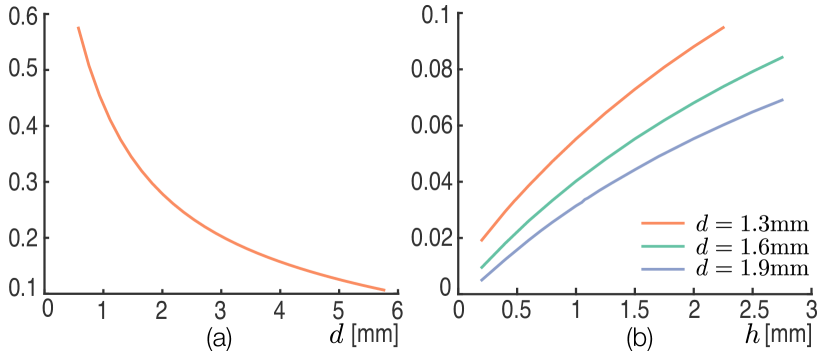
We now estimate the range of the top layer thickness . First, all semitransparent materials absorb light, although sometimes very weakly. If the top layer is too thick, most of the light rays will be absorbed before reaching the air pockets. As increases, the influence of air pockets on the scattered light diminishes. Given a layer of material with a thickness , the amount of light that can transmit through is quantified by its transmissive albedo , computed by integrating the transmission profile over the rotationally extruded 2D plan (i.e., ). Here the subscript in is to emphasize its dependence on the thickness . can be computed using measured scattering profiles (see supplementary document). The transmissive albedo indicates that if a top layer has a thickness , then the influence of air pockets on the surface radiosity is upper bounded by . Thus, we choose a such that , a threshold based on human vision sensitivity (% in practice). For the 3D printing material we use, this leads to mm.
On the other end, the top layer thickness is lower bounded due to the material’s mechanical strength. If is too small, the top layer becomes fragile. In our practice, because is already small, we empirically test a number of (s.t. ) and set mm. We also note that many stress analysis methods exist to help assess the structural strength of a 3D printed model (e.g., see [8]).
Air Pocket Thickness
To estimate the air pocket thickness , we assume almost uniform incoming light. Then the radiosity (intensity of outgoing light) at a surface point is proportional to the surface integral , where is the reflection profile. drops quickly as the distance increases, allowing us to approximate by integrating over a locally flat region.
Suppose that an air pocket of thickness and lateral size is placed at distance (see Figure 12-a). At the surface point above the air pocket, we estimate its radiosity using the reflection profile for finite air pocket size. On the other hand, when there is no air pocket, the surface radiosity is approximately the reflective albedo of the solid thick material. According to the human vision sensitivity studies [3], we define the contrast as , whose value needs to be within the human vision contrast threshold (%) to create imperceptible air pockets. In practice, we use the upper bound, , to estimate the air pocket thickness, because a larger contrast eases machine detection of the codes. See supplementary document for detailed derivation and illustration. In the next section, we verify that this estimation indeed produces invisible yet machine readable tags.
8 Results and Validation
We now present the experiments we conducted to test and validate our AirCode tagging system. We refer to the supplemental video for demonstrating the use of AirCode tags.
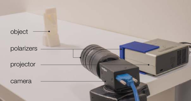
Fabrication and Imaging Setup
We fabricated objects with subsurface air pocket tags using Stratasys Eden260VS, a PolyJet 3D printer with 16-micron layer accuracy (Z direction) and 200-micron planar accuracy (XY plane). We use a white opaque material (VeroWhitePlus, RGD835) and a water-soluble support material (SUP707). This printer can not print voids directly. So we printed the top and bottom layer separately and washed away the support. Cylindrical connectors are added on both sides for assembly (see Figure 2 second column). The reflection and transmission profiles ( and ) are measured using a 3D printed piece of 2mm thickness, following the method [18]. Note that while we use a white opaque material, our analysis is applicable to other homogeneous materials, such as the printing materials of other colors. It is also possible to replace air pockets with other printing materials, and the same analysis for air pocket parameters still applies.
For global component imaging, we project checkerboard illumination patterns using a Mitsubishi PK20 DLP projector (800600 resolution). Images were captured using a Point Grey Grasshopper3 monochrome linear camera (20481536 resolution). We use a monochrome camera to avoid Bayer demosaicing, as we consider scattering at a single wavelength. Figure 9 shows our imaging setup. Under low-light, the output from this camera sensor is noisy. We, therefore, averaged 16 images for each projected checkerboard pattern.
8.1 Validation
We validate our theoretical estimation of air pocket parameters. First, we fabricate pieces with unoptimized air pocket thicknesses and depths. As shown in Figure 13, these arbitrarily chosen parameters lead to either weak signals for imaging system or visible air pockets to our eyes. Our estimation of the parameters is to ensure that the imaging system can detect the air pockets while they remain invisible to naked eyes. In Figure 17 of the supplemental document, we show that the tags using our estimated air pocket parameters remain invisible, even under different lighting conditions and angles.
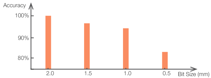
Next, we fabricated four testing pieces with different air pocket widths, 0.5mm, 1mm, 1.5mm, and 2mm, but the same thickness and depth. As shown in the Determining Air Pocket Parameters section, a smaller air pocket width causes fewer changes of surface radiosity. The reduced cell size, on the one hand, allows to accommodate more bits and thereby encode more information. On the other hand, the decreasing contrast in the global component renders the decoding process more difficult. We found that the balance between increasing cell resolution and decreasing decoding robustness is when the cell size is about 1mm (Figure 15). For demonstrating the use of our surface codes, we choose the cell size from 1.5mm to 2mm. In practice, we also use Reed-Solomon code to add 40% redundancy in the encoded bits.
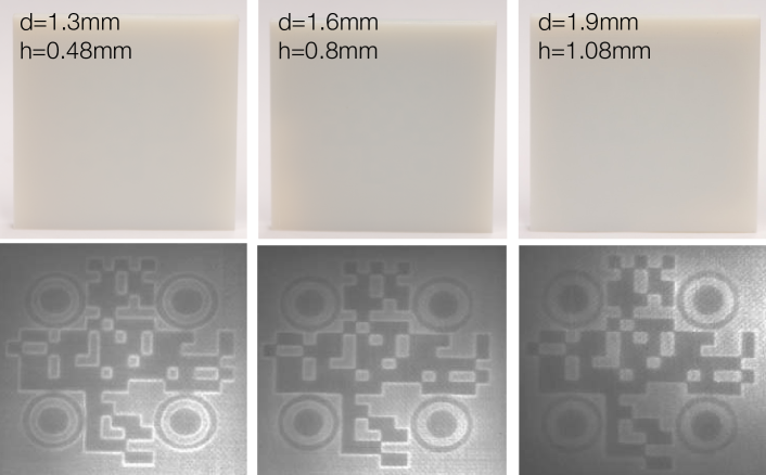
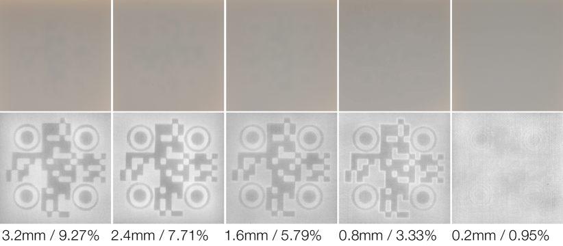
Furthermore, we choose different top layer thickness values and estimate corresponding air layer thickness such that the surface radiosity contrast is about 5% according to our model. The results are shown in Figure 14. In all pieces, the subsurface codes are indeed invisible, while their global-component images all reveal the tags and are machine readable.
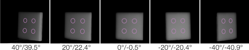
To validate the robustness on orientation, we placed a fabricated piece on a rotary plate and tested the imaging and decoding algorithm with different object orientations. Figure 16 shows that our method is able to read the subsurface codes for rotations in the range of with respect to the camera view direction. We note that this orientation range is much larger than many radiographic techniques. For example, as pointed out in [41], the Terahertz imaging system can only image objects within +/-11∘. Moreover, we measured the accuracy of the pose estimation using subsurface markers (recall the last stage in the Marker Detection section). Our result shows that we can estimate the object rotation angle with an error less than .
9 Discussion and Future Work
We have presented a method that tags physical objects with user-specified information in a digital manufacturing process. These unobtrusive tags are imperceptible to the human eye but recognizable by a computer. This is achieved by placing carefully designed air pocket structures underneath the surface of 3D printed objects.
Although we showed that the global component image is robust against various factors, the capturing process still takes 3-4 minutes. This is because a checkerboard sweeping takes about 10 seconds. To reduce imaging noise, we take multiple sweeps and average them. The imaging time can be shortened by using cameras with less sensor noise or using infrared projectors and cameras. With the constantly improving imaging quality of commodity cameras, we expect that the AirCode tag reading time will be shortened in the near future. Furthermore, we found that by projecting a red image with cross-polarization, we can effectively remove a large number of surface artifacts and specular highlights. However, to recover the global component, we still have to sweep the checkerboard pattern multiple times. It would be an interesting future work to reduce the amount of image captures needed to read the AirCode tags.
Our analysis assumes that the 3D printing material is largely homogeneous and semitransparent. While this assumption is valid for many 3D printing systems that fabricate with plastic materials, other printers cannot produce nearly homogeneous materials. For example, many fused-deposition modeling (FDM) printers deposit relatively thick filaments, and the printed object is not homogeneous. Moreover, it is a common postprocess to paint the surface of a 3D printed object. While our method can account for semitransparent paint, it will fail if the paint is completely opaque. Another limitation is that, unlike traditional optical codes that can be easily replaced if needed, AirCode tags can not be updated after the object is printed, as they are baked into the geometry. But sometimes this is a desired feature to prevent the tags from tampering.
We can place AirCode tags under gently curved surfaces (e.g., the mug grasping in Figure 3) But objects with highly curved shapes present challenges with respect to the air pockets design. In those cases, placing air pockets at a fixed height below the surface with fixed depths will not always produce recognizable tags. We intend to explore other computational methods to compute complicated depth fields that can generate desired global-component effects.
10 Acknowledgements
We thank the anonymous reviewers for their feedback. We are grateful to Arthur Autz for the support of 3D printing facilities, Daniel Miau and Brian A. Smith for the feedback on writing, Henrique Teles Maia for proofreading and narration, Yonghao Yue and Shuang Zhao for rendering suggestions, Klint Qinami and Anne Fleming for proofreading an early draft, Daniel Sims for managing hardware equipment, and Jason Hollaway for imaging and hardware suggestions. This work was supported in part by the NSF Award CAREER-1453101. Dingzeyu Li was partially supported by an Adobe Research Fellowship.
References
- [1]
- [2] Harshit Agrawal, Udayan Umapathi, Robert Kovacs, Johannes Frohnhofen, Hsiang-Ting Chen, Stefanie Müller, and Patrick Baudisch. 2015. Protopiper: Physically Sketching Room-Sized Objects at Actual Scale. In UIST 2015. DOI:http://dx.doi.org/10.1145/2807442.2807505
- [3] P Bijl, JJ Koenderink, and A Toet. 1989. Visibility of blobs with a Gaussian luminance profile. Vision research 29, 4 (1989), 447–456.
- [4] Craig F Bohren and Donald R Huffman. 2008. Absorption and scattering of light by small particles. John Wiley & Sons.
- [5] Varun Perumal C and Daniel J. Wigdor. 2016. Foldem: Heterogeneous Object Fabrication via Selective Ablation of Multi-Material Sheets. In CHI 2016. DOI:http://dx.doi.org/10.1145/2858036.2858135
- [6] Li-Wei Chan, Yi-Ling Chen, Chi-Hao Hsieh, Rong-Hao Liang, and Bing-Yu Chen. 2015. CyclopsRing: Enabling Whole-Hand and Context-Aware Interactions Through a Fisheye Ring. In UIST 2015. DOI:http://dx.doi.org/10.1145/2807442.2807450
- [7] Tongbo Chen, Hendrik P. A. Lensch, Christian Fuchs, and Hans-Peter Seidel. 2007. Polarization and Phase-Shifting for 3D Scanning of Translucent Objects. In CVPR 2007. DOI:http://dx.doi.org/10.1109/CVPR.2007.383209
- [8] Xiang Chen, Changxi Zheng, and Kun Zhou. 2016. Example-Based Subspace Stress Analysis for Interactive Shape Design. PP, 99 (2016).
- [9] Frédéric Cortat. 2004. The Kubelka-Munk theory, applications and modifications. Presentation for the graduate course on Optical properties of Paper, Linkoping University (2004).
- [10] Craig Donner and Henrik Wann Jensen. 2005. Light diffusion in multi-layered translucent materials. ACM Trans. Graph. (2005). DOI:http://dx.doi.org/10.1145/1073204.1073308
- [11] David Espalin, Danny W Muse, Eric MacDonald, and Ryan B Wicker. 2014. 3D Printing multifunctionality: structures with electronics. The International Journal of Advanced Manufacturing Technology 72, 5-8 (2014), 963–978.
- [12] Mark Fiala. 2005. ARTag, a Fiducial Marker System Using Digital Techniques. In CVPR 2005. DOI:http://dx.doi.org/10.1109/CVPR.2005.74
- [13] Martin A Fischler and Robert C Bolles. 1981. Random sample consensus: a paradigm for model fitting with applications to image analysis and automated cartography. Commun. ACM 24, 6 (1981), 381–395.
- [14] Neil Gershenfeld. 2008. Fab: the coming revolution on your desktop–from personal computers to personal fabrication. Basic Books.
- [15] James J Gibson. 2014. The ecological approach to visual perception: classic edition. Psychology Press.
- [16] Jane Greenberg. 2005. Understanding metadata and metadata schemes. Cataloging & classification quarterly 40, 3-4 (2005), 17–36.
- [17] Chris Harrison, Robert Xiao, and Scott E. Hudson. 2012. Acoustic barcodes: passive, durable and inexpensive notched identification tags. In UIST 2012. DOI:http://dx.doi.org/10.1145/2380116.2380187
- [18] Milos̆ Has̆an, Martin Fuchs, Wojciech Matusik, Hanspeter Pfister, and Szymon Rusinkiewicz. 2010. Physical reproduction of materials with specified subsurface scattering. ACM Trans. Graph. (2010). DOI:http://dx.doi.org/10.1145/1833351.1778798
- [19] Haibo Hu, Jian Tang, Hao Zhong, Zheng Xi, Changle Chen, and Qianwang Chen. 2013. Invisible photonic printing: computer designing graphics, UV printing and shown by a magnetic field. Scientific reports 3 (2013).
- [20] Alexandra Ion, Johannes Frohnhofen, Ludwig Wall, Robert Kovacs, Mirela Alistar, Jack Lindsay, Pedro Lopes, Hsiang-Ting Chen, and Patrick Baudisch. 2016. Metamaterial Mechanisms. In UIST 2016. DOI:http://dx.doi.org/10.1145/2984511.2984540
- [21] Henrik Wann Jensen, Stephen R Marschner, Marc Levoy, and Pat Hanrahan. 2001. A practical model for subsurface light transport. In SIGGRAPH 2001. DOI:http://dx.doi.org/10.1145/383259.383319
- [22] Rubaiat Habib Kazi, Tovi Grossman, Cory Mogk, Ryan M. Schmidt, and George W. Fitzmaurice. 2016. ChronoFab: Fabricating Motion. In CHI 2016. DOI:http://dx.doi.org/10.1145/2858036.2858138
- [23] Gierad Laput, Eric Brockmeyer, Scott E. Hudson, and Chris Harrison. 2015a. Acoustruments: Passive, Acoustically-Driven, Interactive Controls for Handheld Devices. In CHI 2015. DOI:http://dx.doi.org/10.1145/2702123.2702414
- [24] Gierad Laput, Xiang ‘Anthony’ Chen, and Chris Harrison. 2015b. 3D Printed Hair: Fused Deposition Modeling of Soft Strands, Fibers, and Bristles. In UIST 2015.
- [25] Dingzeyu Li, David I.W. Levin, Wojciech Matusik, and Changxi Zheng. 2016. Acoustic Voxels: Computational Optimization of Modular Acoustic Filters. ACM Trans. Graph. (2016). DOI:http://dx.doi.org/10.1145/2897824.2925960
- [26] Shu Lin and Daniel J Costello. 2004. Error control coding. Pearson Education India.
- [27] Pedro Lopes, Patrik Jonell, and Patrick Baudisch. 2015. Affordance++: Allowing Objects to Communicate Dynamic Use. In CHI 2015. DOI:http://dx.doi.org/10.1145/2702123.2702128
- [28] James McCrae, Nobuyuki Umetani, and Karan Singh. 2014. FlatFitFab: interactive modeling with planar sections. In UIST 2014. DOI:http://dx.doi.org/10.1145/2642918.2647388
- [29] Stefanie Mueller, Tobias Mohr, Kerstin Guenther, Johannes Frohnhofen, and Patrick Baudisch. 2014. faBrickation: fast 3D printing of functional objects by integrating construction kit building blocks. In CHI 2014. DOI:http://dx.doi.org/10.1145/2556288.2557005
- [30] Shree K. Nayar, Gurunandan Krishnan, Michael D. Grossberg, and Ramesh Raskar. 2006. Fast separation of direct and global components of a scene using high frequency illumination. ACM Trans. Graph. (2006). DOI:http://dx.doi.org/10.1145/1141911.1141977
- [31] Jean-Nicolas Ouellet and Patrick Hébert. 2009. Precise ellipse estimation without contour point extraction. Mach. Vis. Appl. 21, 1 (2009), 59–67.
- [32] Marios Papas, Christian Regg, Wojciech Jarosz, Bernd Bickel, Philip Jackson, Wojciech Matusik, Steve Marschner, and Markus H. Gross. 2013. Fabricating translucent materials using continuous pigment mixtures. ACM Trans. Graph. (2013). DOI:http://dx.doi.org/10.1145/2461912.2461974
- [33] Huaishu Peng, Rundong Wu, Steve Marschner, and François Guimbretière. 2016. On-The-Fly Print: Incremental Printing While Modelling. In CHI 2016. DOI:http://dx.doi.org/10.1145/2858036.2858106
- [34] Valkyrie Savage, Andrew Head, Björn Hartmann, Dan B. Goldman, Gautham J. Mysore, and Wilmot Li. 2015. Lamello: Passive Acoustic Sensing for Tangible Input Components. In CHI 2015. DOI:http://dx.doi.org/10.1145/2702123.2702207
- [35] Ying Song, Xin Tong, Fabio Pellacini, and Pieter Peers. 2009. SubEdit: a representation for editing measured heterogeneous subsurface scattering. ACM Trans. Graph. (2009). DOI:http://dx.doi.org/10.1145/1531326.1531337
- [36] Andrew Spielberg, Alanson P. Sample, Scott E. Hudson, Jennifer Mankoff, and James McCann. 2016. RapID: A Framework for Fabricating Low-Latency Interactive Objects with RFID Tags. In CHI 2016. DOI:http://dx.doi.org/10.1145/2858036.2858243
- [37] Richard Szeliski. 2010. Computer vision: algorithms and applications. Springer Science & Business Media.
- [38] Alexander Teibrich, Stefanie Müller, François Guimbretière, Robert Kovacs, Stefan Neubert, and Patrick Baudisch. 2015. Patching Physical Objects. In UIST 2015. DOI:http://dx.doi.org/10.1145/2807442.2807467
- [39] Tatyana Vasilevitsky and Amit Zoran. 2016. Steel-Sense: Integrating Machine Elements with Sensors by Additive Manufacturing. In CHI 2016. DOI:http://dx.doi.org/10.1145/2858036.2858309
- [40] RJ Watt and MJ Morgan. 1983. The recognition and representation of edge blur: evidence for spatial primitives in human vision. Vision research 23, 12 (1983), 1465–1477.
- [41] Karl D. D. Willis and Andrew D. Wilson. 2013. InfraStructs: fabricating information inside physical objects for imaging in the terahertz region. ACM Trans. Graph. (2013). DOI:http://dx.doi.org/10.1145/2461912.2461936
- [42] L. B. Wolff. 1989. Using polarization to separate reflection components. In CVPR 1989. DOI:http://dx.doi.org/10.1109/CVPR.1989.37873
- [43] Shengdong Zhao, Koichi Nakamura, Kentaro Ishii, and Takeo Igarashi. 2009. Magic cards: a paper tag interface for implicit robot control. In CHI 2009. DOI:http://dx.doi.org/10.1145/1518701.1518730
Supplemental Document:
11 Background in Subsurface Scattering
When light rays arrive at the material surface, some of them penetrate the surface and are scattered by the substance, before passing back out of the material. The subsurface scattering has been widely modeled by the bidirectional subsurface scattering reflectance distribution function (BSSRDF) an eight-dimensional function, denoted as , that determines the outgoing radiance at a surface point in direction using
where is the incoming radiance arriving at a surface point from direction , and is the angle between the surface normal direction and . Following the assumptions successfully used in the fabrication of subsurface scattering materials [18], we consider homogeneous materials and almost uniform illumination, and ignore Fresnel effects. Then, the BSSRDF reduces to a 1D radial function, . Moreover, we adopt the notions of reflection and transmission profiles [10], denoted as and , respectively. is the ratio of the radiant exitance reflected by the surface to the incident flux, while is defined similarly but for the radiant exitance transmitted through the material volume. and are related to through and , where “+” and “-” indicate whether the incoming and outgoing point are on the same or opposite side of the material volume.
With these notions, we can express the reflection and transmission profile of a multi-layered material using the profiles of its individual layer components. Consider two laterally infinite slabs of constant thickness (see Figure 12-b). Let and () denote the profiles of these two slabs. Attaching the second slab to the bottom side of the first one results in a new slab with the scattering profiles related to and through convolutions [10]. In short, the scattering profiles of the new slab are
| (2) |
where and are the Hankel transform—the equivalent of Fourier transform for radially symmetric functions—of and , respectively [18]. When there is not confusion, we will refer and also as the reflection and transmission profiles.
12 Computing Transmission Profile
We follow the Kubelka-Munk theory to compute the transmission profile of a laterally infinite slab with a thickness [9, 18]. We measure the reflection and transmission profiles and of a slab with a thickness , and compute their Hankel transforms and . Then, and of an arbitrary thickness can be computed as
where and are hyperbolic functions, and
Here both and are constant values, computed by
The limits here can be computed by repeatedly halving the thickness (starting from and ) using the relationship (2).
13 Pseudocode for Marker Detection
14 More Experimental Analysis
Figure 17 demonstrates the proposed AirCode remains imperceptible under extreme lighting conditions.
As mentioned in the main text, AirCode naturally extends to handle higher data capacity, similar to QR code design. In Figure 18, a larger tag is designed and printed. More than 500 bits are encoded in this 5cm by 5cm AirCode tag.
To analyze the visibility quantitatively, we fabricate pieces with different air pocket thicknesses and depths. To show As the air thickness decreases, the air layer transmission profile Consequently, the air pockets become less visible, as shown in Figure 20. If the air pocket is too thin (0.2mm), the resulting contrast cannot be detected by the algorithm, as the signal-to-noise ratio is too low.
The transmissive albedo provides us insight on setting the maximum of : it indicates that if the top layer has a thickness , then the influence of air pockets on the surface radiosity is upper bounded by . Thus, we choose a such that , a threshold based on human vision sensitivity ( in practice). For example, for the 3D printing material we use, this leads to . In Figure 19-b, we consider an air pocket with a lateral size and visualize the change of the contrast value with respect to and .