Kirigami Actuators
Abstract
Thin elastic sheets bend easily and, if they are patterned with cuts, can deform in sophisticated ways. Here we show that carefully tuning the location and arrangement of cuts within thin sheets enables the design of mechanical actuators that scale down to atomically–thin 2D materials. We first show that by understanding the mechanics of a single, non–propagating crack in a sheet we can generate four fundamental forms of linear actuation: roll, pitch, yaw, and lift. Our analytical model shows that these deformations are only weakly dependent on thickness, which we confirm with experiments at centimeter scale objects and molecular dynamics simulations of graphene and MoS2 nanoscale sheets. We show how the interactions between non–propagating cracks can enable either lift or rotation, and we use a combination of experiments, theory, continuum computational analysis, and molecular dynamics simulations to provide mechanistic insights into the geometric and topological design of kirigami actuators.
Deformations that bend a material without stretching involve a very low amount of stored elastic energy, and therefore present an opportunity to enable morphing at minimal energetic cost. The potential to exploit these energetically favorable and soft modes has recently emerged with kirigami-based thin sheets Reis (2015); Seffen (2016); Rafsanjani and Bertoldi (2017); Bico et al. (2017), in which the introduction of cuts has been utilized to give unique structural properties and non-linear behavior, such as auxeticity Virk et al. (2013); Scarpa et al. (2013); Tang and Yin (2017), significantly enhanced stretchability Shyu et al. (2015); Vachicouras et al. (2017), flexible electronic devices Zhang et al. (2015), and topologically guided morphings Sadoc et al. (2012); Charvolin and Sadoc (2011); Sadoc et al. (2013); Castle et al. (2014); Sussman et al. (2015); Chen et al. (2016). In this work, we present a variety of kirigami actuators whose dynamical pattern formation is controllable. We develop a novel form of non-linear control-response relationships in kirigami geometries through the conversion of linear displacement imposed on the boundary of the thin sheet into a range of predictable motions.
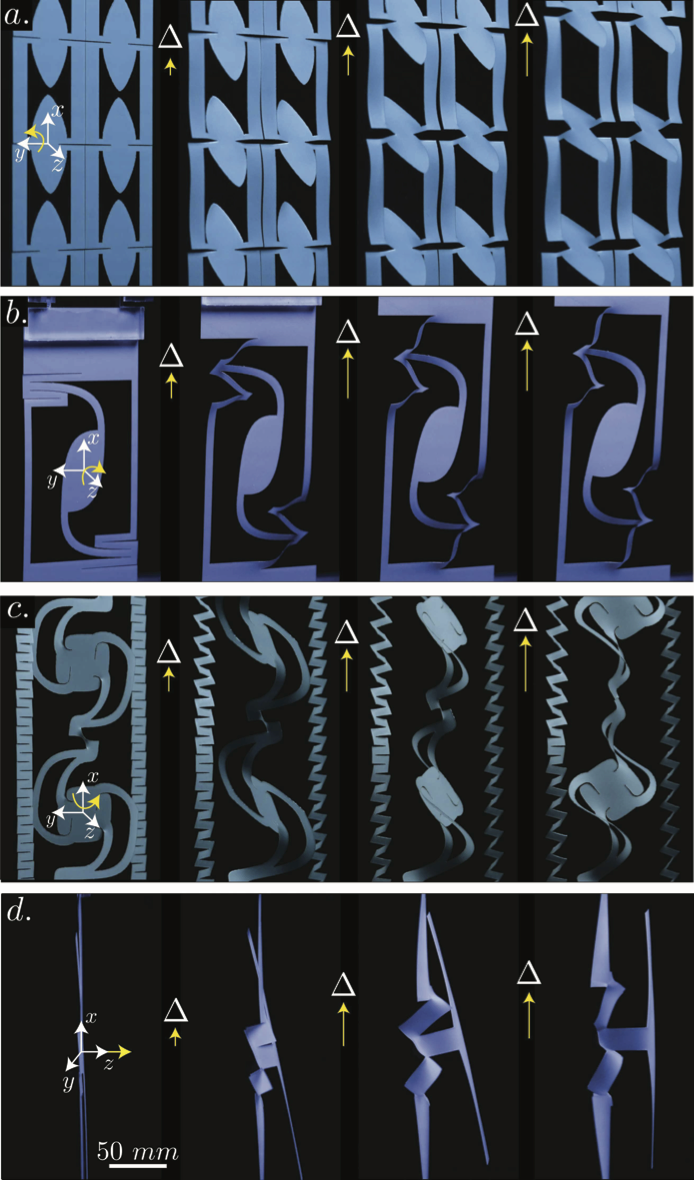
The four fundamental modes depicted in figure 1, namely roll (rotation about –axis), pitch (rotation about –axis), yaw (rotation about –axis), and lift (–axis out–of–plane displacement), arise from linear actuation, and they may in principle be combined to generate any motion in 3D space. To demonstrate this designing goal, we create three orthogonal rotations and a vertical out–of–plane displacement and show the mechanism for understanding how these emerge from the coupled behavior of individual cuts. We provide a theory that captures the main large scale features in the mechanics of these structures, and demonstrate that similar actuators can be realized in suspended 2D materials, such as graphene and MoS2 Qi et al. (2014); Blees et al. (2015). Moreover, a full characterization of the out–of–plane displacement that occurs as a result of a single cut in a thin sheet allows us to derive a scaling law that shows a robust link between simulation and experiment on length–scales ranging over six orders of magnitude. Because kirigami actuators are scale–invariant, our findings can be applied to tailor the microstructure and functionality of mechanical metamaterials across the technological spectrum of length scales ranging from the nanoscale (NEMS) Qi et al. (2014); Blees et al. (2015); Cai et al. (2016); Han et al. (2017), the microscale (MEMS) Song et al. (2015); Xu et al. (2016); Rogers et al. (2016); Baldwin and Meng (2017), and the macroscale Saito et al. (2011); Sareh and Rossiter (2012); Zhang and Dai (2014); Lamoureux et al. (2015).
The complex behavior of kirigami actuators arises from functionalizing cracks in thin plates. In other words, when a material is thin enough, cracks under tension may cause the system to buckle before failure through crack propagation Hui et al. (1998); Brighenti (2005). Therefore, a deeper understanding of the mechanics of a single non–propagating crack on thin sheets is needed. Let us consider a cut of length centered with respect to the sheet’s length and width , and parallel to the clamped edges of the sheet (figure 2). The sheet thickness is small, such that . Applying a uniaxial extension perpendicular to the crack causes the sheet to buckle out–of–plane at a critical force . The typical deflection size is given by a maximum amplitude centered between the crack tips, and this shape decays back to nearly flat before reaching the clamped boundaries (figure 2). This characteristic shape occurs on each side of the crack, such that the shape may be symmetric or antisymmetric about the plane aligned with the crack, normal to the initially flat surface—these two modes, respectively, correspond to stress intensity factors of bending and transverse shear Hui et al. (1998); Zehnder and Viz (2005). We shall here focus our analysis on the symmetric kind, as the typical size of both out–of–plane deformations must be of the same order of magnitude. The critical force needed to trigger this instability is given by , which depends on the ratio of the crack to sheet width, (figure 2). Since the instability results from an in–plane compressive zone (figure 2) around the internal boundary along the crack Adda-Bedia and Ben Amar (2001); Brighenti (2005), this problem will be approximated by a beam of length . Therefore, is shown to collapse on a single curve (figure 2) when the experimental data and simulation results are normalized by the characteristic buckling force , where is the Young’s modulus of the material. This will become evident in equation (5), where we derive as the critical amount of in–plane compression at the buckling threshold.
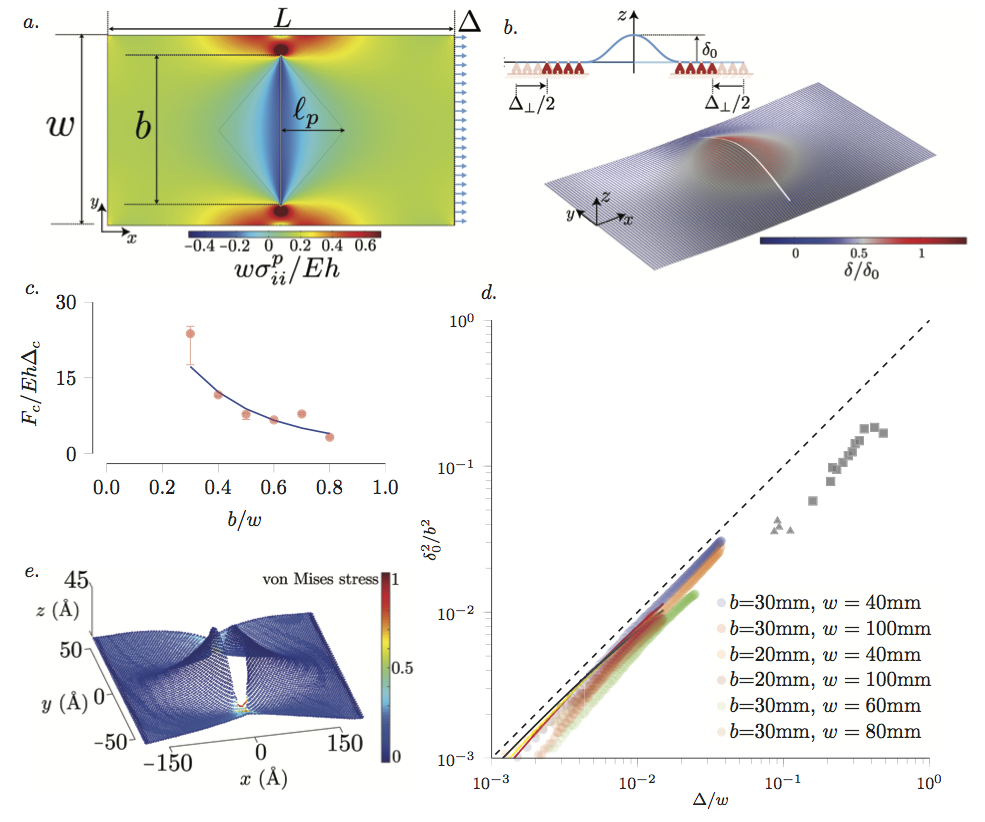
To describe the post–buckled shape, we consider two regimes: the in–plane stretching dominated response to an applied extension normal to the single cut, and the out–of–plane state, where the buckling threshold is reached in the stress relief zone and the system becomes bending dominated. This loading condition induces a crack opening mode described by the mode I stress intensity factor, , which for a large plate in a state of uniform uniaxial stress is , where is the tensile stress acting on the edge of the sheet Bazant and Cedolin (2010). From fracture mechanics Bazant and Cedolin (2010), it is stablished that the stress scales with the radius of curvature of the cut: . To estimate the tension in the sheet, we note that stresses concentrate near the crack and, in view of St. Venant’s Principle Muskhelishvili (2013), it approaches an average value at a distance of about width away from the crack. This approximation is also validated from the fact that beyond a sheet length to width ratio of about , the maximum deflection of the crack reaches a constant value indicating that, beyond a certain point, the sheet length does not contribute to the crack deformation. Therefore, we expect the tension in the sheet to scale as . In our experiments we take for the crack radius. Therefore, the stress in the sheet becomes The elastic strain energy due to stretching scales as , where is the area of the sheet, which reduces to
| (1) |
If we consider the sheet to be dominated by stretching, i.e. by initially neglecting bending energy, the total potential energy is given as , where is the work done by the extension . Taking the work as the force times the extension , where is lateral strain of the sheet, and minimizing the total potential energy, , gives a relation for the lateral contraction,
| (2) |
Note that equation (2) is effectively a scaling of Poisson’s contraction and sets up the base state for the in–plane solution. We now calculate the next order contribution by allowing the stresses in the compressive zone to reduce the total energy through out–of–plane bending. The calculation is simplified by treating the problem as a 1D buckling of the free boundary along the crack (figure 2), where both stretching and bending energies are required to provide the right balance. This next order contribution is obtained as a minimizer of a dimensionally reduced model, along the arc-length of the cut, given by
| (3) |
where the new measure of strain is geometrically non-linear, , and is the deflection. This yields a classic result for the maximum amplitude:
| (4) |
where is related to the ratio between bending rigidity, , and stretching rigidity, , as follows: . Inserting the in–plane compression result of equation (2) into (4) gives a scaling for the maximum crack deflection,
| (5) |
Equation 5 shows a higher order dependency on the sheet thickness to crack length ratio, implying the invariance of these deformations from the macro to the nanoscale. To confirm this relationship, experiments were performed with single cuts in mylar films (Biaxially-oriented polyethylene terephthalate—BoPET) to measure the maximum deflection as a function of extension for a given crack size and sheet width (see methods section). Finite Element Method (FEM) simulations with the same material parameters were also performed (see methods section). Additionally, we carried out Molecular Dynamics (MD) simulations of suspended graphene monolayers (see methods section). Figure 2 shows the dimensionless deflection data for the experiments and simulations, along with the scaling prediction from equation 5, confirming a very strong agreement across six orders of magnitude.
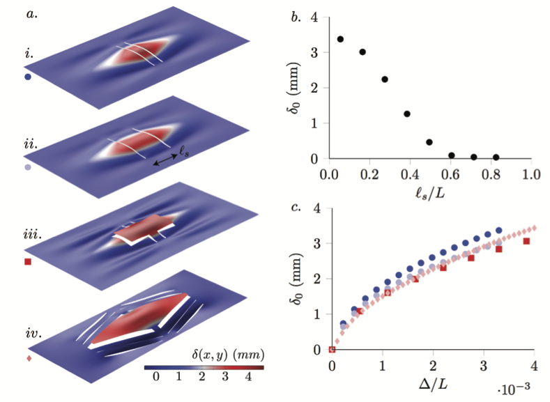
In order to generate simple actuators that can become the building blocks for more complex structures, such as mechanical metamaterials, we must quantify how multiple cracks will interact to generate motion of points on the sheet. Since the behavior of a single crack is well described by equation (5), the simplest extension is two parallel cracks of length separated by distance . When is small, these cracks interact to generate vertical lift of the sheet between them (figure 3– & ). However, the deflection of the center point of the sheet drops off quickly as the spacing between the cracks is increased, making it difficult to lift a large amount of surface area (figure 3). Keeping small while increasing the area of the sheet that is lifted can be accomplished by extending a portion of each crack towards the clamped boundaries (figure 3–). This relies on the same buckling mechanism that governs the single crack behavior, producing nearly the same amount of lift as the two parallel cracks (figure 3). These additional cuts also introduce wrinkles on the sheet, which can be avoided by introducing cuts that provide room for in–plane compression (figure 3–). With this arrangement of cuts, we demonstrate how these parallel cracks can become building blocks for generating lift of a large, localized area.
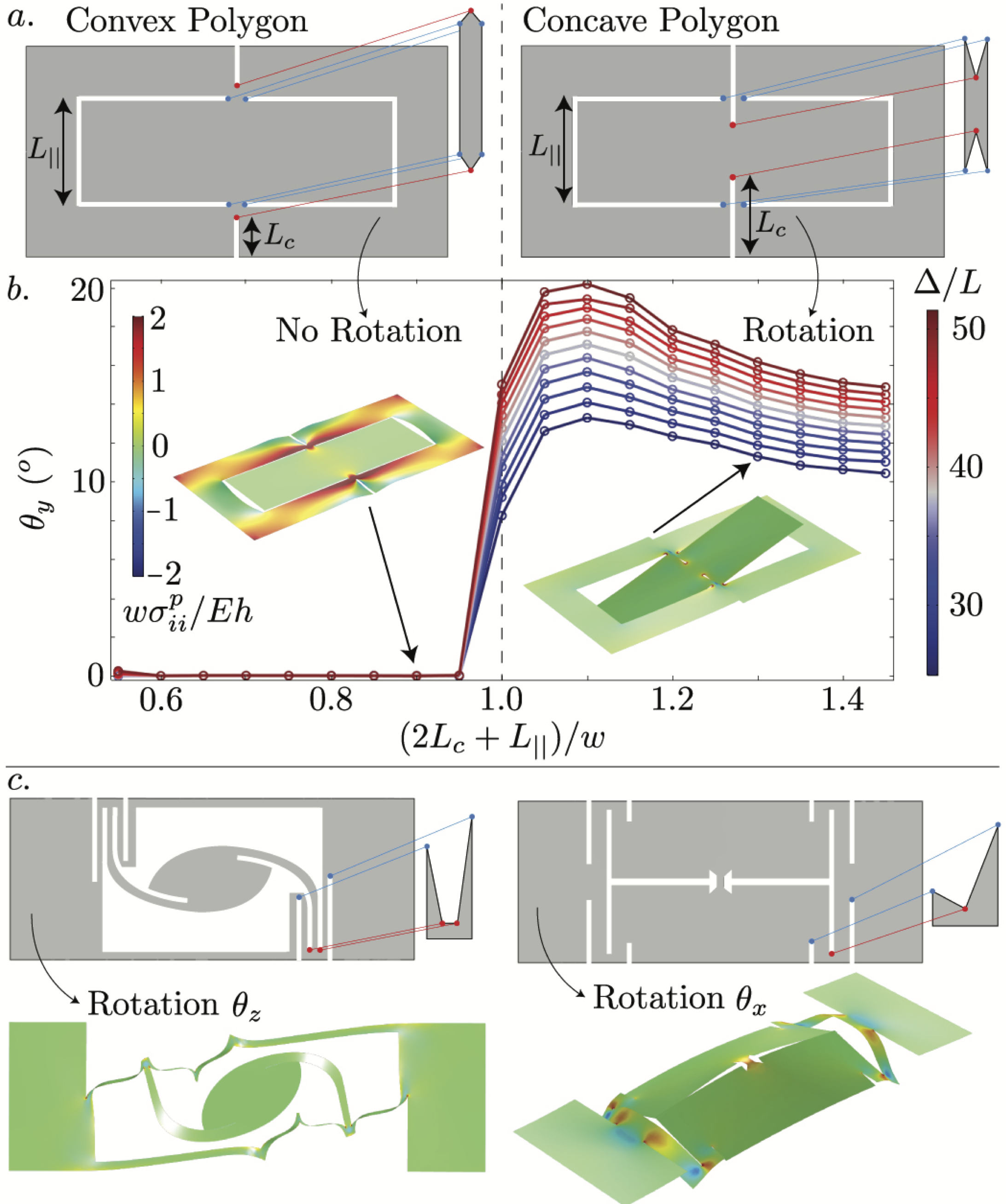
We note that the four crack tips of the two parallel cracks in figure 3– form a rectangular unit cell (convex polygon) and generate lift in the sheet. This rudimentary shape is identified quantitatively by following the lines of tension that connect two neighboring cracks, and the convexity of the unit cell signifies how much stretching within the sheet can be transferred into a crack opening displacement. Convex shapes constrain the sheet to induce vertical lift, while concave shapes have the freedom to rotate. To illustrate this idea, we focus on the pitch mode. We performed a post–buckling analysis through FEM simulations for the geometry in figure 4, while varying crack length , thus allowing us to scan unit cell shapes from convex to concave. Denoting as the cut length parallel to the clamped boundary, we refer to the ratio as a measure of convexity. The target shape strongly depends on this parameter’s transition: lift of the outer portion of the sheet occurs when the unit cell is convex, i.e. , while rotation about the –axis occurs when it is concave, i.e. (figure 4). Generating rotation about the and axes follows the same principle—concave unit cells enable rotation (figure 4). In these more complex configurations, there is coupling between two unit cells within the sheet. While an intricate model of the coupling between multiple unit cells is beyond the scope of this work, it is clear from the schematics and post–buckled shapes that the concave unit cells locally enable rotation about the and axes.
Figure 4 indicates that the convexity of the unit cell formed by the locally interacting crack tips can generate either lift or rotation. We provide further insight through quantifying the magnitude of these kirigami–based motions by measuring the lift or rotation as a function of relative strain (figure 5). Here we show that a portion of the sheet can achieve a vertical displacement nearly 50 times the sheet thickness. Since there is no plastic deformation and the cracks do not propagate, these deformations are reversible. The stiffness of the sheets designed to provide rotation varies widely. Rotations about the (pitch) and (roll) axes reach about 60 degrees after a moderate amount of extension, while the in–plane rotation about –axis requires a significant amount of extension to reach 30 degrees of rotation. Figure 5 shows good agreement between the experimental measurements for the macroscale designs of lift (diamonds for ) and rotation (triangles for , disks for , and squares for ) and the FEM simulations (dashed line for , orange for , red for , and blue for ).
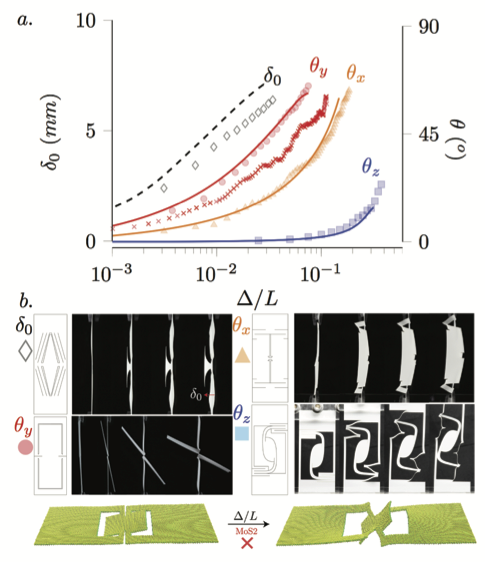
The results from figure 2 suggest that these actuator designs should scale down to 2D materials. From a MoS2 monolayer, we tested the simplest nanoactuator requiring only one unit cell for rotation about the –axis, i.e. the pitch mode shown at the bottom in figure 5. We obtained a rigid rotation due to its higher bending modulus than that of graphene Jiang et al. (2013). We applied an extension perpendicular to the crack and measured the rotation of the inner ribbon about the –axis (figure 5, red x’s). At small , there is good agreement between the macroscale results and the nanoscale simulations, and eventually the three actuators achieve nearly the same maximum value of . While the behavior is qualitatively similar across several orders of magnitude in sheet thickness, it is clear that the agreement for the 2D kirigami is qualitative rather than quantitative. Specifically, the fact that the rotation that is observed in the 2D kirigami is smaller for the same strains than the bulk system suggests that the 2D system may undergo more stretching than the bulk system, a point also made recently by Grosso and Mele Grosso and Mele (2015). Therefore, additional analysis of the 2D material kirigami actuators is necessary to quantitatively replicate the macroscale actuator designs.
Finally, we return to the actuators in figure 1. Through replicating the mechanism in figure 4, we see rotation about the –axis of all cells (Figure 1). This indicates that building blocks can go beyond mechanism design towards the development of mechanical metamaterials. Furthermore, the interactions between multiple cuts can enable portions of a thin sheet to rotate one complete revolution about the –axis the extension axis (figure 1), while coupling unit cells that cause rotation and lift generates sheets that first rotate about the –axis and subsequently lift in the direction (figure 1). What remains is to better understand how building blocks can be combined to generate targeted behaviors—an inverse problem that can begin by considering the simple geometric model we present here.
We have addressed two fundamental problems that are pivotal to connecting kirigami actuators to practical designs for engineering applications: scale-invariant behavior and a robust geometric mechanism for actuator design. While the kirigami mechanics has been unified over six orders of magnitude in sheet thickness, the shape of a unit cell formed by locally interacting crack tips provides a geometric mechanism to induce either lift or rotation. What we present has the potential to offer rational designing tools for dynamical assembling of complex geometries Zhang et al. (2015); Lamoureux et al. (2015), and we hope that this spontaneous generation of shapes emerging from quasi-static actuation comes to complement inverse design algorithms that have been proposed for lattice-based kirigami Castle et al. (2014); Sussman et al. (2015). As it has been previously mentioned, the cracks do not propagate in the experiments performed here, thus the process remains entirely reversible. In order to maintain this reversibility in systems utilizing materials with lower yield stress, cracks can be made with a larger crack tip radius , thus lowering the stress intensity factor, . The scaling found here is robust under such a modification since a few multiples of only yield a pre-factor in front of equation (5), thus preserving the same power-law. It is also noted that the propagation of interacting cracks can be manipulated by their initial geometry Cortet et al. (2008); Dalbe et al. (2015), such interactions could be utilized to increase the functionality of the kirigrami structures and/or give a predictable response to strain beyond that which causes crack propagation. There may also be significant scientific benefits to demonstrating kirigami actuation in 2D materials. From a basic science perspective, kirigami provides an ideal platform to study the localization of electronic states, or the coupling of 2D quantum dots Bahamon et al. (2016). Alternatively, these structures offer significant opportunities for flexible, lightweight band-gap engineered optoelectronic materials whose performance can be reversibly changed and manipulated over a wide range of the optical spectrum by locally varying the strain Castellanos-Gomez et al. (2013); Tsai et al. (2015); He et al. (2013); Lloyd et al. (2016); Feng et al. (2012); Conley et al. (2013); Johari and Shenoy (2012); Kotov et al. (2012).
Methods Section
Fabrication: Mylar (BoPET) films were purchased from McMaster–Carr (Mylar, 8567K96), and had a thickness of mm. To relieve any residual stress in the films, apparent from their natural curvature, we annealed the films in the oven at 85oC under the weight of thick metal sheets for 2 hours, resulting in flat sheets. Vector patterns were drawn in Adobe Illustrator CS6, and cut with an Epilog Mini 24, 75W laser cutter in vector mode, at 80 speed and 10 power. Sheet widths of mm, 60mm, 80mm, and 100mm were used, and sheet lengths of mm to 200mm in linear increments of 20mm were used. For the single cut experiments, cut lengths ranging from mm to 70mm were used. The cut mylar films were adhered to 3mm thick acrylic sheets (McMaster–Carr, acrylic, 8560K191) with cyanoacrylate glue (McMaster-Carr, Loctite 403, 74765A53), which served as the clamped boundary conditions for the films.
Mechanical Measurements: Uniaxial tension tests were performed by clamping the mylar sheets to the Instron 5943 mechanical testing system, using a 500N load cell. Displacement–controlled tests were performed at a rate of 0.15mm/min to a maximum extension of 1.5mm. Since the mylar did not experience inelastic strains, actuation was reversible, and 3 tests were run for each sample. Actuator deformation was captured from the side with a microscopic lens (Navitar Zoom 6000) attached to a Nikon D610 camera, and from the front using a Nikon D610 camera with a Micro-NIKKOR 105mm f/2.8 Lens, a Nikon 55mm f/2.8 Lens, and a high contrast Rosco Color Filter (B&H Photo Video, ROCEK1212). The critical buckling force was determined from identifying both the slope change in the force vs. displacement curve, and the out–of–plane deflection from the microscopic imaging of the crack profile.
Finite Element Method (FEM): FEM simulations were undertaken using COMSOL Multiphysics 5.2 COMSOL (Last accessed 14 July 2017) along with the Structural Mechanics Module. Shell Mechanics and Plates were the environments within COMSOL in which all of our studies were performed. A geometry matching those used in the experiment was created in COMSOL’s Design Module. Mesh refinement studies were undertaken to ensure convergence of the results. For the single cut geometry in figure 2, the sheet was modeled as an isotropic elastic thin sheet with thickness of mm, Young’s Modulus GPa, and Poisson’s ratio . The results shown in figure 2 were attained through linear buckling studies with varying thickness in the range and the values . The in–plane results shown in figure 2 and post-buckling results in figures 2, 3, and 4 were calculated from a stationary study with displacement () controlled analysis. In order to induce out–of–plane symmetry breaking, we added random small imperfections (ten orders of magnitude smaller than the sheet thickness) to the initial surface. The parameters in figure 2 varied and lay in the ranges and . For the results shown in figure 5, linear buckling studies were undertaken with the boundary at fixed in space while the boundary at had an imposed displacement of in the direction. Both of these boundaries were not permitted to rotate. All other boundaries were free. Small imperfections in the form of the first eigenmodes were then added to the initially flat geometry through use of MeshPerturb 1.0 Saha and Culpepper (2014). These imperfect geometries were then used for the stationary studies with the same boundary conditions and the same mesh density as was used in the linear studies.
Molecular Simulations: We used Sandia-developed open source LAMMPS Molecular Dynamics Simulator to simulate graphene sheets Lammps (2012). To describe the carbon-carbon interactions, we used AIREBO potential Stuart et al. (2000) as has been used previously in atomistic study of graphene kirigami Qi et al. (2014). The cutoffs for the Lennard-Jones and the REBO term in AIREBO potential are chosen to be 2 Å and 6.8 Å, respectively. For MoS2 actuators we used the Stillinger-Weber potential developed by Jiang Jiang (2015), which we have previously employed to study MoS2 kirigami Hanakata et al. (2016). Graphene with a single crack and the MoS2 actuator were first relaxed for 50–200 ps at 4.2K within the NVT (fixed number of atoms , volume , and temperature ) ensemble. Non-periodic boundary conditions were applied in all three directions. After the relaxation, the strains were applied by displacing both ends at a uniform rate.
Author contributions
M.A.D. and D.P.H. conceived the study and proposed the research; M.A.D. and D.R.K. performed the mathematical modeling and FEM in consultation with D.P.H.; M.P.M. and D.P.H. performed the experiments in consultation with M.A.D.; P.Z.H., D.K.C., and H.S.P. performed the Molecular Simulations studies; M.A.D. and D.P.H. wrote the main article; and all authors jointly edited the entire article.
Acknowledgements
M.A.D. is grateful to M. Adda-Bedia, J. Bico, B. Roman, and K. Seffen for many insightful discussions. M.A.D. would also like to thank ENS-Lyon and ESPCI-Paris for hosting the author during part of the development of this manuscript and funding from the 4-VA program for collaborative research at JMU. D.P.H. is grateful to the National Science Foundation (CMMI CAREER–1454153) for financial support. M.A.D., D.R.K., and D.P.H. would like to thank I. Metta for the useful discussions at the start of this project. D.K.C. acknowledges the Aspen Center for Physics, which is supported by National Science Foundation grant PHY-1607611, where part of this work was completed. D.R.K. acknowledges funding from Academy of Finland.
Conflict of interest
The authors declare no conflict of interest.
References
- Reis (2015) P. M. Reis, Journal of Applied Mechanics 82, 111001 (2015).
- Seffen (2016) K. A. Seffen, Physical Review E 94, 033003 (2016).
- Rafsanjani and Bertoldi (2017) A. Rafsanjani and K. Bertoldi, Physical Review Letters 118, 084301 (2017).
- Bico et al. (2017) J. Bico, E. Lepoivre, H. Bense, E. Reyssat, and B. Roman, Bulletin of the American Physical Society 62 (2017).
- Virk et al. (2013) K. Virk, A. Monti, T. Trehard, M. Marsh, K. Hazra, K. Boba, C. D. L. Remillat, F. Scarpa, and I. R. Farrow, Smart Materials and Structures 22, 084014 (2013).
- Scarpa et al. (2013) F. Scarpa, M. Ouisse, M. Collet, and K. Saito, Journal of Vibration and Acoustics 135, 041001 (2013).
- Tang and Yin (2017) Y. Tang and J. Yin, Extreme Mechanics Letters 12, 77 (2017).
- Shyu et al. (2015) T. C. Shyu, P. F. Damasceno, P. M. Dodd, A. Lamoureux, L. Xu, M. Shlian, M. Shtein, S. C. Glotzer, and N. A. Kotov, Nature materials 14, 785 (2015).
- Vachicouras et al. (2017) N. Vachicouras, C. M. Tringides, P. B. Campiche, and S. P. Lacour, Extreme Mechanics Letters 15, 63 (2017).
- Zhang et al. (2015) Y. Zhang, Z. Yan, K. Nan, D. Xiao, Y. Liu, H. Luan, H. Fu, X. Wang, Q. Yang, J. Wang, et al., Proceedings of the National Academy of Sciences 112, 11757 (2015).
- Sadoc et al. (2012) J.-F. Sadoc, N. Rivier, and J. Charvolin, Acta Crystallographica Section A: Foundations of Crystallography 68, 470 (2012).
- Charvolin and Sadoc (2011) J. Charvolin and J.-F. Sadoc, Biophysical Reviews and Letters 6, 13 (2011).
- Sadoc et al. (2013) J.-F. Sadoc, J. Charvolin, and N. Rivier, Journal of Physics A: Mathematical and Theoretical 46, 295202 (2013).
- Castle et al. (2014) T. Castle, Y. Cho, X. Gong, E. Jung, D. M. Sussman, S. Yang, and R. D. Kamien, Physical Review Letters 113, 1 (2014).
- Sussman et al. (2015) D. M. Sussman, Y. Cho, T. Castle, X. Gong, E. Jung, S. Yang, and R. D. Kamien, Proceedings of the National Academy of Sciences p. 201506048 (2015).
- Chen et al. (2016) B. G.-g. Chen, B. Liu, A. A. Evans, J. Paulose, I. Cohen, V. Vitelli, and C. D. Santangelo, Physical review letters 116, 135501 (2016).
- Qi et al. (2014) Z. Qi, D. K. Campbell, and H. S. Park, Physical Review B 90, 245437 (2014).
- Blees et al. (2015) M. K. Blees, A. W. Barnard, P. A. Rose, S. P. Roberts, K. L. McGill, P. Y. Huang, A. R. Ruyack, J. W. Kevek, B. Kobrin, D. A. Muller, et al., Nature 524, 204 (2015).
- Cai et al. (2016) K. Cai, J. Luo, Y. Ling, J. Wan, and Q.-H. Qin, Scientific Reports 6 (2016).
- Han et al. (2017) T. Han, F. Scarpa, and N. L. Allan, Thin Solid Films (2017).
- Song et al. (2015) Z. Song, X. Wang, C. Lv, Y. An, M. Liang, T. Ma, D. He, Y.-J. Zheng, S.-Q. Huang, H. Yu, et al., Scientific reports 5, 10988 (2015).
- Xu et al. (2016) L. Xu, X. Wang, Y. Kim, T. C. Shyu, J. Lyu, and N. A. Kotov, ACS nano 10, 6156 (2016).
- Rogers et al. (2016) J. Rogers, Y. Huang, O. G. Schmidt, and D. H. Gracias, Mrs Bulletin 41, 123 (2016).
- Baldwin and Meng (2017) A. Baldwin and E. Meng, in Micro Electro Mechanical Systems (MEMS), 2017 IEEE 30th International Conference on (IEEE, 2017), pp. 227–230.
- Saito et al. (2011) K. Saito, F. Agnese, and F. Scarpa, Journal of intelligent material systems and structures 22, 935 (2011).
- Sareh and Rossiter (2012) S. Sareh and J. Rossiter, Smart Materials and Structures 22, 014004 (2012).
- Zhang and Dai (2014) K. Zhang and J. S. Dai, Journal of Mechanisms and Robotics 6, 021007 (2014).
- Lamoureux et al. (2015) A. Lamoureux, K. Lee, M. Shlian, S. R. Forrest, and M. Shtein, Nature Communications 6, 8092 (2015).
- Hui et al. (1998) C. Y. Hui, A. T. Zehnder, and Y. K. Potdar, International Journal of Fracture 93, 409 (1998).
- Brighenti (2005) R. Brighenti, Thin-Walled Structures 43, 209 (2005).
- Zehnder and Viz (2005) A. T. Zehnder and M. J. Viz, Applied Mechanics Reviews 58, 37 (2005).
- Adda-Bedia and Ben Amar (2001) M. Adda-Bedia and M. Ben Amar, Physical Review Letters 86, 5703 (2001).
- Bazant and Cedolin (2010) Z. P. Bazant and L. Cedolin, Stability of Structures: Elastic, Inelastic, Fracture and Damage Theories (World Scientific, 2010), ISBN 9789814317030.
- Muskhelishvili (2013) N. I. Muskhelishvili, Some Basic Problems of the Mathematical Theory of Elasticity (Springer Netherlands, 2013), ISBN 9789401730341.
- Jiang et al. (2013) J.-W. Jiang, Z. Qi, H. S. Park, and T. Rabczuk, Nanotechnology 24, 435705 (2013).
- Grosso and Mele (2015) B. F. Grosso and E. J. Mele, Phys. Rev. Lett. 115, 195501 (2015).
- Cortet et al. (2008) P.-P. Cortet, G. Huillard, L. Vanel, and S. Ciliberto, Journal of Statistical Mechanics: Theory and Experiment 2008, P10022 (2008).
- Dalbe et al. (2015) M.-J. Dalbe, J. Koivisto, L. Vanel, A. Miksic, O. Ramos, M. Alava, and S. Santucci, Physical review letters 114, 205501 (2015).
- Bahamon et al. (2016) D. A. Bahamon, Z. Qi, H. S. Park, V. M. Pereira, and D. K. Campbell, Phys. Rev. B 93, 235408 (2016), URL https://link.aps.org/doi/10.1103/PhysRevB.93.235408.
- Castellanos-Gomez et al. (2013) A. Castellanos-Gomez, R. Roldán, E. Cappelluti, M. Buscema, F. Guinea, H. S. van der Zant, and G. A. Steele, Nano letters 13, 5361 (2013).
- Tsai et al. (2015) M.-Y. Tsai, A. Tarasov, Z. R. Hesabi, H. Taghinejad, P. M. Campbell, C. A. Joiner, A. Adibi, and E. M. Vogel, ACS applied materials & interfaces 7, 12850 (2015).
- He et al. (2013) K. He, C. Poole, K. F. Mak, and J. Shan, Nano letters 13, 2931 (2013).
- Lloyd et al. (2016) D. Lloyd, X. Liu, J. W. Christopher, L. Cantley, A. Wadehra, B. L. Kim, B. B. Goldberg, A. K. Swan, and J. S. Bunch, Nano letters 16, 5836 (2016).
- Feng et al. (2012) J. Feng, X. Qian, C.-W. Huang, and J. Li, Nature Photonics 6, 866 (2012).
- Conley et al. (2013) H. J. Conley, B. Wang, J. I. Ziegler, R. F. Haglund Jr, S. T. Pantelides, and K. I. Bolotin, Nano letters 13, 3626 (2013).
- Johari and Shenoy (2012) P. Johari and V. B. Shenoy, ACS nano 6, 5449 (2012).
- Kotov et al. (2012) V. N. Kotov, B. Uchoa, V. M. Pereira, F. Guinea, and A. C. Neto, Reviews of Modern Physics 84, 1067 (2012).
- COMSOL (Last accessed 14 July 2017) COMSOL, http://www.comsol.com/comsol-multiphysics (Last accessed 14 July 2017).
- Saha and Culpepper (2014) S. K. Saha and M. L. Culpepper (2014).
- Lammps (2012) Lammps, http://lammps.sandia.gov (2012).
- Stuart et al. (2000) S. J. Stuart, A. B. Tutein, and J. A. Harrison, The Journal of chemical physics 112, 6472 (2000).
- Jiang (2015) J.-W. Jiang, Nanotechnology 26, 315706 (2015).
- Hanakata et al. (2016) P. Z. Hanakata, Z. Qi, D. K. Campbell, and H. S. Park, Nanoscale 8, 458 (2016).