Antiferromagnetic skyrmion crystals: generation, topological Hall and topological spin Hall effect
Abstract
Skyrmions are topologically nontrivial, magnetic quasi-particles, that are characterized by a topological charge. A regular array of skyrmions—a skyrmion crystal (SkX)—features the topological Hall effect (THE) of electrons, that, in turn, gives rise to the Hall effect of the skyrmions themselves. It is commonly believed that antiferromagnetic skyrmion crystals (AFM-SkXs) lack both effects. In this Rapid Communication, we present a generally applicable method to create stable AFM-SkXs by growing a two sublattice SkX onto a collinear antiferromagnet. As an example we show that both types of skyrmion crystals—conventional and antiferromagnetic—exist in honeycomb lattices. While AFM-SkXs with equivalent lattice sites do not show a THE, they exhibit a topological spin Hall effect. On top of this, AFM-SkXs on inequivalent sublattices exhibit a nonzero THE, which may be utilized in spintronics devices. Our theoretical findings call for experimental realization.
Introduction.
Skyrmions Skyrme (1962); Bogdanov and Yablonskii (1989); Bogdanov and Hubert (1994); Rößler et al. (2006); Mühlbauer et al. (2009) are small magnetic quasiparticles, which are usually caused by the Dzyaloshinskii-Moriya interaction Dzyaloshinsky (1958); Moriya (1960), but they have been produced by other mechanisms Nagaosa and Tokura (2013), like frustrated exchange interactions Okubo et al. (2012), as well. While single skyrmions are envisioned to be used as “bits” in data storage devices Fert et al. (2013); Wiesendanger (2016); Romming et al. (2013); Hsu et al. (2017); Zhang et al. (2015a, b); Jiang et al. (2015); Boulle et al. (2016); Seki et al. (2012); Woo et al. (2016), which provide durability of data due to topological protection Nagaosa and Tokura (2013), skyrmion crystals (SkXs)—regular arrays of skyrmions—are best known for exhibiting the topological Hall effect (THE) of electrons Neubauer et al. (2009); Schulz et al. (2012); Kanazawa et al. (2011); Lee et al. (2009); Li et al. (2013); Bruno et al. (2004); Göbel et al. (2017, 2017); Ndiaye et al. (2017), that, in turn, gives rise to the skyrmion Hall effect (SkHE; also present in isolated skyrmions) Nagaosa and Tokura (2013); Zang et al. (2011); Jiang et al. (2017); Litzius et al. (2017).
From the perspective of applications in data storage devices, the SkHE is undesirable. Thus, the concept of antiferromagnetic (AFM) skyrmions has been developed Barker and Tretiakov (2016); Zhang et al. (2016a); Fujita and Sato (2017); Jin et al. (2016): skyrmions on two sublattices in which the spins on one sublattice are (mutually) reversed. As a result, both THE and SkHE vanish Barker and Tretiakov (2016). Because no periodic antiferromagnetic skyrmion crystal (AFM-SkX) is known yet, surrogate systems consisting of two skyrmion layers with opposite winding have been investigated Zhang et al. (2016b); Buhl et al. (2017).
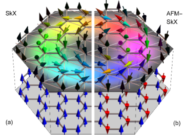
In this Rapid Communication, we predict the generation of stable AFM-SkXs by coupling a bipartite skyrmion material to a collinear antiferromagnetic layer (Fig. 1b). The interlayer interaction acts as staggered magnetic field, which flips the spins of the SkX on one sublattice. The approach is generally applicable, as it can turn every established phase of conventional SkXs into an AFM-SkX phase, irrespective of the skyrmion-generating mechanism. As an example, we apply the method to frustrated spins on a honeycomb lattice, i. e., two triangular sublattices that exhibit SkXs via frustrated exchange interactions (cf. Ref. Okubo et al., 2012).
If both sublattices of the AFM-SkX are equivalent, there is no THE. However, we find a topological spin Hall effect (TSHE). Since the TSHE arises in a single two-dimensional layer, it is clearly distinguished from that in the surrogate system discussed in Refs. Zhang et al., 2016b; Buhl et al., 2017. For inequivalent sublattices the THE becomes also nonzero, which may become considerable for applications, once the predicted existence of AFM-SkXs has been realized experimentally.
Generation of AFM skyrmion crystals.
First, we present our approach to create a stable AFM-SkX starting from a known SkX phase. We take two copies of that two-dimensional system and couple them to a collinear antiferromagnet. This inverts the spins of one sublattice and yields a stable AFM-SkX with the parameters of the initial SkX. This approach is generally applicable, as it does not depend on the SkX-generating mechanism.
As an example we take a honeycomb lattice featuring two triangular sublattices, and , which both exhibit a SkX produced by frustration (Ref. Okubo et al., 2012). The sublattice skyrmions are stabilized by an external magnetic field and by thermal fluctuations; they can be understood as superposition of three degenerate spin spirals which form the ground state for zero temperature and no magnetic field. To make the sublattice SkXs match we add a weak inter-sublattice coupling (results for a realistic inter-sublattice coupling are shown below).
The system is described by the Hamiltonian Okubo et al. (2012)
| (1) |
in which are Heisenberg exchange constants ( and site indices). We take into account nearest- () and third-nearest-neighbor exchange () within each sublattice and add inter-sublattice coupling (). The Zeeman term provides coupling to the external magnetic field along the direction. All energies are given in units of a global constant . The magnetic configuration is computed by classical Monte Carlo simulations ( spin of unit length).
As a prerequisite, a weak inter-sublattice coupling (see caption of Fig. 1) ensures that the skyrmion-center locations of and adjust to each other. This way the lattice constant of the SkX and the magnetic phase diagram remain almost unchanged (with respect to the uncoupled SkXs Okubo et al. (2012)). An exemplary result for a conventional SkX is shown in Fig. 2a.
To create an AFM-SkX the spins of one sublattice have to be reversed. This would require an unrealistic staggered magnetic field . Instead we mimic it by placing the skyrmion lattice on a collinear antiferromagnet with strong out-of-plane uniaxial anisotropy (Fig. 1b). For matching sublattices the inter-sublattice coupling has to be chosen negative. The resulting AFM-SkXs on top of an antiferromagnet (Fig. 1b) have the same energy and exhibit the same geometry (compare Fig. 2a with b and c) as the SkXs (Fig. 1a).
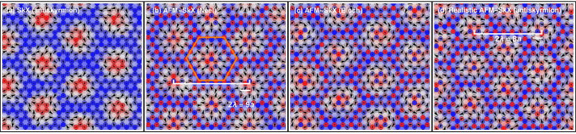
Special properties of the SkXs attributed to frustration survive our approach: helicity (i. e., Néel- or Bloch-type skyrmions), winding (i. e., skyrmions or antiskyrmions with topological charge ), and skyrmion-center locations are not fixed for both SkXs and AFM-SkXs (Fig. 2).
In real materials the sublattices and are strongly coupled; . Nevertheless, our simulations show that AFM-SkXs can still be stabilized (Fig. 2d) but lattice constant, stabilizing field, and temperature of the initial sublattice skyrmions can not be carried over to the resulting AFM-SkX.
A synopsis: AFM-SkXs can be produced by coupling a two-sublattice SkX to an antiferromagnetic layer (Fig. 1b). This approach is valid irrespective of the physical mechanism that stabilizes the SkX (frustration Okubo et al. (2012), Dzyaloshinskii-Moriya interaction Do Yi et al. (2009) or anisotropy Leonov and Mostovoy (2015)). The novel AFM-SkX state motivates to calculate the THE and TSHE.
Electron transport in (AFM) skyrmion textures.
In a tight-binding model the interaction of electrons with a (AFM) skyrmion texture is described by the Hamiltonian Hamamoto et al. (2015)
| (2) |
( and creation and annihilation operators, respectively; vector of Pauli matrices). The hopping from site to site is quantified by , the coupling to the skyrmion texture by .
The transverse charge conductivity at the Fermi energy is calculated from the Kubo formula Nagaosa et al. (2010)
| (3) |
[BZ Brillouin zone; ]. The sum runs over all bands . is the Fermi distribution function at temperature ; , , and denote the electron charge, the Planck constant, and the Boltzmann constant, respectively. The Berry curvature (a general version that also describes spin transport),
is determined from the eigenvectors with eigenenergies of the -dependent Hamiltonian Gradhand et al. (2012). For the topological Hall conductivity in skyrmion textures, the matrix is a unit matrix. If lies within the band gap above the th band, is proportional to the winding number Hatsugai (1993a, b), , that is the accumulation of the integer Chern numbers .
For the spin conductivity, accounts for the alignment of the electron spin with the skyrmion texture. Additionally, Eq. (3) has to be multiplied by to reflect spin instead of charge transport. For the spin conductivity in AFM-SkXs the sign of the entries are reversed for the sublattice with negative net magnetization, since a locally parallel aligned spin means spin up or down in the respective sublattice.
In the following, we utilize skyrmion textures on the honeycomb lattice that enter Eq. (2) by superposing three spin spirals, as in Ref. Okubo et al., 2012 (Fig. 1a). An AFM-SkX is then constructed by reversing the spins in one of the sublattices (Fig. 1b). These textures are idealized versions of those generated from (Fig. 2).
Topological Hall effects in skyrmion crystals.
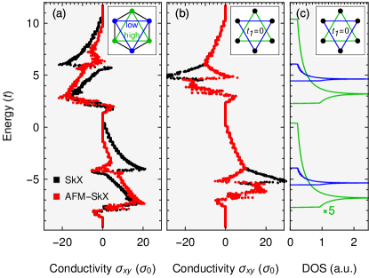
For the topological Hall effect (THE) in a SkX (Fig. 1a), we consider two generic cases: (i) nearest-neighbor hopping strength and second-nearest neighbor hopping strength as well as (ii) and (cf. the insets in Fig. 3).
For large coupling to the skyrmion texture ( in Fig. 3), the band structure is energetically split into two blocks (rigidly shifted by ). In each of the blocks, the electron spin is aligned parallel (lower block) or antiparallel (upper block) to the texture. As a result, the respective energy-dependent transverse conductivities have opposite sign and exhibit (almost) identical shapes Göbel et al. (2017).
The above qualitative picture is nicely reproduced by the computed THE of case (i) (black line in Fig. 3a; cf. Ref. Göbel et al., 2017). Within each block, the conductivity is antisymmetric because the sublattices are equivalent. The bands of the lower (upper) block carry Chern number (), except for bands close to a van Hove singularity of the zero-field band structure (at ), as is explained in Refs. Göbel et al., 2017 and Göbel et al., 2017 (at the associated energies the Fermi lines change their character from electron to hole pockets). The latter bands compensate the accumulated large Chern numbers of all other bands in their block and bring about a sign change in .
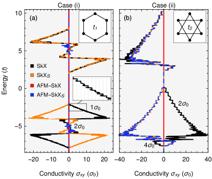
For case (ii) (two uncoupled triangular sublattices Göbel et al. (2017)), we find the separation into two blocks as well. Every band is almost degenerate (minimal splitting due to for bands of both sublattices; see Fig. S2 in the Supplemental Material 111See Supplemental Material at [URL will be inserted by publisher] for band structures of the SkX and AFM-SkX). Thus, the conductivity shows steps in units of (Fig. 3b), that is twice as large as in case (i).
The alignment of the spins (parallel or antiparallel) with the skyrmion texture results in a transverse spin-polarized current Yin et al. (2015). The magnitude of the spin conductivity corresponds to the charge conductivity (in the block-separated case for large coupling ). Spin and charge current are inseparable.
Topological spin Hall effect in AFM skyrmion crystals.
We proceed with the generic cases for the AFM-SkXs (Fig. 1b). Case (i) exhibits no considerable transverse transport because the emergent field fluctuates around zero, yielding zero net field. In case (ii) the topological Hall conductivity is zero as well; this is explained by the two sublattices having opposite emergent fields. However, we find a topological spin Hall effect.
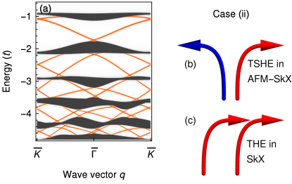
The bands of case (ii) are two-fold degenerate because the sublattices are equivalent []. The spin is aligned parallel (lower block) or antiparallel (upper block) to the texture of the respective sublattice. Since the sublattices are decoupled (), the electrons are localized exclusively in either sublattice. This causes a spin-up current (from the sublattice with positive net magnetization) and a spin-down current (from the other sublattice, with negative net magnetization). Hence, a TSHE occurs which is identical to the (spin-polarized) THE in the SkX (Fig. 4b,c; cf. the blue and orange lines in Fig. 3b). For the AFM-SkX we find a pure spin current; the THE is zero.
In each of the bulk-band gaps the number of right–propagating edge states is identical to that of left-propagating ones (Fig. 4a): there is no charge transport, i. e., no THE. Since the edge states ‘live’ on different sublattices they carry opposite spin because their spins are aligned with the associated sublattice texture. The emergent fields of the individual sublattices have opposite signs; thus, they deflect electrons of opposite spin into opposite directions (Fig. 4b). The result is a TSHE. Recall that in a SkX the identical emergent fields of the sublattices deflect electrons of the same spin into the same direction (Fig. 4c); hence the spin conductivities for AFM-SkX and SkX are identical, but in the AFM-SkX there is no effective transverse charge current.
For intermediate and more general cases, i. e., and , the results lie between case (i) and (ii) (see Fig. S1 in the Supplemental Material 222See Supplemental Material at [URL will be inserted by publisher] for topological (spin) Hall conductivities for the case .). The TSHE in an AFM-SkX is nonzero as long as . The THE is zero in any case.
Summarizing, one finds a THE of spin-polarized electrons in SkXs (Fig. 1a) and a TSHE in AFM-SkXs (Fig. 1b), that is, the analogues to Hall and spin Hall physics in a single two-dimensional layer, as distinguished from the surrogate multilayer system of Refs. Zhang et al. (2016b); Buhl et al. (2017).
Topological Hall effect in asymmetric AFM skyrmion crystals.
Having discussed generic cases, we proceed with sublattice-asymmetric AFM-SkXs (e.g., in crystals consisting of two different elements), which is modeled by setting and by differing on-site energies, . The topological Hall conductivity exhibits the band-block separation (Figs. 5a and b) and is nonzero in any case.
To clarify these findings we consider the tight-binding Hamiltonian (2) without spin texture (), with parameters as in Fig. 5b (uncoupled sublattices). The density of states (DOS) of the resulting two bands (one band per sublattice) is shown in Fig. 5c. Comparing SkX and AFM-SkX, the sublattice skyrmions on (green curve) have the same winding, while for (blue) they have opposite winding. Therefore, in regions in which the two zero-field bands (green and blue) do not overlap in energy, the topological Hall conductivities of a SkX and an AFM-SkX are identical.
The contribution of the narrow band (blue) has to be subtracted (added) from (to) the conductivity corresponding to the green band for the AFM-SkX (SkX) because of the opposite (identical) winding of the sublattice skyrmion (see Ref. Göbel et al., 2017).
For nonzero and (Fig. 5a) a sublattice separation of the bands is no longer given, but the conductivity does not change qualitatively. It is even possible that the topological Hall conductivity of an AFM-SkX exceeds that of a SkX (see Fig. S3 in the Supplemental Material 333See Supplemental Material at [URL will be inserted by publisher] for topological Hall conductivities for the case .).
Conclusion.
In this Rapid Communication, we predict the generation of stable antiferromagnetic skyrmion crystals. These systems can in principle be realized on any bipartite lattice — provided the individual sublattices exhibit a conventional skyrmion crystal (irrespective of the generating mechanism) — by growing it onto a collinear antiferromagnet (Fig. 1b).
For equivalent sublattices, there is no topological Hall effect but a topological spin Hall effect. Furthermore, asymmetric antiferromagnetic skyrmion crystals (i. e., with inequivalent sublattices) exhibit a topological Hall effect. These findings are valid also for metastable single antiferromagnetic skyrmions; see Refs. Zhang et al., 2016a; Barker and Tretiakov, 2016; Fujita and Sato, 2017. Very recently ferrimagnetic skyrmions have been found in GdFeCo films Woo et al. (2017). The magnetic moments of the two sublattices are inequivalent and a topological Hall effect is measurable, which corroborates our analysis.
Besides the potential of stable AFM-SkXs for applications, the Hamiltonian of Eq. (1) motivates further theoretical investigations. An example is transport via magnons, studied in stable magnetic configurations. One may compare the topological magnon Hall effects in skyrmion crystals Mook et al. (2017) with that in antiferromagnetic skyrmion crystals.
Acknowledgements.
This work is supported by Priority Program SPP 1666 of Deutsche Forschungsgemeinschaft (DFG).References
- Skyrme (1962) T. H. R. Skyrme, Nuclear Physics 31, 556 (1962).
- Bogdanov and Yablonskii (1989) A. Bogdanov and D. Yablonskii, Zh. Eksp. Teor. Fiz 95, 182 (1989).
- Bogdanov and Hubert (1994) A. Bogdanov and A. Hubert, J. Magn. Magn. Mater. 138, 255 (1994).
- Rößler et al. (2006) U. Rößler, A. Bogdanov, and C. Pfleiderer, Nature 442, 797 (2006).
- Mühlbauer et al. (2009) S. Mühlbauer, B. Binz, F. Jonietz, C. Pfleiderer, A. Rosch, A. Neubauer, R. Georgii, and P. Böni, Science 323, 915 (2009).
- Dzyaloshinsky (1958) I. Dzyaloshinsky, J. Phys. Chem. Sol. 4, 241 (1958).
- Moriya (1960) T. Moriya, Phys. Rev. 120, 91 (1960).
- Nagaosa and Tokura (2013) N. Nagaosa and Y. Tokura, Nature Nanotechnology 8, 899 (2013).
- Okubo et al. (2012) T. Okubo, S. Chung, and H. Kawamura, Phys. Rev. Lett. 108, 017206 (2012).
- Fert et al. (2013) A. Fert, V. Cros, and J. Sampaio, Nature Nanotechnol. 8, 152 (2013).
- Wiesendanger (2016) R. Wiesendanger, Nature Reviews Materials 1, 16044 (2016).
- Romming et al. (2013) N. Romming, C. Hanneken, M. Menzel, J. E. Bickel, B. Wolter, K. von Bergmann, A. Kubetzka, and R. Wiesendanger, Science 341, 636 (2013).
- Hsu et al. (2017) P.-J. Hsu, A. Kubetzka, A. Finco, N. Romming, K. von Bergmann, and R. Wiesendanger, Nature Nanotechnol. 12, 123 (2017).
- Zhang et al. (2015a) X. Zhang, M. Ezawa, and Y. Zhou, Scientific Reports 5, 9400 (2015a).
- Zhang et al. (2015b) X. Zhang, Y. Zhou, M. Ezawa, G. Zhao, and W. Zhao, Scientific Reports 5, 11369 (2015b).
- Jiang et al. (2015) W. Jiang, P. Upadhyaya, W. Zhang, G. Yu, M. B. Jungfleisch, F. Y. Fradin, J. E. Pearson, Y. Tserkovnyak, K. L. Wang, O. Heinonen, et al., Science 349, 283 (2015).
- Boulle et al. (2016) O. Boulle, J. Vogel, H. Yang, S. Pizzini, D. de Souza Chaves, A. Locatelli, T. O. Menteş, A. Sala, L. D. Buda-Prejbeanu, O. Klein, et al., Nature Nanotechnol. 11, 449 (2016).
- Seki et al. (2012) S. Seki, X. Yu, S. Ishiwata, and Y. Tokura, Science 336, 198 (2012).
- Woo et al. (2016) S. Woo, K. Litzius, B. Krüger, M.-Y. Im, L. Caretta, K. Richter, M. Mann, A. Krone, R. M. Reeve, M. Weigand, et al., Nature Materials 15, 501 (2016).
- Neubauer et al. (2009) A. Neubauer, C. Pfleiderer, B. Binz, A. Rosch, R. Ritz, P. Niklowitz, and P. Böni, Phys. Rev. Lett. 102, 186602 (2009).
- Schulz et al. (2012) T. Schulz, R. Ritz, A. Bauer, M. Halder, M. Wagner, C. Franz, C. Pfleiderer, K. Everschor, M. Garst, and A. Rosch, Nature Phys. 8, 301 (2012).
- Kanazawa et al. (2011) N. Kanazawa, Y. Onose, T. Arima, D. Okuyama, K. Ohoyama, S. Wakimoto, K. Kakurai, S. Ishiwata, and Y. Tokura, Phys. Rev. Lett. 106, 156603 (2011).
- Lee et al. (2009) M. Lee, W. Kang, Y. Onose, Y. Tokura, and N. Ong, Phys. Rev. Lett. 102, 186601 (2009).
- Li et al. (2013) Y. Li, N. Kanazawa, X. Yu, A. Tsukazaki, M. Kawasaki, M. Ichikawa, X. Jin, F. Kagawa, and Y. Tokura, Phys. Rev. Lett. 110, 117202 (2013).
- Bruno et al. (2004) P. Bruno, V. Dugaev, and M. Taillefumier, Phys. Rev. Lett. 93, 096806 (2004).
- Göbel et al. (2017) B. Göbel, A. Mook, J. Henk, and I. Mertig, Phys. Rev. B 95, 094413 (2017).
- Göbel et al. (2017) B. Göbel, A. Mook, J. Henk, and I. Mertig, New J. Phys. 19, 063042 (2017).
- Ndiaye et al. (2017) P. B. Ndiaye, C. A. Akosa, and A. Manchon, Phys. Rev. B 95, 064426 (2017).
- Zang et al. (2011) J. Zang, M. Mostovoy, J. H. Han, and N. Nagaosa, Phys. Rev. Lett. 107, 136804 (2011).
- Jiang et al. (2017) W. Jiang, X. Zhang, G. Yu, W. Zhang, X. Wang, M. B. Jungfleisch, J. E. Pearson, X. Cheng, O. Heinonen, K. L. Wang, et al., Nature Physics 13, 162 (2017).
- Litzius et al. (2017) K. Litzius, I. Lemesh, B. Krüger, P. Bassirian, L. Caretta, K. Richter, F. Büttner, K. Sato, O. A. Tretiakov, J. Förster, et al., Nature Physics 13, 170 (2017).
- Barker and Tretiakov (2016) J. Barker and O. A. Tretiakov, Phys. Rev. Lett. 116, 147203 (2016).
- Zhang et al. (2016a) X. Zhang, Y. Zhou, and M. Ezawa, Scientific Reports 6, 24795 (2016a).
- Fujita and Sato (2017) H. Fujita and M. Sato, Phys. Rev. B 95, 054421 (2017).
- Jin et al. (2016) C. Jin, C. Song, J. Wang, and Q. Liu, Applied Physics Letters 109, 182404 (2016).
- Zhang et al. (2016b) X. Zhang, Y. Zhou, and M. Ezawa, Nature Communications 7, 10293 (2016b).
- Buhl et al. (2017) P. M. Buhl, F. Freimuth, S. Blügel, and Y. Mokrousov, physica status solidi (RRL)-Rapid Research Letters 11, 1700007 (2017).
- Do Yi et al. (2009) S. Do Yi, S. Onoda, N. Nagaosa, and J. H. Han, Phys. Rev. B 80, 054416 (2009).
- Leonov and Mostovoy (2015) A. Leonov and M. Mostovoy, Nature Comms. 6, 8275 (2015).
- Hamamoto et al. (2015) K. Hamamoto, M. Ezawa, and N. Nagaosa, Phys. Rev. B 92, 115417 (2015).
- Nagaosa et al. (2010) N. Nagaosa, J. Sinova, S. Onoda, A. MacDonald, and N. Ong, Rev. Mod. Phys. 82, 1539 (2010).
- Gradhand et al. (2012) M. Gradhand, D. Fedorov, F. Pientka, P. Zahn, I. Mertig, and B. Györffy, Journal of Physics: Condensed Matter 24, 213202 (2012).
- Hatsugai (1993a) Y. Hatsugai, Phys. Rev. B 48, 11851 (1993a).
- Hatsugai (1993b) Y. Hatsugai, Phys. Rev. Lett. 71, 3697–3700 (1993b).
- Yin et al. (2015) G. Yin, Y. Liu, Y. Barlas, J. Zang, and R. K. Lake, Phys. Rev. B 92, 024411 (2015).
- Henk and Schattke (1993) J. Henk and W. Schattke, Computer Physics Communications 77, 69 (1993).
- Bödicker et al. (1994) A. Bödicker, W. Schattke, J. Henk, and R. Feder, Journal of Physics. Condensed Matter 6, 1927 (1994).
- Woo et al. (2017) S. Woo, K. M. Song, X. Zhang, Y. Zhou, M. Ezawa, S. Finizio, J. Raabe, J. W. Choi, B.-C. Min, H. C. Koo, et al., arXiv preprint arXiv:1703.10310 (2017).
- Mook et al. (2017) A. Mook, B. Göbel, J. Henk, and I. Mertig, Phys. Rev. B 95, 020401 (2017).