Sparse Impulse Noise Minimization in UWB Communication using Signal Characteristics
Abstract
In many applications, ultra-wide band (UWB) system experiences impulse noise due to surrounding physical noise sources. Therefore, a conventional receiver (correlator or matched filter) designed for additive Gaussian noise system is not optimum for an impulse noise affected communication channel. In this paper, we propose a new robust receiver design that utilizes the received UWB signal cluster sparsity to mitigate impulse noise. Further, multipath channel diversity enhances the signal-to-noise ratio, as compared to the single path after impulse noise removal in the proposed receiver design. The proposed receiver is analyzed in time hopping binary phase shift keying UWB system and is compared with popular blanking non-linearity based receiver in Bernoulli-Gaussian impulse noise over both single and multipath IEEE 802.15.4a channels. Unlike existing designs, the proposed receiver does not require any training sequence. The proposed receiver is observed to be robust with improved bit error rate performance as compared to a blanking receiver in the presence of impulse noise.
I Introduction
Performance of conventional receivers (correlator or matched filter), designed for additive white Gaussian noise (AWGN) channels, deteriorates in harsh environment such as industrial and mining due to impulse nature of noise plus interference [1, 2]. Impulse noise in wireless communication systems like WSNs (wireless sensor networks), IoT (Internet of Things), and M2M (machine-to-machine) deployed in mining, industrial, home, power line, and underwater, occur due to ignition, lightening, hardware impairment, ice cracking etc. Therefore, in the presence of impulse noise, performance of conventional receiver deteriorates. Hence, in an impulse noise environment, some robust signal pre-processing techniques are required to ensure proper functionality, quality, and performance throughout the system’s operation.
The degrading impact of impulse noise can be minimized or mitigated using non-linear techniques based mitigators. Non-linear impulse noise mitigation methods such as clipping and blanking are simple. However, these methods are suboptimal and sensitive to the choice of threshold value [3, 4, 5]. Some methods involve impulse noise estimation followed by subtraction from the received signal using null carriers or training data [6]. However, the occurrence of impulse noise samples is completely random. Hence, training or estimation based impulse noise mitigation methods may not be useful in a practical system. In [7, 8, 9], various non-linear receiver structures are analyzed for impulse noise scenarios in UWB systems. However, their performance depends on the receiver model parameters accuracy and feasibility estimation. In our earlier work [10, 11], the sparsity of ultra-wide band (UWB) signal is exploited to mitigate impulse noise and narrowband interference effects in UWB systems. However, the computational complexity for such receivers is large for a UWB signal vector with higher sampling frequency and frame duration.
In this paper, we propose a novel signal cluster-detection based receiver design to mitigate impulse noise in a UWB system.
The received UWB signal forms clusters due to signal propagation characteristics [12, 4, 10, 13, 14, 15] and hence is also called as cluster sparse signal.
The proposed cluster detection algorithm easily differentiates between UWB signal cluster and impulse noise.
The time-hopping binary phase shift keying (TH-BPSK) UWB system is considered for bit error rate (BER) performance analysis in the presence of Bernoulli-Gaussian (BG) impulse noise in
AWGN and multipath IEEE 802.15.4a channels to validate the proposed algorithm.
Notations: Small and bold small letters represent
a scalar and vector respectively.
is the Euclidian norm of a signal , and represents the Gaussian probability distribution function (pdf) with mean and variance . Symbols and “” represent the inner product and convolution between two vectors, respectively.
and denote the probability of event
and the absolute magnitude value of , respectively.
II System Model
In this section, BG impulse noise and basic TH-BPSK UWB system models are described. The BG impulse noise is represented as [10]
| (1) |
where is the Bernoulli random sequence and is the Gaussian distributed noise process with zero mean and variance. The received signal r is expressed as
| (2) |
where s is the TH-BPSK modulated desired multipath UWB signal, i (discrete representation of at Nyquist rate), and n is Gaussian (background) noise with zero mean, and variance. The impulse noise, i, models impulse interference or harsh environment noise in the system and is sparse in nature [10]. Hence, total effective noise power in the system can be written as , where is the probability of impulse noise samples that occur in a given time duration and is expressed as . The signal-to-noise ratio (SNR) and signal-to-impulse noise ratio (SINR) are defined as and , respectively, where is the signal power and is considered unity, and . Further, in (2) inter-symbol-interference and inter-pulse-interference are assumed to be zero.
III Proposed receiver design
III-A Cluster detection algorithm
This subsection presents a new cluster detection algorithm (CDA) for the proposed receiver design. It is known that the UWB signal cluster is symmetric around the maximum absolute peak value of the transmitted pulse [12, 10, 13]. This signal cluster symmetry can be used to differentiate between signal cluster and impulse noise samples. Since the symmetry of UWB signal is observed irrespective of the type of transmitted pulse; the proposed method is independent of the type of UWB pulse and can be used for any UWB pulse.
Let and be the two hypothesis that label samples as impulse noise samples and desired signal samples frame by frame, respectively and are expressed as
| (3) |
The maximum absolute peak value () and the corresponding time index () are calculated from the received signal r and expressed as
| (4) |
The sample belongs either to or . The classification of sample is done as
| (5) |
where is a constant that depends on the transmitted UWB pulse. If the sample , we conclude that no impulse noise is present in the signal r and the peak value represents the center of the first signal cluster detected at this position. In this case, we feed the signal r to the conventional receiver for signal demodulation. However, if , i.e., if , then sample represents the impulse noise sample and hence, is assigned zero value to remove this impulse noise. Again, the maximum absolute peak value of the above modified signal r (after assigning zero to impulse noise sample ) is calculated and classified using (4) and (5) respectively. This procedure is repeated until the maximum absolute peak valued sample of signal r belongs to . Hence, a signal cluster is detected and the modified signal r is applied to the conventional receiver for signal demodulation. This CDA is very simple and does not require multiplication or division operations. It requires only one subtraction per iteration for differentiating between signal cluster and impulse noise samples and is summarized in Algorithm 1.
The parameter in Algorithm 1 can be decided based on the transmitted UWB pulse w. Using the maximum absolute peak value and the corresponding index of pulse w at the transceiver, parameter can be selected such that (or due to pulse symmetry). The values of and are known apriori at the receiver in UWB communication system and an appropriately low value of can be selected according to the above expression for good system performance. Further in Algorithm 1, the has entry ‘1’ at position and ‘0’s at the remaining entries.
III-B False alarm and miss-detection probabilities
The probability of false alarm can be calculated as
| (6) |
Let and is distributed as , where represents the correlation between two consecutive samples of signal s while noise samples are independent to each other. The in (6) can be written as
| (7) |
where . Therefore, . Similarly, the probability of miss-detection is expressed as
| (8) |
Let and is distributed as . After some intermediate steps, can be written as . The proposed impulse noise rejection method select the parameter based on the transmitted UWB pulse. Hence, the proposed method does not need to find the optimal threshold, unlike clipper or blanking based receiver. In general, optimal threshold using received signal statistics, such as signal and noise power, is difficult to compute.
III-C Convergence analysis of the proposed CDA
Let be the desired UWB and received signals in the frame for a particular data symbol. In the proposed CDA, signal for iteration is written as where has entry ‘1’ at the position and ‘0’s at the remaining entries. Further, . Therefore, (where ) and can also be written as , where . The distance between signal and desired signal s in the iteration is written as . Hence, as , i.e. .
In practical implementation, the proposed algorithm will have some finite distance between the desired signal s and the received signal after iteration and hence, can be expressed as , where . The parameter depends on the SNR, number of iterations, and parameter .
III-D BER performance
In this subsection, we have analyzed the BER performance of the proposed receiver. Let be the output of the CDA. The signal includes the background Gaussian noise and hence, . Therefore, signal can be written as , where e is the undesired (noise) additive Gaussian noise in the signal . The pdf of e is Gaussian distributed and is given by . In general, because a few samples of impulse noise may appear similar in amplitude to Gaussian background noise and hence, may not have been filtered out by Algorithm 1 and still be present in the output signal . The probability of overlap of the desired signal and impulse noise samples is low due to the sparse nature of both s and i. Therefore, assigning zero value to the desired signal sample during cluster detection is almost zero. This will mostly not lead to any desired signal power deterioration in the proposed receiver design. However, the signal power deterioration in case of UWB signal blanking due to overlapping with impulse noise is analyzed in the next subsection.
This paper considers correlation-based coherent receiver for data symbol detection. Thus, the correlator output for a positive transmitted data symbol is written as
| (9) |
where is the template signal. The template signal is generated using UWB pulse w and channel impulse response (CIR) h with known time hopping code as . Correlator output is Gaussian distributed, i.e.,
| (10) |
where is the channel coefficient of path and is the total number of resolved paths in CIR h. The bit error probability in the presence of impulse noise for the given CIR h using the proposed correlator based receiver design in TH-BPSK system is given as
| (11) |
where is the tail probability of normal Gaussian distribution and all the transmitted symbols are equally likely in (11). In the absence of impulse noise (), in (11) corresponds to the conventional TH-BPSK system. For the AWGN channel, (11) is expressed as . The factor depends on the blanking of UWB signal samples and as the sparsity of UWB signal s and/or multipath channel diversity increases for a fixed sparsity level of impulse noise.
III-E UWB signal and impulse noise samples overlap
In this subsection, the effect of overlapping impulse noise sample on UWB signal is analyzed for the proposed CDA based receiver. The number of samples, , in a frame duration, , at the sampling frequency, , can be expressed as , where represents a ceiling of . The total number of samples of desired UWB signal and impulse noise in a frame duration is written as and , respectively, where is the non-zero samples in UWB pulse w. Due to the sparse nature of UWB signal and impulse noise, and their occupancy rate in a frame is expressed as and , respectively. The probability of a single impulse noise sample’s chance of occurrence in the desired UWB signal cluster’s duration is written as , where and relative impulse noise samples occupancy in a single UWB signal cluster. Therefore, the probability that -number of clusters have impulse noise is expressed as , where is a binomial coefficient. Thus, probability (all clusters have impulse noise) reduces as decreases or increases. Hence, the desired UWB signal sample’s blanking probability is small for a multipath channel as compared to an AWGN channel. Further, the desired UWB signal energy loss in a cluster due to blanking of a signal sample in the receiver design is expressed in the range of to , where and . Therefore, effective signal energy loss in a frame is expressed as and is smaller for a multipath channel as compared to an AWGN channel, i.e., due to the low value of . In other words, received signal power spread in more number of low energy pulses in multipath channel, hence, the blanking of a single sample results in very less signal energy loss as compared AWGN channel, which has more energy concentration in the single received pulse. Hence, in this work multipath channel diversity (which reduces the effective value of ) and the desired received UWB signal sparsity (sparsity reduces the overlapping probability of the signal and impulse noise) add robustness against the blanking loss in the proposed UWB receiver design.
IV Simulation Results and Discussion
This section presents performance evaluation of the proposed receiver design compared to the conventional and the non-linear blanking based receivers. In [3, 16, 17], non-linear blanking receiver is analyzed for mitigating impulse noise effect in OFDM system. However, we use it for UWB system with suitable modification and parameter selection for the first time in UWB literature in order to mitigate impulse noise. All the simulations are carried out for the TH-BPSK UWB system for GHz sampling frequency using the second derivative Gaussian pulse w [10, 18, 1] with the pulse width parameter nanoseconds and with single frame per data symbol. The transmitter and receiver synchronization is assumed with the perfect channel state information at the receiver. The TH code is generated using chip duration of nanoseconds and cardinality of for AWGN and for multipath IEEE 802.15.4a channels. In simulation results, legend “BPSK” represents the BER performance of the conventional receiver in the impulse noise free system, “Theory” represents semi-analytical results using (11) and, “BR” and “CDA” represent BER performance using the blanking receiver [3, 16, 17] and the proposed CDA receiver in the presence of impulse noise, respectively.
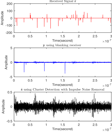
The received signal r, blanking output signal y (using the blanking method in [3, 16, 17, 19]), and the output of the proposed CDA algorithm for five frame time duration in multipath channel model CM1 [12] are shown in Fig. 1. The blanking non-linearity is applied to the received signal r. Samples of r are assigned zero value if , where is a constant threshold value. To mitigate impulse noise effect, threshold for the blanking based receiver in UWB system is selected such that false alarm and miss-detection probabilities are minimized. The optimal value of is derived as [3, 16, 17]
| (12) |
Similar to (in eq (6)) and (in eq (8)), and are calculated and expressed as and , respectively. The exact solution of (12) is difficult due to multiple functions. Hence, the function is approximated using a method in [20]. On equating the derivative of (12) to zero, a sub-optimal value of is obtained. For example, at an dB with , sub-optimal values of equal to 4 and 2.5 are obtained for SNR of -2 and 5 dB, respectively. In simulations, we have used fixed value of throughout the entire range of SNR. However, SNR specific can be selected using a look-up table method at the receiver, which requires frame based SNR estimation, thereby increasing computational complexity of the receiver.
In Fig. 1, we have considered dB, dB, blanking threshold (for blanking receiver), and impulse noise probability in this simulation setup. The amplitude of impulse noise samples is very high as observed in Fig. 1 (top subfigure) and the desired signal s is completely buried within the impulse noise. In the blanking based receiver [3, 16, 17], high amplitude samples of impulse noise are blanked (assigned zero value), while low amplitude impulse samples are present at the output of blanking unit in signal as shown in Fig. 1 (middle subfigure). Hence, performance of the blanking based receiver deteriorates due to the presence of few impulse noise samples and is sensitive to the threshold value . On the other hand, all the samples of impulse noise are removed with the proposed algorithm without any modification in the desired signal as observed in Fig. 1 (bottom subfigure).
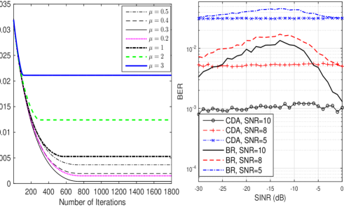
Further, the mean square error (MSE) between desired multipath received signal s and CDA output signal is calculated and defined as
| (13) |
where is the number of samples in s. In (13), signal s is fixed and CDA output signal changes after each iteration. Hence, MSE in (13) changes after each iteration. Simulation results are plotted in Fig. 2 (left) for dB and dB in multipath communication channel model CM1 using various values of the parameter in Algorithm 1. The rate of decrease in MSE with the number of iteration is same for all the values of . However, high values of saturate at higher error floor as compared to lower values () as observed from Fig. 2 (left). Further, provides the lowest value of error floor as shown in Fig. 2 (left). Based on empirical results, , where . Further, at a constant threshold value, BER performance of the blanking based receiver ([3, 16, 17]) varies with SINR as observed in Fig. 2 (right). On the other hand, the proposed receiver provides optimum results irrespective of the values of SINR chosen as observed in Fig. 2 (right). Further, BER performance of both the proposed and blanking receivers converge around dB due to low amplitude of impulse noise samples at these SINR values and hence, impulse noise behaves similar to Gaussian noise at dB.
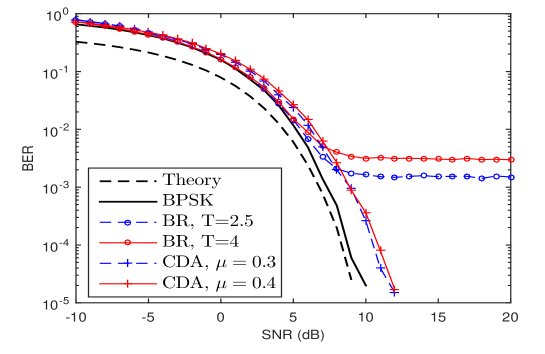
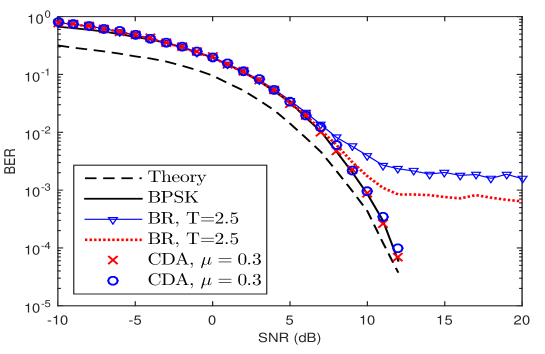
Next, the BER performance of TH-BPSK UWB system in the presence of impulse noise using the proposed receiver and the blanking non-linearity based receiver in [3, 16, 17] is analyzed in AWGN and multipath IEEE 802.15.4a channel CM1 [12]. Results are shown in Fig. 3 and Fig. 4. In AWGN channel, dB, , (for blanking receiver), and frame duration nanoseconds are chosen, while in CM1 channel, dB, , , and nanoseconds are considered. The blanking receiver exhibits bit error floor for both the values of threshold and SINR in the presence of impulse noise in both AWGN and CM1 channels as shown in Fig. 3 and and Fig. 4. The BER performance of the proposed receiver in the presence of impulse noise is close to the BER performance of the conventional receiver (BPSK) in impulse noise free scenario and is free from any bit error floor as observed in Fig. 3 and Fig. 4 respectively. Further, CDA based receiver’s BER performance is degraded marginally in AWGN channel due to non-zero (but small) unlike in the multipath channel, which has is close to zero. Proposed receiver needs around iterations per frame, hence it is computationally efficient and free from any SNR dependent threshold value selection like blanking receivers.
V Conclusion
A signal cluster sparsity based receiver design for the impulse noise mitigation in a UWB system is proposed. The proposed receiver is observed to be robust and has improved bit error rate performance (close to the impulse noise free system) as compared to the blanking non-linearity based receiver in the presence of Bernoulli-Gaussian impulse noise for single and multipath channels. The work presented in this paper is helpful for robust operation and analysis of UWB based devices such as WSNs, IoTs, and M2M that work extensively in harsh impulse noise environments and hence, require robust receiver designs in practical applications. In future, the proposed cluster sparsity based receiver design can be extended for multiuser communication in the presence of impulse noise environment.
References
- [1] H. Ding, W. Liu, X. Huang, and L. Zheng, “First path detection using rank test in IR UWB ranging with energy detection receiver under harsh environments,” IEEE Communications Letters, vol. 17, no. 4, pp. 761–764, 2013.
- [2] M. Cheffena, “Propagation channel characteristics of industrial wireless sensor networks [wireless corner],” IEEE Antennas and Propagation Magazine, vol. 58, no. 1, pp. 66–73, 2016.
- [3] S. V. Zhidkov, “Performance analysis and optimization of OFDM receiver with blanking nonlinearity in impulsive noise environment,” IEEE Transactions on Vehicular Technology, vol. 55, no. 1, pp. 234–242, 2006.
- [4] B. S. Kim, J. Bae, I. Song, S. Y. Kim, and H. Kwon, “A comparative analysis of optimum and suboptimum rake receivers in impulsive UWB environment,” IEEE Transactions on Vehicular Technology, vol. 55, no. 6, pp. 1797–1804, 2006.
- [5] N. Güney, H. Deliç, and M. Koca, “Robust detection of ultra-wideband signals in non-Gaussian noise,” IEEE Transactions on Microwave Theory and Techniques, vol. 54, no. 4, pp. 1724–1730, Apr. 2006.
- [6] J. Lin, M. Nassar, and B. L. Evans, “Impulsive noise mitigation in powerline communications using sparse Bayesian learning,” IEEE Journal on Selected Areas in Communications, vol. 31, no. 7, pp. 1172–1183, 2013.
- [7] H. El Ghannudi, L. Clavier, N. Azzaoui, F. Septier, and P.-A. Rolland, “-stable interference modeling and Cauchy receiver for an IR-UWB ad hoc network,” IEEE Transactions on Communications, vol. 58, no. 6, pp. 1748–1757, 2010.
- [8] S. Niranjayan and N. C. Beaulieu, “Novel adaptive nonlinear receivers for UWB multiple access communications,” IEEE Transactions on Wireless Communications, vol. 12, no. 5, pp. 2014–2023, 2013.
- [9] E. Ekrem, M. Koca, and H. Deliç, “Ultra-wideband signal acquisition in non-Gaussian noise via successive sampling,” in IEEE 65th Vehicular Technology Conference (VTC2007-Spring), 2007, pp. 1801–1805.
- [10] S. Sharma, V. Bhatia, and A. Gupta, “Sparsity based UWB receiver design in additive impulse noise channels,” in IEEE 17th International Workshop on Signal Processing Advances in Wireless Communications (SPAWC), 2016, pp. 1–5.
- [11] ——, “Sparsity-based narrowband interference mitigation in ultra wide-band communication for 5G and beyond,” Computers & Electrical Engineering, vol. 3, pp. 1–13, 2017.
- [12] A. F. Molisch, D. Cassioli, C.-C. Chong, S. Emami, A. Fort, B. Kannan, J. Karedal, J. Kunisch, H. G. Schantz, K. Siwiak et al., “A comprehensive standardized model for ultrawideband propagation channels,” IEEE Transactions on Antennas and Propagation, vol. 54, no. 11, pp. 3151–3166, 2006.
- [13] S. Sharma, V. Bhatia, and A. Gupta, “A non-coherent UWB receiver using signal cluster sparsity,” in IEEE 23rd National Conference on Communication (NCC), March 2017, pp. 1–6.
- [14] A. Yang, Z. Xu, H. Nie, and Z. Chen, “On the variance-based detection for impulse radio UWB systems,” IEEE Transactions on Wireless Communications, vol. 15, no. 12, pp. 8249–8259, 2016.
- [15] B. Silva and G. P. Hancke, “IR-UWB-based non-line-of-sight identification in harsh environments: Principles and challenges,” IEEE Transactions on Industrial Informatics, vol. 12, no. 3, pp. 1188–1195, 2016.
- [16] F. H. Juwono, Q. Guo, D. Huang, Y. Chen, L. Xu, and K. P. Wong, “On the performance of blanking nonlinearity in real-valued OFDM-based PLC,” IEEE Transactions on Smart Grid, vol. PP, no. 99, pp. 1–9, 2016.
- [17] U. Epple and M. Schnell, “Advanced blanking nonlinearity for mitigating impulsive interference in OFDM systems,” IEEE Transactions on Vehicular Technology, vol. 66, no. 1, pp. 146–158, 2017.
- [18] S. Sharma, A. Gupta, and V. Bhatia, “A new sparse signal-matched measurement matrix for compressive sensing in UWB communication,” IEEE Access, vol. 4, pp. 5327–5342, 2016.
- [19] K. M. Rabie and E. Alsusa, “Preprocessing-based impulsive noise reduction for power-line communications,” IEEE Transactions on Power Delivery, vol. 29, no. 4, pp. 1648–1658, 2014.
- [20] G. K. Karagiannidis and A. S. Lioumpas, “An improved approximation for the Gaussian Q-function,” IEEE Communications Letters, vol. 11, no. 8, pp. 644–646, 2007.