Breaking time-reversal symmetry with acoustic pumping of nanophotonic circuits
Abstract
Achieving non-reciprocal light propagation via stimuli that break time-reversal symmetry, without magneto-optics, remains a major challenge for integrated nanophotonic devices. Recently, optomechanical microsystems in which light and vibrational modes are coupled through ponderomotive forces, have demonstrated strong non-reciprocal effects through a variety of techniques, but always using optical pumping. None of these approaches have demonstrated bandwidth exceeding that of the mechanical system, and all of them require optical power, which are both fundamental and practical issues. Here we resolve both of these challenges through breaking of time-reversal symmetry using an acoustic pump in an integrated nanophotonic circuit. GHz-bandwidth optomechanical non-reciprocity is demonstrated using the action of a 2-dimensional surface acoustic wave pump, that simultaneously provides non-zero overlap integral for light-sound interaction and also satisfies the necessary phase-matching. We use this technique to produce a simple frequency shifting isolator (i.e. a non-reciprocal modulator) by means of indirect interband scattering. We demonstrate mode conversion asymmetry up to 15 dB, efficiency as high as 17%, over bandwidth exceeding 1 GHz.
Non-reciprocal devices, in which time reversal symmetry is broken for light propagation, provide critical functionalities for signal routing and source protection in photonic systems. The most commonly encountered non-reciprocal devices are isolators and circulators, which can be implemented using a variety of techniques encompassing magneto-optics [1, 2], parity-time symmetry breaking [3], spin-polarized atom-photon interactions [4, 5], and optomechanical interactions [6, 7, 8, 9, 10, 11, 12]. On the other hand, recent developments reveal a much broader and compelling vision of using time-reversal symmetry breaking for imparting protection against defects, through analogues of the quantum Hall effect [13] in both topological [14, 15, 16] and non-topological systems [17].
The use of optomechanical coupling [18] for breaking time-reversal symmetry via momentum biasing [19, 12] and synthetic magnetism [10, 11] is particularly attractive since strong dispersive features can be readily produced, without needing materials with gain or magneto-optical activity. Additionally, the potential for complete isolation with ultralow loss [7] is a significant advantage over state-of-the-art in chip scale magneto-optics. All these systems feature dynamic reconfigurability through the pump laser fields and can potentially be implemented in foundries with minimal process modification. Unfortunately, all realizations of optomechanical non-reciprocal interactions to date only operate over kHz-MHz bandwidth. This fundamental constraint arises simply because the interaction is determined by the mechanical linewidth, which is traditionally 6-9 orders of magnitude lower than the optical system (potentially several THz). In this work we present a new approach for optomechanical non-reciprocity where the bandwidth of the effect is no longer determined by the mechanics, but is instead determined by the photonic modes. We achieve this by inverting the roles of the mechanical and optical modes in a common optomechanical configuration so that acoustic pumping, as opposed to optical pumping, is used to break time-reversal symmetry. The practical implications of this new pumping strategy are transformative; we no longer need any additional lasers to drive the system, and more importantly, the linearity of the non-reciprocal effect is no longer limited to small optical signals. For the first time, an integrated nanophotonic device is produced that exhibits broken time-reversal symmetry over GHz bandwidth using a phonon pump.
The specific device that we implement for this demonstration is a non-reciprocal nanophotonic modulator. Light entering the device from one direction is transferred to a different optical band through phonon-mediated momentum shift and energy shift, i.e. indirect interband scattering [20, 21, 22]. Light entering from the opposite direction is simply resonantly dissipated. As such, the presented device operates as a frequency shifting optical isolator exhibiting 15 dB of contrast and up to 17% mode conversion efficiency. Unlike sophisticated electro-optic implementation of this idea [23], acoustic phonons naturally provide large momentum shifts at practical driving frequencies. Thus, it is unnecessary to slow down the effective phase velocity of the pumping signal to achieve indirect interband scattering using a phononic pump. The acoustic method also circumvents free carrier absorption that otherwise generates large losses in electro-optic waveguides.
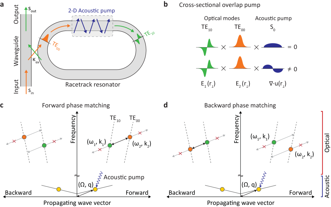
To explain this approach qualitatively, we consider an optomechanically-active racetrack resonator [24, 25] supporting quasi-TE10 () and quasi-TE00 () as visualized in Fig. 1. For convenience we drop the ’quasi-’ prefix. Indirect intermodal scattering [22] can be enabled between the optical modes as a result of the photoelastic perturbations of the medium by the driven acoustic wave () [21, 20]. While this optically resonant structure sacrifices the bandwidth over which acousto-optical interactions can occur, it provides giant opto-acoustic gain that is necessary to obtain appreciable light-vibration coupling within a small form factor [26]. The requisite phase matching conditions are illustrated in space in Fig. 1c,d. Under normal conditions, the TE00 momentum is higher than that of the TE10 mode (i.e. ).
We first consider the case illustrated in Fig. 1c where the resonance frequency of the TE00 racetrack mode is higher than that of the TE10 mode (). Here, a carefully designed acoustic transducer that generates phonons () between the modes can help satisfy the phase matching condition (, ) for acousto-optical scattering for forward propagating optical signals. For light propagating in the opposite direction, the momentum difference between the optical modes is now () which is not satisfied by the driven phonons. Thus the system exhibits broken time-reversal symmetry, i.e. intermodal scattering is permitted only for forward signals while the backward signals see no such effect. We can now also consider the case shown in Fig. 1d where the resonance frequency relation is opposite. In this case the phase-matching of scattering between the optical modes requires phonons having () in the forward direction and () in the backward direction. Thus, forward propagating phonons can only phase-match backward propagating optical modes in this case.
In addition to the above phase matching requirement, the acoustic wave must also assist with breaking orthogonality. When both optical modes are of TE polarization, the intermodal optomechanical coupling coefficient () is proportional to the cross-sectional overlap integral of the optical modes , and the acoustic mode displacement given by [27]:
| (1) |
As shown in Fig. 1b, the electric fields of TE10 and TE00 modes have odd and even shapes in the transverse direction, respectively. Therefore, the density variation associated with the acoustic wave must be asymmetric with respect to the center of the waveguide to ensure non-zero . In the case where the node is located exactly at the center of the waveguide, we can maximize the intermodal coupling and simultaneously suppress intramodal scattering by balancing out compressive and tensile strain in the waveguide.
The acousto-optic interaction in the forward phase matched case (Fig. 1c) can now be described using the coupled equations of motion for the optical fields (backward phase matched case in Supplement §S3):
| (2) |
where () is the intracavity field, () is the loaded decay rate of the TE10 (TE00) mode, is the phonon-enhanced optomechanical coupling rate, and is displacement associated with the acoustic pump. Here we assume that an input field at carrier frequency is provided to the resonator via an evanescently coupled waveguide (Fig. 1a) with coupling rates and to the TE10 and TE00 optical racetrack modes respectively. In the case where we probe the mode, we can express the optical susceptibility as where is Fourier frequency and is an additional optical loss rate induced by the acousto-optic interaction. In contrast, optically pumped optomechanical systems [6, 8, 9, 10, 11, 12, 17, 18, 19, 7] have an interaction term of the form where is the photon-enhanced optomechanical coupling rate, is decay rate of the mechanical mode, is the mechanical resonant frequency, and is the pump laser frequency [7]. We can immediately see that the interaction bandwidth in the acoustically pumped case is no longer defined by the linewidth of the mechanical mode, but instead by the linewidth of the optical mode. This feature enables an orders-of-magnitude higher bandwidth non-reciprocal interaction.
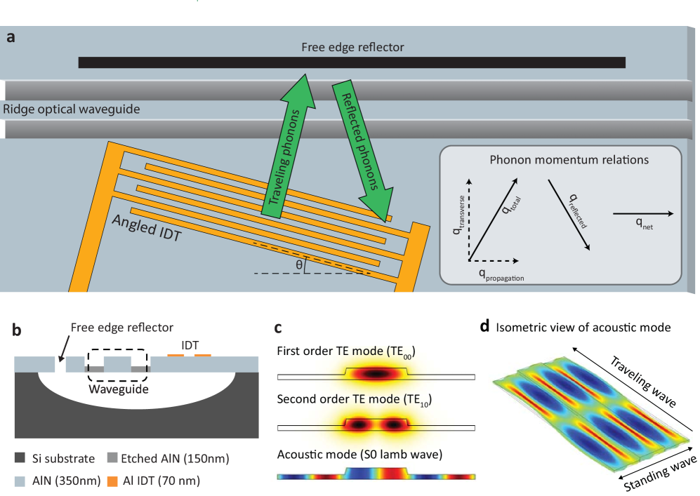
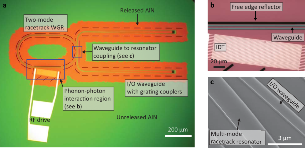
We fabricate the nonreciprocal modulator on an aluminum nitride (AlN) device layer on air platform, having an underlying a silicon handle wafer (Fig. 2a,b). This selection of materials ensures CMOS compatibility [28]. Here, the AlN supports the optical modes due to its high transparency in the telecom band [29, 28] and additionally functions as an excellent acoustic material on which phonons can be piezoelectrically driven (Fig. 2c,d) [30, 31, 32]. Details on the fabrication process are provided in Methods below. The device is composed of an AlN racetrack resonator that supports the required TE00 and TE10 modes around 1550 nm using a wrapped ridge waveguide (details provided in Supplement §S7). Other optical modes are suppressed by limiting the width (2.2 m) and thickness (350 nm) of the racetrack waveguide. The optical modes of the racetrack are accessed through an adjacent linear single-mode waveguide with a width of 800 nm that is coupled evanescently to the resonator at a single point. Grating couplers at the ends of the linear waveguide are used to provide optical access to the system. The as-fabricated waveguide geometries were evaluated using electron microscopy, which permitted more accurate refinement and finite-element simulation of the optical modes in Comsol Multiphysics. This procedure also allows us to evaluate the material refractive index as by matching against experimental measurement of the free spectral range (FSR) of each optical mode family within the resonator. The frequency difference between pairs of optical resonances varies due to the distinct dispersion of the TE00 and TE10 mode families (Fig. 4c).
The acoustic pump is provided to the resonator using an interdigitated transducer (IDT) that is fabricated on the same piezoelectric AlN substrate. The IDT pitch and angle are selected carefully in order to generate a 2-dimensional acoustic wave having the correct momentum in both propagating and transverse directions, as shown in Fig. 2a. In order to satisfy momentum conservation in the propagating direction, an acoustic propagation constant of is required. Since we simultaneously require a standing wave in the transverse direction, an acoustic free edge reflector is fabricated by cutting the AlN device layer through to the air below (Fig. 2a,b). This free edge reflector is placed at away from the waveguide in order to situate an acoustic node at the center of the waveguide and obtain an odd transverse profile (Fig. 1b). Based on simulation, the cross-sectional overlap integral is maximized when the transverse acoustic wavelength and the width of the optical wave guide are matched, setting transverse propagation constant to . Accounting for the transverse and propagating components of the acoustic wave, the total wave vector of the acoustic wave launched by the IDT is calculated as . The IDT angle is then set to , and pitch to = 546 nm. The required driving frequency of 4.82 GHz is calculated using finite element simulation of the S0 Lamb surface acoustic wave dispersion for the selected propagation constant. Fig. 2d presents a simulation of the 2-dimensional acoustic mode shape in the racetrack waveguide region. The intermodal modulation frequency and momentum can be tailored for different phononic and photonic modes by simply modifying the IDT parameters, without changing material phonon dispersion. Micrographs of the fabricated device are presented in Fig. 3.
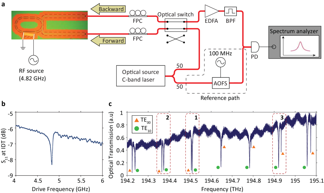
We experimentally demonstrate non-reciprocal modulation within the system by measuring the optical sidebands for both forward and backward probe signals, using the measurement setup shown in Fig. 4a (see also Methods). The primary acoustic component of the system, i.e. the IDT, is first characterized using s-parameter measurement (Fig. 4b) using a calibrated RF probe by means of an electronic vector network analyzer. The measured reflection coefficient (s11 parameter) shows a resonant dip corresponding to efficient conversion of the input electronic stimulus into the acoustic wave. We can directly measure this characteristic acoustic resonance at 4.82 GHz, corresponding to the S0 Lamb surface acoustic wave on the AlN substrate. In Fig.4c we present the measured optical transmission spectrum from the perspective of the coupling waveguide, where the transmission dips corresponding to the modes of the racetrack resonator are clearly visible. The TE00 mode is seen to have higher Q factor (Q 170,000) than the TE10 mode (Q 102,000). The measured free spectral ranges (FSR) of TE00 and TE10 resonances are respectively 140.5 GHz and 136 GHz near 194.7 THz optical frequency. Therefore, the inter-modal frequency difference changes by approximately 4.5 GHz for each consecutive mode pair. On the other hand, the momentum difference of each mode pair is the same since the azimuthal mode order of the pairs is the same.
Experimental measurements of the interband mode conversion are presented in Fig. 5. We consider three cases corresponding to mode pairs 1, 2, 3 as marked in Fig. 4c – which serve to illustrate both perfect and imperfect phase matching situations within the system. As mentioned above, these mode pairs all have identical separation in momentum-space. In this experiment, the RF frequency is fixed to 4.82 GHz where IDT can most efficiently actuate the acoustic wave. We sweep the optical probe across each pair of modes while measuring the power of transmitted carrier frequency component (), down-converted Stokes sideband (), and up-converted anti-Stokes sideband () (Fig. 5i, ii, iii) simultaneously. The measured power is normalized against the input power to the waveguide (). The RF drive power is set to 0 dBm so that the optical sidebands are small compared to the input light.
We first examine sideband generation and reciprocity in the case where both phase matching and the frequency matching are well satisfied (Fig. 5a). Here, the optical resonance frequency of the TE00 mode is lower than the resonance frequency of the TE10 optical mode by 4.55 GHz, implying that the phase matching condition is satisfied in the backward direction for a forward directed phonon pump (as illustrated in Fig. 1d). Measurements show (Fig. 5a,ii) that when each optical mode is probed in the backward direction, resonant sideband generation occurs with the assistance of the second optical mode. For laser detuning between 5-10 GHz (arbitrary reference) light from the waveguide primarily enters TE00 mode resulting in a strong anti-Stokes sideband. Scattering to Stokes is strongly suppressed (45 dB smaller than the anti-Stokes) since there is no optical mode available in the resonator. Similarly, for laser detuning between 10-15 GHz, light from the waveguide primarily enters the TE10 mode, and only the Stokes sideband is generated through resonant enhancement from the TE00 optical mode. Based on the fitting of the experimental data, we obtained a -3 dB bandwidth (full width half maximum) of 1.14 GHz for this modulation effect, which is determined by the optical resonance linewidths. We can also quantify the intermodal optomechanical coupling coefficient as GHz/nm (details in Supplement §S4).
On the other hand, when light enters the system in the forward direction where the momentum matching condition is not satisfied, very small light scattering is observed (Fig. 5a,iii). At the laser detuning where the maximum sideband amplitude is obtained in the backward direction, the sideband generated for forward probing is 15 dB smaller than that obtained for a backward laser probe. The measurement presented in Fig. 5a,iii is magnified by 10x in order for the data trends to be observable. The residual scattering that is observed has the characteristic functional shape of conventional intramodal modulation occurring from optical path length change. While this effect should nominally be zero, there are practical constraints associated with non-zero overlap integral due to acoustic-optical misalignment and the curvature of the racetrack.
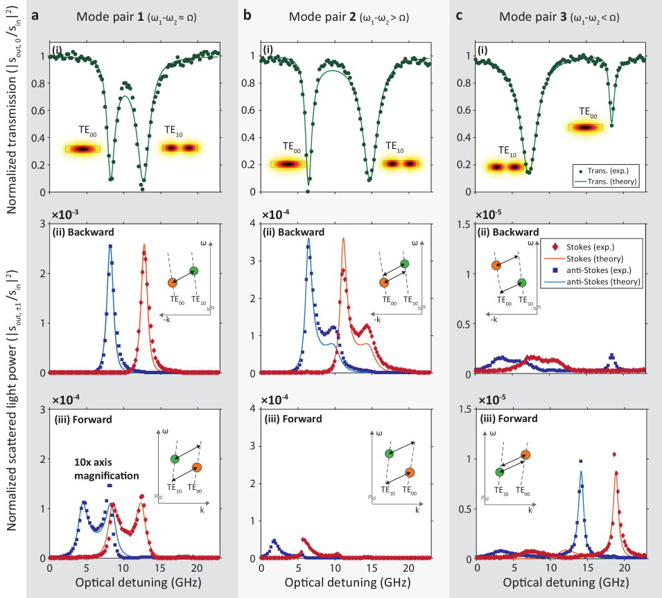
Next we examine the case of mode pair 2, where the optical modes have a larger (8.01 GHz) frequency separation but have identical momentum relationship (Fig. 5b). Here, the modes are frequency-mismatched with respect to the acoustic pump frequency, resulting in much lower indirect intermodal scattering. For a backward optical probe entering this system, we observe two Lorentzian shapes in both Stokes and anti-Stokes sideband data, corresponding to some intermodal conversion even though the phonon stimulus is non-resonant. The larger Lorentzian signature appears due to scattering from the peak of the TE00 resonance to off-resonance on the TE10 mode. Conversely, the smaller Lorentzian signature corresponds to scattering from an off-resonance point on the TE00 mode to the peak of the TE10 mode.
In the case of mode pair 3, opposite to mode pairs 1 and 2, the frequency of the TE00 mode is lower than the TE10 mode by 11.76 GHz. The phase matching in this case is thus only possible to satisfy in the opposite direction, i.e. for forward optical probing, corresponding to the situation shown in Fig. 1c. Measurements of light scattering for this mode pair (Fig. 5c) clearly show greater intermodal conversion for forward input light, even though the frequency matching for the modes is poor. Backward optical probing exhibits much smaller sidebands due to the momentum mismatch. All the above measurements clearly showcase how the 2-dimensional acoustic pump can be used to satisfy frequency and momentum phase-matching in either forward or backward directions, while also producing the necessary transverse overlap integral.
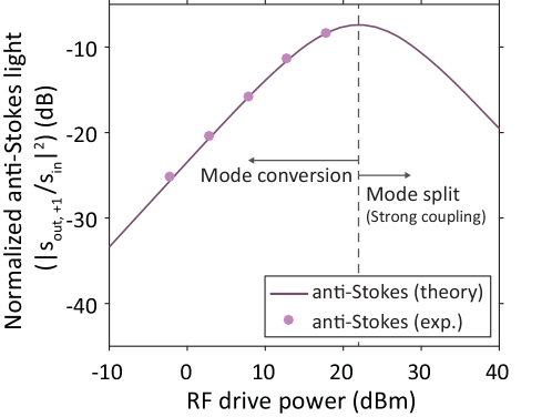
In order to test the maximum mode conversion efficiency available with strong acoustic pumping, we perform an experiment using the phase-matched mode pair 1 (Fig. 5a). The probe laser is applied in the backward, i.e. phase-matched, direction and is detuned from the TE00 resonance at the offset where the maximum anti-Stokes sideband is generated. The RF power stimulus to the IDT is then swept from -2.8 dBm to 17.8 dBm while the anti-Stokes sideband strength is measured (Fig. 6). The solid line in Fig. 6 is a theoretical curve produced using experimentally measured parameters (mode linewidths, coupling rates, optomechanical coupling coefficient) from fitting the data previously shown in Fig. 5a. At low drive power, when the sideband amplitude is much smaller than the carrier intracavity field, the mode conversion efficiency linearly increases with the pump. In our experiment, we were able to achieve a maximum of 17% sideband conversion efficiency on resonance when using 17.8 dBm RF input power. We calculate that the optomechanical coupling rate at this drive power is GHz. In a resonant structure, maximum sideband conversion is achievable at the equilibrium point where the amplitudes of the sideband and intracavity optical carrier field are matched (see Supplement §S3) since the rate of up and down conversion are then equal. Pumping beyond this point, i.e. , pushes the system into the strong coupling regime where the coupled optical modes begin to split (discussion in Supplement §S3). In this regime, for even stronger pumping, the sideband amplitude decreases while the optical carrier frequency component propagates nonreciprocally. In other words, the system begins to operate as a linear optical isolator. Unfortunately, due to IDT power limitations we were unable to reach the strong coupling regime in this experiment. However, partial verification of access to this regime is observable in Fig. 6 since the experimental results follow precisely the curvature of the predicted relationship. We again emphasize that the solid line in Fig. 6 is not a curve fit, but is a prediction of sideband field relative to the RF input. The conversion efficiency of this system could be improved tremendously by forming an acoustic waveguide (i.e. transverse acoustic resonator) by using free edge reflectors on both sides of the optical waveguide as demonstrated in [24].
The nanophotonic system that we have presented operates as a frequency shifting isolator in which light propagating in one direction experiences a fixed frequency offset, while in the opposite direction light is simply absorbed. This type of non-reciprocal device can play an important role in compact atomic timekeeping [33, 34], cold-atom inertial navigation [35], and gravimetry [36] in which magnet-induced Zeeman shifts and light shifts [37] are extremely undesirable. Moreover, the operational optical wavelength and pumping strategy of this system are entirely lithographically defined, which ensures rapid adaptability to other wavelength regimes. More broadly, this acoustic pumping technique and the level of performance achieved indicates a clear path towards foundry-compatible integration of linear isolators, circulators, and non-reciprocal phase shifters, that overcome the fundamental challenges currently plaguing state of the art non-magnetic non-reciprocal devices. This approach can also potentially introduce new non-reciprocal functionality to chip-scale photonics including frequency shifters [38] and dynamic converters for mode division multiplexing [39].
Methods
Device fabrication
We directly deposited c-axis oriented 350 nm film of aluminum nitride (AlN) by RF sputtering onto a silicon wafer. The AlN layer quality was confirmed through X-ray rocking curve measurement and stress measurement. The measured full width at half maximum from the rocking curve was 1.78 degree. The average stress of the AlN film was measured as -3.8 MPa (in compression). The devices were patterned through three electron-beam lithography steps. First, the AlN waveguide and racetrack resonator were patterned using e-beam lithography (Raith E-line) on ZEP-520 resist (ZEON corporation), followed by etching of 200 nm AlN using Cl2 based inductively coupled plasma reactive ion etching (ICP-RIE). Next, release holes and the acoustic edge reflector were patterned using e-beam lithography on double spin coated ZEP-520 resist, followed by complete etch back of the 350 nm AlN through ICP-RIE. Finally, the interdigitated transducers (IDTs) were patterned using e-beam lithography on PMMA photoresist after which 60 nm of Al was deposited using an e-beam evaporator. A subsequent lift-off process defines the aluminum IDTs. Finally, a gas-phase isotropic silicon etch was performed using XeF2 to release the device.
Mechanical transduction and electronic characterization
The IDT is used for exciting Lamb wave acoustic modes on the AlN piezoelectric substrate. RF signals are provided to the IDT via a ground-signal-ground (GSG) probe (Cascade Microtech model ACP 40). The transduction efficiency of the IDT was characterized using the standard approach using a vector network analyzer (Keysight model E5063A) through measurement of the reflection coefficient (s11). Details on this measurement are provided in the Supplement §S4. The vector network analyzer was calibrated using an on-chip impedance calibration standard to remove any effect of cables and the GSG probe.
Optical measurements
For performing measurements of intermodal light scattering, the experimental setup shown in Fig. 4a was used. An optical switch (Thorlab model OSW22-1310E) was used to control the light propagation direction, either forward or backward through the optical waveguide. We used a 1520-1570 nm tunable external cavity diode laser (New Focus model TLB-6728-P, 50 kHz instantaneous linewidth) to generate the optical probe. The laser source is split 50:50 into a device path and a reference path for performing heterodyne detection of the scattered light spectrum (details in Supplement §S2). Light in the device path was coupled to the on-chip waveguide through grating couplers. An erbium-doped fiber amplifier (EDFA) was used to amplify the light exiting the waveguide to facilitate detection. Light in the reference arm was provided a predetermined offset (100 MHz) using an in-fiber acousto-optic frequency shifter (AOFS, Brimrose model AMF-100-1550). The beat note between the reference light and the scattered light was measured by the high frequency photodetector (Newport model 1554 photoreceiver).
Acknowledgements
This material is based on research sponsored by Air Force Research Laboratory (AFRL) under agreement number FA9453-16-1-0025. The U.S. Government is authorized to reproduce and distribute reprints for Governmental purposes notwithstanding any copyright notation thereon. The views and conclusions contained herein are those of the authors and should not be interpreted as necessarily representing the official policies or endorsements, either expressed or implied, of Air Force Research Laboratory (AFRL) and (DARPA) or the U.S. Government.
References
- [1] D. Huang, P. Pintus, C. Zhang, P. Morton, Y. Shoji, T. Mizumoto, and J. E. Bowers, “Dynamically reconfigurable integrated optical circulators,” Optica, vol. 4, no. 1, pp. 23–30, 2017.
- [2] L. Bi, J. Hu, P. Jiang, D. H. Kim, G. F. Dionne, L. C. Kimerling, and C. A. Ross, “On-chip optical isolation in monolithically integrated non-reciprocal optical resonators,” Nature Photonics, vol. 5, no. 12, pp. 758–762, 2011.
- [3] B. Peng, S. K. Ozdemir, F. Lei, F. Monifi, M. Gianfreda, G. L. Long, S. Fan, F. Nori, C. M. Bender, and L. Yang, “Parity-time-symmetric whispering-gallery microcavities,” Nature Physics, vol. 10, no. 5, pp. 394–398, 2014.
- [4] C. Sayrin, C. Junge, R. Mitsch, B. Albrecht, D. O’Shea, P. Schneeweiss, J. Volz, and A. Rauschenbeutel, “Nanophotonic optical isolator controlled by the internal state of cold atoms,” Physical Review X, vol. 5, p. 041036, Dec 2015.
- [5] M. Scheucher, A. Hilico, E. Will, J. Volz, and A. Rauschenbeutel, “Quantum optical circulator controlled by a single chirally coupled atom,” Science, vol. 354, no. 6319, p. 1577, 2016.
- [6] M. S. Kang, A. Butsch, and P. S. J. Russell, “Reconfigurable light-driven opto-acoustic isolators in photonic crystal fibre,” Nature Photonics, vol. 5, no. 9, pp. 549–553, 2011.
- [7] J. Kim, S. Kim, and G. Bahl, “Complete linear optical isolation at the microscale with ultralow loss,” Scientific Reports, vol. 7, no. 1, p. 1647, 2017.
- [8] C. G. Poulton, R. Pant, A. Byrnes, S. Fan, M. J. Steel, and B. J. Eggleton, “Design for broadband on-chip isolator using stimulated brillouin scattering in dispersion-engineered chalcogenide waveguides,” Optics Express, vol. 20, no. 19, pp. 21 235–21 246, 2012.
- [9] Z. Shen, Y.-L. Zhang, Y. Chen, C.-L. Zou, Y.-F. Xiao, X.-B. Zou, F.-W. Sun, G.-C. Guo, and C.-H. Dong, “Experimental realization of optomechanically induced non-reciprocity,” Nature Photonics, vol. 10, no. 10, pp. 657–661, 2016.
- [10] K. Fang, J. Luo, A. Metelmann, M. H. Matheny, F. Marquardt, A. A. Clerk, and O. Painter, “Generalized non-reciprocity in an optomechanical circuit via synthetic magnetism and reservoir engineering,” Nature Physics, vol. 13, no. 5, pp. 465–471, 2017.
- [11] F. Ruesink, M.-A. Miri, A. Alu, and E. Verhagen, “Nonreciprocity and magnetic-free isolation based on optomechanical interactions,” Nature Communications, vol. 7, p. 13662, 2016.
- [12] C.-H. Dong, Z. Shen, C.-L. Zou, Y.-L. Zhang, W. Fu, and G.-C. Guo, “Brillouin-scattering-induced transparency and non-reciprocal light storage,” Nature Communications, vol. 6, 6193, 2015.
- [13] B. I. Halperin, “Quantized Hall conductance, current-carrying edge states, and the existence of extended states in a two-dimensional disordered potential,” Physical Review B, vol. 25, pp. 2185–2190, 1982.
- [14] Z. Wang, Y. Chong, J. D. Joannopoulos, and M. Soljacic, “Observation of unidirectional backscattering-immune topological electromagnetic states,” Nature, vol. 461, no. 7265, pp. 772–775, 2009.
- [15] M. Hafezi, S. Mittal, J. Fan, A. Migdall, and M. Taylor, J., “Imaging topological edge states in silicon photonics,” Nature Photonics, vol. 7, no. 12, pp. 1001–1005, 2013.
- [16] R. Susstrunk and S. D. Huber, “Observation of phononic helical edge states in a mechanical topological insulator,” Science, vol. 349, no. 6243, p. 47, 2015.
- [17] S. Kim, X. Xu, J. M. Taylor, and G. Bahl, “Dynamically induced robust phonon transport and chiral cooling in an optomechanical system,” arxiv.org, Jun 2017, arXiv:1609.08674.
- [18] M. Aspelmeyer, T. J. Kippenberg, and F. Marquardt, “Cavity optomechanics,” Reviews of Modern Physics, vol. 86, pp. 1391–1452, 2014.
- [19] J. Kim, M. C. Kuzyk, K. Han, H. Wang, and G. Bahl, “Non-reciprocal Brillouin scattering induced transparency,” Nature Physics, vol. 11, no. 3, pp. 275–280, 2015.
- [20] L. Kuhn, P. F. Heidrich, and E. G. Lean, “Optical guided wave mode conversion by an acoustic surface wave,” Applied Physics Letters, vol. 19, no. 10, pp. 428–430, 1971.
- [21] I. K. Hwang, S. H. Yun, and B. Y. Kim, “All-fiber-optic nonreciprocal modulator,” Optics Letters, vol. 22, no. 8, pp. 507–509, 1997.
- [22] Z. Yu and S. Fan, “Complete optical isolation created by indirect interband photonic transitions,” Nature Photonics, vol. 3, no. 2, pp. 91–94, 2009.
- [23] H. Lira, Z. Yu, S. Fan, and M. Lipson, “Electrically driven nonreciprocity induced by interband photonic transition on a silicon chip,” Physical Review Letters, vol. 109, p. 033901, 2012.
- [24] H. Shin, W. Qiu, R. Jarecki, J. A. Cox, R. H. Olsson III, A. Starbuck, Z. Wang, and P. T. Rakich, “Tailorable stimulated Brillouin scattering in nanoscale silicon waveguides,” Nature Communications, vol. 4, 1944, 2013.
- [25] E. A. Kittlaus, N. T. Otterstrom, and P. T. Rakich, “On-chip inter-modal Brillouin scattering,” arxiv.org, Nov 2016, arXiv:1611.03556.
- [26] N. Dostart, S. Kim, and G. Bahl, “Giant gain enhancement in surface-confined resonant stimulated Brillouin scattering,” Laser & Photonics Reviews, vol. 9, no. 6, pp. 689–705, 2015.
- [27] G. S. Agarwal and S. S. Jha, “Multimode phonon cooling via three-wave parametric interactions with optical fields,” Physical Review A, vol. 88, p. 013815, 2013.
- [28] C. Xiong, W. H. P. Pernice, and H. X. Tang, “Low-loss, silicon integrated, aluminum nitride photonic circuits and their use for electro-optic signal processing,” Nano Letters, vol. 12, no. 7, pp. 3562–3568, 2012.
- [29] C. Xiong, W. H. P. Pernice, X. Sun, C. Schuck, K. Y. Fong, and H. X. Tang, “Aluminum nitride as a new material for chip-scale optomechanics and nonlinear optics,” New Journal of Physics, vol. 14, no. 9, p. 095014, 2012.
- [30] S. A. Tadesse and M. Li, “Sub-optical wavelength acoustic wave modulation of integrated photonic resonators at microwave frequencies,” Nature Communications, vol. 5, 5402, 2014.
- [31] H. Li, S. A. Tadesse, Q. Liu, and M. Li, “Nanophotonic cavity optomechanics with propagating acoustic waves at frequencies up to 12 GHz,” Optica, vol. 2, no. 9, pp. 826–831, 2015.
- [32] G. Piazza, P. J. Stephanou, and A. P. Pisano, “Piezoelectric aluminum nitride vibrating contour-mode MEMS resonators,” Journal of Microelectromechanical Systems, vol. 15, no. 6, pp. 1406–1418, 2006.
- [33] S. Knappe, V. Shah, P. D. D. Schwindt, L. Hollberg, J. Kitching, L.-A. Liew, and J. Moreland, “A microfabricated atomic clock,” Applied Physics Letters, vol. 85, no. 9, pp. 1460–1462, 2004.
- [34] F.-X. Esnault, E. Blanshan, E. N. Ivanov, R. E. Scholten, J. Kitching, and E. A. Donley, “Cold-atom double- coherent population trapping clock,” Physical Review A, vol. 88, p. 042120, 2013.
- [35] T. L. Gustavson, P. Bouyer, and M. A. Kasevich, “Precision rotation measurements with an atom interferometer gyroscope,” Physical Review Letters, vol. 78, pp. 2046–2049, 1997.
- [36] A. Peters, K. Y. Chung, and S. Chu, “High-precision gravity measurements using atom interferometry,” Metrologia, vol. 38, no. 1, p. 25, 2001.
- [37] E. Blanshan, S. M. Rochester, E. A. Donley, and J. Kitching, “Light shifts in a pulsed cold-atom coherent-population-trapping clock,” Physical Review A, vol. 91, p. 041401, 2015.
- [38] L. Fan, C.-L. Zou, M. Poot, R. Cheng, X. Guo, X. Han, and H. X. Tang, “Integrated optomechanical single-photon frequency shifter,” Nature Photonics, vol. 10, no. 12, pp. 766–770, 2016.
- [39] L.-W. Luo, N. Ophir, C. P. Chen, L. H. Gabrielli, C. B. Poitras, K. Bergmen, and M. Lipson, “WDM-compatible mode-division multiplexing on a silicon chip,” Nature Communications, vol. 5, p. 3069, 2014.