Multi-Antenna Assisted Virtual Full-Duplex Relaying with Reliability-Aware Iterative Decoding
Abstract
In this paper, a multi-antenna assisted virtual full-duplex (FD) relaying with reliability-aware iterative decoding at destination node is proposed to improve system spectral efficiency and reliability. This scheme enables two half-duplex relay nodes, mimicked as FD relaying, to alternatively serve as transmitter and receiver to relay their decoded data signals regardless the decoding errors, meanwhile, cancel the inter-relay interference with QR-decomposition. Then, by deploying the reliability-aware iterative detection/decoding process, destination node can efficiently mitigate inter-frame interference and error propagation effect at the same time. Simulation results show that, without extra cost of time delay and signalling overhead, our proposed scheme outperforms the conventional selective decode-and-forward (S-DF) relaying schemes, such as cyclic redundancy check based S-DF relaying and threshold based S-DF relaying, by up to 8 dB in terms of bit-error-rate.
I Introduction
Next generation wireless communication networks are expected to rely on low latency and high spectral efficiency cooperative relaying nodes [1]. This is due to their capability to serve as a virtual multi-antenna system to combat fading and be able to extend communication coverage[2, 3, 4]. However, conventional cooperative relaying networks limit relay nodes on half-duplex (HD) mode, where the HD relay nodes can either receive or transmit data symbols at a given time-instant. With such kind of design, the cooperative system can avoid inter-frame interference and exploit spatial diversity gain. On the other hand, it suffers from spectral efficiency loss since transmission of one data frame needs to occupy two independent time slots or frequency bands.
Recent research works in [5, 6, 7] show that full-duplex (FD) relaying becomes feasible for simultaneous transmission and reception when advanced self-interference cancellation methods can be exploited [8, 9]. However, in practical environments, self-interference cannot be completely cancelled due to inaccurate self-interference channel modeling and/or limited dynamic range of analog-to-digital converter[10]. Consequently, the residual self-interference increases burden on decoding process at the FD relay node and results in error propagation. In [11, 12, 13], a promising technique named virtual FD relaying (or two-path successive relaying) has been proposed, where two HD relay nodes mimic a FD relay node and alternately serve as transmitter and receiver to continuously transmit data frames for every channel use. This scheme benefits from simplified curcit designs, and the optimal performance can be achieved if both HD relay nodes are able to perfectly cancel the inter-relay interference and decode their received messages[14, 15]. Otherwise, error propagation effects degrade system performances.
In order to avoid error propagation effects, the authors in [12, 14, 16, 17, 18] presented adaptive retransmission based relaying schemes to guarantee perfect decoding at relay nodes. However, this scheme has additional costs of time delay and signalling overhead [19, 20, 21, 22]. Alternatively, the authors in [23, 24, 25] proposed symbol-level selective transmission schemes, where relay nodes can predict their correctly decoded symbols based on the pre-determined threshold and discard the the erroneously decoded symbols, resulting in fewer errors being forwarded to destination node. However, in order to guarantee the quality of decoding process at destination, the relay nodes need to forward the position of their discarded symbols to destination node, where the additional signalling overhead still exists. On the other hand, imperfect inter-relay interference cancellation may reduce the decoding capability at relay nodes [26, 27, 28]. With the help of multiple receive-antenna, the detection techniques, such as zero-forcing (ZF) or minimum mean square error (MMSE), can be implemented to suppress the inter-relay interference. However, the majority drawback of ZF is noise power boost, and MMSE needs to know noise variance information.
Motivated by the above discussion, in this paper, we propose a multi-antenna assisted virtual FD relaying with reliability-aware iterative decoding at destination node in order to improve system spectral efficiency and reliability. Specifically, relay nodes first ultilize QR decodposition method to perfectly cancel the inter-relay interference and then forward their decoded data frames regardless the decoding errors. Subsequently, destination node performs the reliability-aware iterative detection/decoding method by taking the estimated probability of decoding error at relay nodes (e.g. ) into account. In the literature, multi-antenna assisted iterative decoding was proposed in [29] for point-to-point communication network and in [30] for network coding aided two-way relaying network. Comparison with the works in [29, 30], our proposed scheme is for virtual FD relaying network and the additional challenge is how to jointly cancel inter-frame interference and enjoy spatial diversity gain at destination node. In addition, we also introduce an estimation method of for the iterative decoding process. Simulation results show that, without extra cost of time delay and signalling overhead , our proposed scheme exhibits up to 8 dB bit-error-rate (BER) performance gain by comparing with conventional cyclic redundancy check (CRC) based S-DF relaying and threshold based S-DF relaying schemes.
II System Model
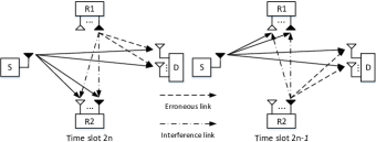
Fig. 1 illustrates the multi-antenna assisted virtual FD relaying network with one single-antenna based source node (S), two -antenna based HD relay nodes (R1/R2) and one -antenna based destination node (D).
All transmissions are using single antenna and all receptions are using antennas.111In order to keep consistent with the source node, two relay nodes transmit data frames with single antenna. The multi-antenna based transmission at relay nodes can be easily extended to enjoy additional antenna gain. We also assume discrete-time block fading channels, which remain static over each time slot. All reception nodes can estimate and have their related channel state information. The source node first encodes the information bits using the turbo-like encoders, e.g., -rate serial concatenated convolutional codes, to generate the coded bits . Then, are mapped into transmission symbols based on -ary modulation scheme. Subsequently, are divided into frames, and without loss of generality is assumed to be even.
As shown in Fig. 1, the source node continuously transmits the frame in the time slot, where . In the first time slot, only relay node one (R1) and destination node receive the first data frame from source node. Starting from the second time slot, two relay nodes alternatively transmit and receive data frames until the time slot. Then, in the time slot, only relay node two (R2) forwards its last decoded frame (i.e. the ) to destination node. Let and be the received signal matrices at the , relay and the destination node in the time slot, respectively, where is the number of symbols per frame. Then, we have
| (1) |
| (2) |
where is the transmitted signal matrix in the time slot composed by the frame sent from the , relay, i.e., , and the frame sent from the source node, i.e., ; is transpose of a matrix; is the channel matrix which consists of the R-R link and S-R link in the time slot; is the channel matrix which consists of R-D link and S-D link in the time slot; and are the additive white Gaussian noise (AWGN) matrices at the relay and the destination nodes in the time slot, respectively. It is worth noting that, in the first time slot, since relay node one receives data frame sent from the source node without inter-relay interference effect, the transmitted signal in this case should be , where is a column vector with all zeros. Similarly, in the time slot, since only relay node two (R2) sends data frame to destination node, the transmitted signal in this case should be . Apart from that, in this paper, relay nodes decodes its received frame and then forwards its re-encoded version regardless of decoding errors, then the destination node will based on our proposed method to mitigate the error propagation effect.
III The Proposed Scheme for Interference and Error Propagation Mitigation
According to the system model described above, there are three main factors that affect the system performances, which are the inter-relay interference generated at relay nodes, the inter-frame interference generated at destination node, and the error propagation effect due to decoding errors at relay nodes. In this section, we mainly introduce how to cancel and limit these impacts with our proposed methods.
III-A Inter-relay Interference Cancellation at Relay Nodes
Due to alternative transmission and reception between two relay nodes, the presented inter-relay interference should be cancelled before they can decode the received data frames. In this case, by introducing QR decomposition, the inter-relay interference at relay nodes can be perfectly cancelled without boosting noise power. Specifically, we take the relay node as an example and assume is the unitary matrix and is the upper triangular matrix, where both matrices are generated from QR decomposition of the channel matrix . Then, the received signal at the relay node, after multiplying the unitary matrix , can be expressed as
| (5) | |||||
where is hermitian of a matrix. Due to the upper triangular structure of , the desired signal sent from the source node without inter-relay interference effects is the second row of matrix . In addition, due to the nice feature of , the multiplication of by does not change the power of AWGN matrix. Thus, based on the above description, the relay node can decode the second row of in order to regenerate data frame sent from source node, i.e., . Then, it will be forwarded to destination node in the time slot.
III-B Reliability-Aware Iterative Decoding at Destination Node
In this paper, we allow relay nodes forward their received signals regardless decoding error. In this case, error propagation could degrade the system performance. In addition, due to simultaneously receiving signals sent from source and one of relay nodes, the inter-frame interference at destination node also affects system performance. In this subsection, we introduce a reliability-aware iterative detection/decoding method to mitigate the above effects.
It is shown in the literature that MAP based detection technique has been widely used to cancel inter-frame interference. However, in order to allow the MAP detector have the capacity to jointly cancel inter-frame interference and remove the error propagation effects, we need to modify its detection process. Specifically, we start from transforming (2) to the real-valued equivalent form. Such transformation allows the proposed method suit for different modulation schemes, e.g., generalized -ary modulation schemes. Let’s assume that , , and are the real matrices transformed from , , and , respectively, where we have
| (6) |
| (7) |
| (8) |
Additionally, let denote the real-valued channel matrix transformed from , as
| (11) |
Then, the real-valued equivalent form of (2) can be expressed as
| (12) |
According to the work in [29], the conventional MAP detector is to solve the optimization problem, which is
| (13) |
where and are the columns of and , respectively;222It is worth noting that in (13) are the corresponding trial bits vector used in this hypothesis-detection problem. is the a posteriori probability for , where is the component of the symbol vector . As each constellation symbol represents modulated bits (e.g., for a -ary constellation), we assume are the modulated bits for the symbol vector .333Two times of represents two symbols included in , where one is from the source node, and one is from the relay node. Since the output of the MAP detector requires the soft information for the next step decoding process, the LLR of the modulated bit for the symbol vector can be expressed as
| (14) |
where has been defined in (13); is the short-hand used to denote the symbol vector ; represent logical 0 with amplitude level +1, and represent logical 1 with amplitude level -1.
Different from the conventional MAP detector presented above, our proposed MAP detector needs to be aware of the error propagation effects. Specifically, we first define as the probability of decoding error at one of relay nodes in the time slot. This probability can be estimated during the iterative decoding at destination node. More detailed analysis of its estimation method will be introduced in Section III-C. Based on the transformed , in (7), all the components from the odd rows of represent the symbol sent from one of relay nodes, and all the components from the even rows of represent the symbol sent from the source node. Let’s define a modulated bits set representing all the components from the odd rows of , and is its complementary set representing all the components from the even rows of . By taking into account, the a posteriori probabilities of the modulated bits sent from the relay node can be modified as
where denotes the modified probability of the bit sent from the relay node and . Then, by replacing with in (III-B) when , the LLR value of the , , modulated bits sent from the source node can be expressed as
| (15) |
where
| (16) |
On the other hand, due to the error prorogation effects, the LLR value of the , , modulated bits sent from the relay node can be expressed as (III-B), shown on the top of next page,
where
| (18) |
Here, we omit the detailed derivation of (III-B) because of the limited space. On the other hand, the basic principle of deriving (III-B) is to solve on the condition that for the numerator of (III-B) and on the condition that for the denominator of (III-B). Similar analisis method for the network coding aided two-way relaying system can be found in [30].
Fig. 2 illustrates the iterative detection/decoding process at destination node.
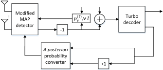
With the obtained LLR values from (15) and (III-B), the modified MAP detector now is able to separate the data frames sent from the relay and the source nodes, meanwhile, the error propagation effect can be eliminated by taking into account. Here, destination node needs to wait all frames being detected by the modified MAP detector before the iterative process started. Then, it will add up two versions of LLR values per frame, e.g., the frame sent from the relay node in the time slot and the frame sent from the source node in the time slot, for the turbo-like decoder. The LLR values of the coded bits per frame, after the turbo decoder, will then be duplicated and fed into the a posteriori probability converter to generate the a posteriori probabilities for the next iteration. In the a posteriori probability converter, the a posteriori probabilities are found from the LLR values using the modulator mapping function. In addition, in Fig. 2, the blocks “-1” denote backward-shifting the frame number, “+1” denote forward-shifting the frame number, and denote the error probability parameter estimation.
III-C Error Probability Parameter Estimation
As discussed in Section III-B, in order to mitigate the error propagation effect, the probabilities of decoding error at relay nodes should be taken into account in the iterative decoding process. These probabilities can be estimated at relay nodes and then be forwarded to destination node at the cost of signalling overhead. On the other hand, they can be directly estimated at destination node, where the estimation method will be introduced in this subsection.
As shown in Fig. 2, the error probability estimation process should be carried out in each of detection/decoding iterations. In detail, let’s define is the number of modulated bits per each constellation symbol sent from either source node or one of relay nodes. Then, the estimated probabilities can be given by
| (19) |
where are the probabilities for the bits sent from the source node; are the probabilities for the bits sent from the relay node. Then, (III-C) can be further transformed to
where represents the LLR value of the modulated bit sent from the source node, which is derived from (15); represents the LLR value of the modulated bit sent from one of relay node, which is derived from (III-B). After the error probabilities for all frames being estimated in each iteration, they will be fed back and used by the modified MAP detector in the next iteration. It is worth noting that the accuracy of the estimated probabilities can be improved with the iteration number.
III-D Computational Complexity of Iterative Decoding
Based on the above analysis, the proposed iterative decoding process can be summarized as
| Reliability-Aware Iterative Decoding | |
|---|---|
| I. Initialize A posteriori probabilities and set ; | |
| II. While : | |
| Increasing by 1; | |
| Calculate LLRs for all frames based on (15) | |
| and (III-B); | |
| Estimate based on (III-C); | |
| Combine two version of LLR values per frame | |
| and then send them to turbo decoder; | |
| Send the LLRs of coded bits to A posteriori | |
| probability converter; | |
| Feed back the output of A posteriori probabili- | |
| -ties to modified MAP detector; | |
| III. End While |
where is the number of outer iterations. The computational complexity mainly comes from Step II-2 and Step II-4. Specifically, for Step II-2, modified MAP detector is implemented and its complexity mainly depends on the number of receive antenna and modulation size; for Step II-4, the complexity of standard turbo-like decoder should be taken into account. For the rest steps, like Step II-3 and Step II-5, the complexity just involves certain element-wise multiplication and additions, which can be ignored by comparing with Step II-2 and Step II-4.
IV Simulation Results
Computer simulations are used to evaluate the BER performances of our proposed multi-antenna assisted virtual FD relaying with reliability-aware iterative decoding method. We assume all channels are generated as independent block Rayleigh fading, which remain static over each transmission time slot. For transmitting, source and relay nodes are using one transmit antennas, and for receiving, relay and destination nodes are with receive antennas. In addition, there are frames being transmitted via time slots, and each frame consists of information bits. SNR denotes the transmission signal power normalized by noise power ratio. The quadrature phase-shift keying (QPSK) modulation and turbo-like channel coding are implemented, e.g., 1/2 rate serial concatenated convolutional code for both source and relay nodes, where the first encoder is the non-recursive non-systematic convolutional code with a generator polynomial , and the second encoder is the doped-accumulator with a doping rate equalling two. Random interleavers are implemented, and the results are computed on an average over 1000 independent channel realizations.
Four baselines are used for comparisons: 1) Perfect decoding at relay nodes: this is served as performance bound, where we assume both relay nodes can correctly decode their received messages all the time and the same iterative decoding at destination node as our proposed scheme; 2) Proposed iterative decoding (ID) without : relay nodes always forward their decoded symbols regardless decoding errors and the iterative decoding at destination node does not take into account; 3) CRC based S-DF: relay nodes only forward if their received messages can be correctly decoded and the same iterative decoding at destination node as our proposed scheme; 4) Threshold based S-DF: relay nodes only forwards if their decoded errors are less than 15% and the same iterative decoding at destination node as our proposed scheme. In addition, the QR-decomposition based detection method at relay nodes is implemented for all the schemes.
Fig.3 shows BER performances for different schemes with relay-location A.
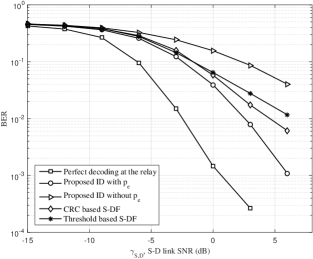
Let’s define as the distance between the and nodes, and . Thus, we have for the relay-location A. As a consequence, based on a simplified suburban area pathloss model with the pathloss exponent equalling to 3.52, SNR relationship in dB among different links can be approximated by . As shown in Fig.3, Perfect decoding at relay nodes scheme undoubtedly gives the best BER performance. Proposed ID with scheme gives the second best BER performance due to the iterative decoding process at destination node by taking the error propagation effects into account. In contrast, Proposed ID without scheme gives the worst BER performance. The BER performances of two S-DF based schemes are in the middle between Proposed ID with scheme and Proposed ID without scheme. This is because the S-DF based schemes prefer to remain silent rather than propagate decoding errors if the number of decoding errors above their limits.
Fig.4 gives BER performances for different schemes with a different relay location (e.g. relay-location B).
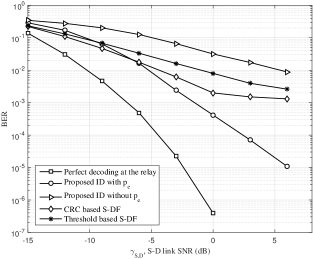
In this case, given , we have and . Then, similar as relay-location A, the corresponding SNR relationship in dB among different links can be approximated by and . Such location is the case that relay nodes are close to source node. As shown in Fig.4, the same BER performance trend as Fig.3 is presented, where Proposed ID with scheme gives the second best BER performance. In comparison with Fig.3, the BER performance gap between Proposed ID with scheme and the conventional S-DF based schemes in Fig.4 is larger than the ones in Fig.3, where the performance gap in Fig.4 exhibits up to 8 dB gain. This is because, with relay-location B, the decoding capability of relay nodes increases due to high S-R link quality. On the other hand, for the conventional S-DF based schemes, one or a few bits decoding errors will stop them forwarding their received frames to enjoy the spatial diversity gain. This is also why there is error floor for CRC based S-DF scheme.
V Conclusion
In this paper, a multi-antenna assisted virtual FD relaying with reliability-aware iterative decoding has been proposed. Based on QR decomposition, our proposed scheme can cancel the inter-relay interference without boosting noise power at relay nodes. In addition, our proposed scheme allows two relay nodes forward the erroneously decoded symbols and jointly cancels inter-frame interference and error propagation effect at destination node. It has been shown that, without extra cost of time delay and signalling overhead, our proposed scheme exhibits up to 8 dB gain by comparing with the conventional S-DF based schemes especially when relay nodes are close to source node.
Acknowledgement
This work was supported by the Engineering and Physical Science Research Council (EPSRC) through the Scalable Full Duplex Dense Wireless Networks (SENSE) grant EP/P003486/1.
References
- [1] I. Orikumhi, C. Y. Leow, and Z. Ding, “Wireless information and power transfer in MIMO virtual full-duplex relaying system,” IEEE Trans. Veh. Technol., pp. 1–10, 2017.
- [2] J. N. Laneman, D. N. C. Tse, and G. W. Wornell, “Cooperative diversity in wireless networks: Efficient protocols and outage behavior,” IEEE Trans. Inf. Theory, vol. 50, no. 12, pp. 3062–3080, Dec. 2004.
- [3] K. Azarian, H. E. Gamal, and P. Schniter, “On the achievable diversity-multiplexing tradeoff in half-duplex cooperative channels,” IEEE Trans. Inf. Theory, vol. 51, no. 12, pp. 4152–4172, Dec. 2005.
- [4] A. Shadmand and M. Shikh-Bahaei, “Multi-user time-frequency downlink scheduling and resource allocation for LTE cellular systems,” in Proc. IEEE Wireless Commun. and Networking Conf., Apr. 2010, pp. 1–6.
- [5] A. Sabharwal, P. Schniter, D. Guo, D. W. Bliss, S. Rangarajan, and R. Wichman, “In-band full-duplex wireless: Challenges and opportunities,” IEEE J. Sel. Areas Commun., vol. 32, no. 9, pp. 1637–1652, Sept. 2014.
- [6] G. Liu, F. R. Yu, H. Ji, V. C. M. Leung, and X. Li, “In-band full-duplex relaying: A survey, research issues and challenges,” IEEE Commun. Surv. Tutor., vol. 17, no. 2, pp. 500–524, 2015.
- [7] M. Naslcheraghi, S. A. Ghorashi, and M. Shikh-Bahaei, “FD device-to-device communication for wireless video distribution,” IET Commun., vol. 11, no. 7, pp. 1074–1081, May 2017.
- [8] S. Hong, J. Brand, J. Choi, M. Jain, J. Mehlman, S. Katti, and P. Levis, “Applications of self-interference cancellation in 5g and beyond,” IEEE Commun. Mag., vol. 52, pp. 114–121, Feb. 2014.
- [9] E. Ahmed and A. M. Eltawil, “All-digital self-interference cancellation technique for full-duplex systems,” IEEE Trans. Wireless Commun., vol. 14, no. 7, pp. 3519–3532, Feb. 2015.
- [10] D. Kim, H. Lee, and D. Hong, “A survey of in-band full-duplex transmission: From the perspective of phy and mac layers,” IEEE Commun. Surv. Tutor., vol. 17, no. 4, pp. 2017–2046, 2015.
- [11] T. J. Oechtering and A. Sezgin, “A new cooperative transmission scheme using the space-time delay code,” in Proc. ITG Wksp. Smart Antennas, Mar. 2004, pp. 41–48.
- [12] Y. Fan, C. Wang, J. S. Thompson, and H. V. Poor, “Recovering multmultiple loss through successive relaying using repetition coding,” IEEE Trans. Wireless Commun., vol. 6, no. 12, pp. 4484–4493, Dec. 2007.
- [13] F. Lehmann, “A factor graph approach to iterative channel estimation, detection, and decoding for two-path successive relay networks,” IEEE Trans. Wireless Commun., vol. 15, no. 8, pp. 5414–5429, Aug. 2016.
- [14] H. Wicaksana, S. H. Ting, Y. L. Guan, and X.-G. Xia, “Decode-and-forward two-path half-duplex relaying: Diversity-multiplexing tradeoff analysis,” IEEE Trans. Commun., vol. 59, no. 7, pp. 1985–1994, Jul. 2011.
- [15] J. Fan, L. Li, H. Zhang, and W. Chen, “Denoise-and-forward two-path successive relaying with dbpsk modulation,” IEEE Wireless Commun. Lett., vol. 6, no. 1, pp. 42–45, Feb. 2017.
- [16] H. Bobarshad and M. Shikh-Bahaei, “M/m/1 queuing model for adaptive cross-layer error protection in wlans,” in Proc. IEEE Wireless Commun. and Networking Conf., Apr. 2009, pp. 1–6.
- [17] L. Zhang, W. Liu, A. Quddus, M. Dianati, and R. Tafazolli, “Adaptive distributed beamforming for relay networks based on local channel state information,” IEEE Trans. Signal Process., vol. 1, no. 2, pp. 117–128, Jun. 2015.
- [18] E. E. B. Olivo, D. P. M. Osorio, H. Alves, G. C. S. S. Filho, and S. Latva-aho, “An adaptive transmission scheme for cognitive decode-and-forward relaying networks: Half duplex, full duplex, or no cooperation,” IEEE Trans. Wireless Commun., vol. 15, no. 8, pp. 5586–5602, Aug. 2016.
- [19] M. Shikh-Bahaei, M. Mouna-Kingue, and G. C. Nokia, “Joint optimisation of outer-loop power control and rate adaptation over fading channels,” in Proc. IEEE Veh. Tech. Conf.., Sept. 2004, pp. 2205–2209.
- [20] A. Olfat and M. Shikh-Bahaei, “Optimum power and rate adaptation with imperfect channel estimation for mqam in rayleigh flat fading channel,” in Proc. IEEE Veh. Tech. Conf., Sept. 2005, pp. 2468–2471.
- [21] A. Kobravi and M. Shikh-Bahaei, “Cross-layer adaptive arq and modulation tradeoffs,” in Proc. IEEE Int. Symp. Personal, Indoor and Mobile Radio Communications, Sept. 2007, pp. 1–5.
- [22] A. Shadmand and M. Shikh-Bahaei, “TCP dynamics and adaptive MAC retry-limit aware link-layer adaptation over ieee 802.11 wlan,” in Proc. Seventh Annual Commun. Networks and Services Research Conf., May 2009, pp. 193–200.
- [23] G. Al-Habian, A. Ghrayeb, M. Hasna, and A. Abu-Dayya, “Threshold-based relaying in coded cooperative networks,” IEEE Trans. Veh. Technol., vol. 60, pp. 123–135, Jan. 2011.
- [24] T. Kwon, S. Lim, S. Choi, and D. Hong, “Optimal duplex mode for df relay in terms of the outage probability,” IEEE Trans. Veh. Technol., vol. 59, no. 7, pp. 3628–3633, Sept. 2010.
- [25] N. Yi, Y. Ma, J. Hou, and R. Tafazolli, “Symbol-level selective decode-forward relaying for uncoordinated dense wireless networks,” in Proc. IEEE Int. Wksp. Computer Aided Modelling and Design of Communication Links and Networks, Sept. 2015, pp. 283–287.
- [26] L. Sun, T. Zhang, and H. Niu, “Inter-relay interference in two-path digital relaying systems: Detrimental or beneficial?” IEEE Trans. Wireless Commun., vol. 10, no. 8, pp. 2468–2473, Aug. 2011.
- [27] E. Basar, U. Aygolu, E. Panayirci, and H. V. Poor, “A reliable successive relaying protocol,” IEEE Trans. Commun., vol. 62, no. 5, pp. 1431–1443, May 2014.
- [28] F. Zarringhalam, B. Seyfe, M. Shikh-Bahaei, G. Charbit, and H. Aghvami, “Jointly optimized rate and outer loop power control with single- and multi-user detection,” IEEE Trans. Wireless Commun., vol. 8, no. 1, pp. 186–195, Jan. 2009.
- [29] H. Vikalo, B. Hassibi, and T. Kailath, “Iterative decoding for MIMO channels via modified sphere decoding,” IEEE Trans. Wireless Commun., vol. 3, no. 6, pp. 2299–2311, Nov. 2004.
- [30] K. Lee and L. Hanzo, “MIMO-Assisted hard versus soft decoding-and-forwarding for network coding aided relaying systems,” IEEE Trans. Wireless Commun., vol. 8, no. 1, pp. 376–385, Jan. 2009.