Reorientational solitons in nematic liquid crystals with modulated alignment
Abstract
In uniaxial soft matter with a reorientational nonlinearity, such as nematic liquid crystals, a light beam in the extraordinary polarization walks off its wavevector due to birefringence, while it undergoes self-focusing via an increase in refractive index and eventually forms a spatial soliton. Hereby the trajectory evolution of solitons in nematic liquid crystals— nematicons— in the presence of a linearly varying transverse orientation of the optic axis is analysed. In this study we use and compare two approaches: i) a slowly varying (adiabatic) approximation based on momentum conservation of the soliton in a Hamiltonian sense; ii) the Frank-Oseen elastic theory coupled with a fully vectorial and nonlinear beam propagation method. The models provide comparable results in such a non-homogeneously oriented uniaxial medium and predict curved soliton paths with either monotonic or non-monotonic curvatures. The minimal power needed to excite a solitary wave via reorientation remains essentially the same in both uniform and modulated cases.
pacs:
42.65.Tg, 42.70.Df, 05.45.YvThis paper is dedicated to one of its coauthors, Professor Antonmaria (Tim) A. Minzoni, who prematurely passed away during its preparation. N.F.S. and G.A. remember Tim as a generous person of vast culture, a dear friend and an outstanding colleague.
I Introduction
Nematic liquid crystals (NLCs) are anisotropic, typically uniaxial, soft matter with several peculiar properties. As suggested by the name, derived from the Greek, they consist of thread-like molecules and exhibit orientational but no spatial order khoo . The anisotropic molecules are in a fluid state, linked by elastic forces, and exhibit two refractive index eigenvalues, ordinary and extraordinary, for light polarized perpendicular or parallel to the optic axis, termed the molecular director and usually denoted by the unit vector . The refractive index of extraordinary polarized light has a nonlinear optical dependence through the reorientational response: the electric field of the light beam induces dipoles in the NLC molecules, so that they tend to rotate towards the field vector to minimize the system energy until the elastic response balances this electromechanical torque khoo . The resulting change in molecular orientation then changes the extraordinary refractive index towards the largest eigenvalue, so that the beam undergoes self-focusing. When self-focusing compensates linear diffraction, a solitary wave can form, often termed a nematicon PR ; Wiley ; karpierz6 . Nematicons are non-diffracting solitary beams in nematic liquid crystals, confined by their own graded-index waveguides. They have been extensively investigated over a number of years in many different scenarios, such as planar cells Peccianti:2000 ; Henninot:2002 ; Beeckman:2004 ; Assanto:2007 ; peccianti2008_mol_reorientation ; Alberucci:2010_2 ; Alberucci_JOSAB ; Izdebskaya:2010 ; Kwasny2012 , capillaries Warenghem_solitons1998 ; Warenghem:1998 , waveguides karpierz2002_physrevE ; smyth2002 and bulk ISI:000393991400001 . When the wavevector of the light beam and the molecular director are neither perpendicular nor parallel, the Poynting vector of the nematicon walks-off the wavevector at a finite angle owing to the tensorial nature of the dielectric susceptibility walk . Such an angular deviation of the energy flux depends on the refractive index eigenvalues, and for electric fields parallel and perpendicular to the director, respectively, and the angle between the director and wavevector. Nematicon walk-off can be exploited in optical devices, for instance, signal demultiplexers or routers Piccardi:2010 ; Piccardi:2010_2 ; Piccardi:2010_4 ; Piccardi:2010_5 ; Barboza:2011 ; Piccardi:2012_2 ; sala_jnopm2014 .
In uniform NLCs, nematicons propagate along rectilinear trajectories along their Pointing vector. The corresponding graded index waveguides associated with these spatial solitons are therefore straight. Curved light induced waveguides have been investigated in NLCs by means of graded interfaces NPhys:2006 ; peccianti2008_mol_reorientation ; Piccardi:2008 ; Barboza:2011 ; Piccardi:2012_2 , localized refractive index perturbations Pasquazi:2005 ; refract ; Piccardi:2010_2 , interactions with boundaries Alberucci:2007_2 ; Alberucci_JOSAB ; Izdebskaya:2010_2 as well as other nematicons Henninot:2002 ; Peccianti:2002_1 ; Fratalocchi:2007 ; Izdebskaya:2010 ; Jisha:2011 . At variance with previous approaches, in this article we introduce and study curved reorientational spatial solitons as they propagate in nematic liquid crystals with a linearly varying orientation of the optic axis across the transverse coordinate in the principal plane (defined by director and wavevector). We consider nematicons excited in a planar cell of fixed (uniform) thickness, with upper and lower interfaces treated to ensure planar anchoring of the NLC molecules. This geometry is radically different from those entailing spin-orbit interactions of light with matter Slussarenko:2016 ; Alberucci:2016 ; Alberucci:2017 , as the optic axis and the wavevector are not mutually orthogonal since the light beam is an extraordinary wave . As the molecular alignment varies across the sample, both the extraordinary refractive index and the birefringent walk-off vary as well. These two variations determine the resulting trajectory of extraordinarily polarized beams in the cell, including the path of self-confined nematicons. To investigate nematicon paths in a transversely modulated uniaxial we use two different approaches in the weakly nonlinear regime (i.e. power independent walk-off): (i) numerical solutions of the full governing Maxwell’s equations employing a fully vectorial beam propagation method for the beam and the Frank-Oseen elastic theory for the NLC response PR ; (ii) an adiabatic (slowly varying) approximation to yield simplified forms of these equations, invoking momentum conservation PR ; largeamp . The adiabatic approximation is based on the high nonlocality of the NLCs, which implies that the nonlinear response extends far beyond the transverse size of the optical wavepacket PR ; conti2 ; JNOPM2016 and decouples the amplitude/width evolution of the beam from its trajectory ben ; bennonlocal . In this study the background director angle is slowly varying, typically / in a cell of width , so that the nematicon trajectory can be determined by “momentum conservation”, in the sense of invariances of the Lagrangian for the NLC equations. The latter approach yields simple equations which have an exact solution and provides excellent agreement with the full numerical solutions, proving more than adequate to model beam evolution in non-uniform birefringent media.
II Geometry and governing equations
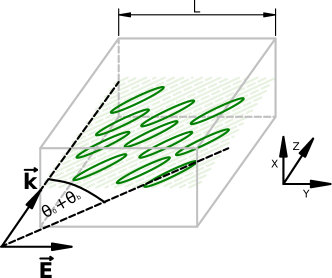
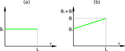
We consider the propagation of a linearly polarized, coherent light beam in a cell filled with an undoped positive uniaxial nematic liquid crystal. The extraordinary polarized beam is taken to initially propagate forward in the direction, with electric field oscillating in the transverse direction and completing the coordinate triad. To eliminate the Freédericksz threshold khoo and maximize the nonlinear optical response Peccianti:2005 , the cell interfaces perpendicular to are rubbed so that the molecular director makes an angle with in the plane everywhere in the bulk owing to elastic interactions, as sketched in Fig. 1. An additional -dependent rotation is given to the nematic director to modulate the uniaxial medium, as illustrated in Fig. 2(b). Due to the nonlinearity, the light beam can rotate the optic axis by an extra angle , so that the director forms a total angle to the axis in the plane Peccianti:2004 ; Peccianti:2005 .
II.1 Beam propagation method and elastic theory
One of the approaches used to study the nonlinear evolution of a light beam in nematic liquid crystals is the fully vectorial beam propagation method (FVBPM) ziogos2008 in conjunction with elastic theory based on the Frank-Oseen model for the NLC response khoo ; frank ; oseen . The FVBPM can be derived directly from Maxwell’s equations sala2012_mclc ; sala_mclc2012_Discrete_Diffraction , considering harmonically oscillating electric and magnetic fields in an anisotropic dielectric
| (1) | |||||
Here the complex amplitudes and are the electric and magnetic fields, respectively, is the electric permittivity tensor, is the angular frequency and is the vacuum permeability. These coupled partial differential equations can be solved numerically, as the and derivatives can be approximated using standard central differences and the solution can be propagated forward along using a standard fourth-order Runge-Kutta scheme. In this work the step size is chosen to be . At the cell boundaries, reflective Dirichlet boundary conditions are imposed, so that and at the NLC/glass interfaces. The electric tensor in equations (1) is
| (5) |
with the optical anisotropy. These electromagnetic equations are coupled to the NLC response, given by the Frank-Oseen expression for the energy density in the non-chiral case khoo ; frank ; oseen
| (6) | |||||
Here, are the Frank elastic constants for bend, twist and splay deformations of the molecular director , respectively PR . The equation for the NLC elastic response is obtained by taking variations of this free energy. However, doing so results in a large system of equations sala_OptExpress2012 . To overcome this complexity, we note that in the examined configuration the molecular director and the electric field of the beam lie in the same (principal) plane ; hence, as nonlinear reorientation occurs in this same plane and the azimuthal components can be neglected, the director can be expressed in polar coordinates . Since the changes in molecular orientation along are slow as compared with the wavelength of light, the derivatives with respect to can also be neglected. In this approximation, the variations of the free energy (6) yield the Euler-Lagrange equation
| (7) |
leading to the director rotation in the form
| (8) |
Numerical solutions of this elliptic equation (8) are found using successive over-relaxations (SOR) with relaxation parameter SOR_book . When combined with the numerical solution of the electromagnetic model (1), solutions for beam propagation in nematic liquid crystals with varying orientation can be obtained. The director reorientation is recalculated after each nm of propagation; after the first step in , the solution for is the initial guess for the SOR iterations, ensuring rapid convergence. The accuracy of the method described above can be estimated from the ratio of total input and output powers, which should be unity because absorption is neglected and the boundary conditions are purely reflective. Defining the relative error as , we aim to achieve for all the cases considered here. In this work, the typical cell dimensions (thickness width length) are and two simple anchoring conditions are analyzed, uniform and linearly varying, see Fig. 2. For the sake of a realistic analysis, we choose the material parameters corresponding to the standard nematic liquid crystal 6CHBT, with Frank elastic constants , and and indices and at temperature T= and wavelength walk ; crc . The input beam is Gaussian and -polarized, with a full width half maximum and power .
II.2 Momentum conservation
The full system (1) and (8) governing the propagation of a light beam in a non-uniform NLC cell is extensive and amenable to numerical solutions only. However, these equations can be simplified to yield a reduced system for which an adiabatic approximation applies based on the slow variation of the director orientation. This adiabatic approximation shows that the beam trajectory is determined by an overall “momentum conservation” (MC) equation. This is not physical momentum, but momentum in the sense of the invariances of the Lagrangian in the reduced system. Such reduction of the full system and the resulting momentum conservation equation will now be derived.
The first approximation is that the imposed linear modulation in the director orientation is much smaller than the constant background , . For the examples considered here, typical values are and maximum ranging from to . While the largest is not strictly much smaller than , nevertheless the asymptotic results are found to be in good agreement with the numerical ones even at this upper limit. As discussed in the previous section, we denote the additional nonlinear reorientation by , so that the total pointwise orientation is . In the paraxial, slowly varying envelope approximation, the equations (1) and (8) governing the propagation of the light beam through the NLC can be reduced to conti2 ; PR ; Wiley
| (9) | |||
| (10) |
As for the full equations of Section II.1, is the complex valued envelope of the electric field of the beam, since in the paraxial approximation the components and are neglected. The Laplacian is in the transverse plane. In the single constant approximation, the parameter is a scalar on the assumption that bend, splay and twist in the full director equation (8) have comparable strengths. The wavenumber of the input light beam is intended in vacuum and is the background extraordinary refractive index of the NLC PR ; Wiley
| (11) |
in the linear limit . The coefficient is related to the birefringent walk-off angle of the extraordinary-wave beam, with in the plane, and is given by
| (12) |
Throughout this work, despite the nonlinear dependence of on the beam power through the reorientation Peccianti:2005_2 ; Piccardi:2010 ; Piccardi:2010_4 , we assume in the low power limit. In the single elastic constant approximation, the director equations (8) and (10) differ by a factor of in the dipole term involving , owing to definitions of the electric field based on either the maximum amplitude or the RMS (Root Mean Square) value. In this context, this difference is equivalent to a rescaling of , with the latter constant cancelling out in the adiabatic momentum conservation approximation.
The reduced equations (9) and (10) can be set in non-dimensional form via the variable and coordinate transformations
| (13) |
where
| (14) |
for a Gaussian input beam power of and wavelength waveguide . With these non-dimensional variables, Eqs. (9) and (10) become
| (15) | |||||
| (16) |
In deriving these equations we assumed that the NLC director rotation from is small, i.e., , as discussed above. We further assumed that the nonlinear response is small, with . The trigonometric functions in the dimensional equations (9) and (10) have been expanded in Taylor series largeamp . The scaled parameters in these non-dimensional equations are
| (17) |
The equations (15) and (16) have the Lagrangian formulation
| (18) | |||||
where the ∗ superscript denotes the complex conjugate. Equations (15) and (16) have no general exact solitary wave, or nematicon, solution; the only known exact solutions are for specific, related values of the parameters mike . For this reason, variational and conservation law methods have proved to be useful to study nematicon evolution mike ; tim , as they give solutions in good agreement with numerical and experimental results waveguide ; mike ; tim ; wenjun . In particular, they provide accurate results for the refraction of nematicons due to variations in the dielectric constant wenjun ; refract ; wenjunrefract ; scatter ; wenjunvortex . Conservation laws based on the Lagrangian (18) are used below to determine the nematicon trajectory in a cell with an imposed linear modulation of the orientation angle .
The easiest way to obtain the approximate momentum conservation equations for Eqs. (15) and (16) is from the Lagrangian (18) bennonlocal ; ben . We assume the general functional forms
| (19) |
where
| (20) |
for the nematicon and the director responses, respectively bennonlocal ; ben . The actual beam profile is not specified, as the trajectory is found to be independent of this functional form ben . In response to the change in the NLC refractive index, the extraordinary wave beam undergoes refraction, as well as amplitude and width oscillations. If the length scale of the refractive index change is larger than the beam width, the beam refraction decouples from the amplitude/width oscillations refract ; scatter ; bennonlocal . Consistent with this decoupling, the electric field amplitude and the width of the beam, the amplitude and width of the director response can be taken as constant if just the beam trajectory is required. Only the beam center position and (transverse) “velocity” are then taken to depend on , as well as the phase . This approximation is equivalent to momentum conservation for the Lagrangian (18) newell .
Substituting the profile forms (19) into the Lagrangian (18) and averaging by integrating in and from to whitham gives the averaged Lagrangian tim
| (21) | |||||
where primes denote differentiation with respect to . Here and , which determine the beam trajectory, are expressed by
| (22) | |||||
| (23) |
The integrals , and and appearing in this averaged Lagrangian are
| (24) | |||
Taking variations of this averaged Lagrangian with respect to and yields the modulation equations
| (25) | |||||
| (26) |
which determine the beam trajectory. Eq. (25) is the momentum equation.
A simple reduction of the trajectory Eqs. (25) and (26) can be carried out when the beam width is much less than the length scale for the variation of the refractive index, that is the length scale of the variation of ben . For the examples in this work, . Hence, a length scale for the variation of is , while the typical beam width is . The linear variation of the angle from the background angle starts at at . Since the beam is launched at the mid-section of the cell , where the total angle in the absence of light is , it is more accurate to expand the walk-off in a Taylor series about rather than . If we set , the integrals (22) and (23) can be approximated by
| (27) | |||||
We note that has been further approximated by expanding in a Taylor series about on taking , discussed above. With this simplification, the trajectory equations (25) and (26) become
| (28) | |||||
| (29) |
The simplicity of the beam trajectory equations (28) and (29) enables exact solutions for simple angle modulations . The simplest is the linear case
| (30) |
sketched in Fig. 2(b). For this linear case, goes from at to at . This variation of enables the momentum equations (28) and (29) to be solved exactly and give the position of the beam center as
| (31) | |||||
as is a constant. We assumed that the beam is launched at with at .
Since is slowly varying, the trajectory solution given by Eq. (31) can be expanded in a Taylor series to yield
| (32) | |||||
The first term in square brackets is the trajectory in a uniform NLC and the terms in the second set of square brackets are the correction due to a changing orientation. For the examples hereby, and . So, to first order in small quantities
| (33) |
as is small. Hence, the trajectory is described by the term for a uniform medium and a quadratic correction; the walk-off change due to the varying background director orientation dominates the change in the nematicon trajectory.
To convert the non-dimensional solution (31) back to dimensional variables, the scalings (14) are used. In particular, for the scaling factor , the angle for the extraordinary index (11) needs to be calculated. The obvious choice is to use the uniform background angle . However, while this leads to good agreement with the numerical solutions, near exact agreement is obtained by using the total director angle in the absence of light. The imposed component is not constant, but a slowly varying (linear) function of , as discussed above, so its local value can be used to transform back to dimensional variables, consistent with a multiple scales analysis cole . This local variation in the scaling factor for gives a metric change in this coordinate, with a small, slowly varying alteration of the trajectory. Nevertheless, the overall effect of this small local change is significant over propagation distances of and larger.
III Results and discussion
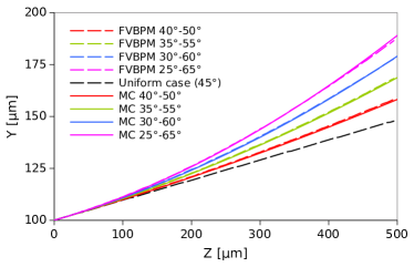
Figure 3 shows a comparison of nematicon trajectories in the modulated NLC as given by the adiabatic momentum approximation (31) and by the FVBPM solution of the full system (1) and (8). The considered cell has a range of linear variations in the background director angle of the form (30). Each individual case, , is indicated in the figure. A Gaussian beam is launched at the center of the cell, with its trajectory becoming curved due to the non-uniform director alignment. In a uniform medium the (straight) nematicon trajectory is determined solely by the walk-off, which leads to a rectilinear path in the plane. For the modulated uniaxial medium, not only the walk-off changes due to the varying anchoring, but the phasefront of the wavepacket is also distorted as the dielectric properties are modified and the NLC behaves like a lens with an index distribution given by (11). Clearly, the momentum conservation approximation gives trajectories in close agreement with the numerical results. This validates the approximations made to arrive at the momentum conservation equations (28) and (29), in particular the assumption that the beam trajectory is not influenced by its amplitude-width oscillations. Furthermore, it shows how powerful such adiabatic approximations can be. Nonetheless, the momentum result is a kinematic approximation and so does not give all the information for the evolving beam, whereas the full system (1) and (8) can also provide the amplitude-width evolution. A final point regarding Figure 3 is that if the background angle for the extraordinary refractive index (11) in the scaling (14) was chosen as rather than , there would have been a noticeable difference between the momentum conservation and numerical results. The local variation of the propagation metric due to the modulated director angle in the absence of light, in fact, has a significant effect on beam propagation.
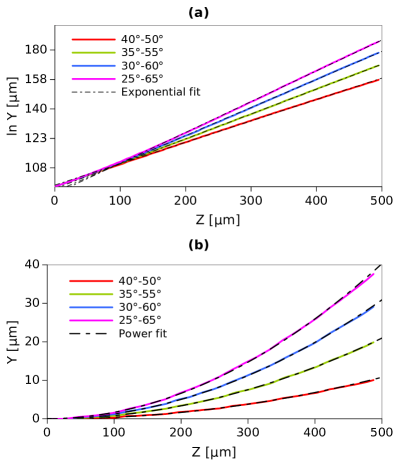
These results are further analyzed in Fig. 4(a). The data is plotted to a logarithmic scale with an exponential regression fitted through the numerical trajectories. As increases the trajectories are well approximated by an exponential evolution, in agreement with the momentum conservation solution (31) as for large the decaying exponential is negligible and the growing exponential dominates. Furthermore, when the rectilinear nematicon path in a uniform NLC is subtracted from the trajectory in the modulated case, the resulting beam position has a quadratic evolution in , as shown in Fig. 4 (b). These exponential and quadratic fittings of the trajectories are consistent with and being small, as demonstrated by reducing the full trajectory (31) to the quadratic approximation (33) via (32).
For a positive change of the anchoring conditions, i.e. , walk-off and phase distortion both increase the beam deviation. In the opposite case for which these two phenomena counteract. The influence of walk-off and phase change on the nematicon path was analyzed for the case of the director orientation changing by , as shown in Fig. 5. When the beam bends strongly due to both the walk-off and phase distortions acting in the same direction, as illustrated in Fig. 5 (a). The phase change is strongest at the launch position as the molecules are oriented at approximately there, so walk-off (given by (12) with ) is close to its maximum. All the trajectories are monotonic and the beam transverse deviation increases with propagation distance. As for the comparisons in Figure 3, the agreement between the momentum conservation and numerical trajectories is near perfect, except for the lowest angle variation from to , for which the agreement is still satisfactory. In the latter case the initial director angle at the input is far from the walk-off maximum at , so the trajectory bending is weak. Small errors in the momentum approximation then become relevant.
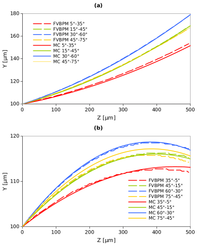
In the opposite case the walk-off and the phase change along the cell counteract, resulting in the solitary beam reversing its transverse velocity, as illustrated in the comparison of Fig. 5 (b). The agreement between the momentum conservation and numerical trajectories is nearly perfect, except for two noticeable cases. The first is for the modulation from to , opposite to what noted in the previous paragraph. The reason for the disagreement is again the weak bending of the beam and the enhanced role of small errors in the momentum approximation. The other case is the to modulation. It can be seen from Fig. 5 (b) that as the range of varies the beam reaches a maximum deviation in . The to variation is just after this turning point. As for the to case, small errors in the momentum conservation approximation can then result in large trajectory deviations, in particular errors in the changes required for the maximum displacement in .
Finally, we note that comparable beam powers are needed to obtain nematicons in uniform and linearly modulated NLCs, as a input beam is sufficient to excite them in both cases, i.e. the rate of change in anchoring does not significantly modify the threshold power for reorientational solitons.
IV Conclusions
We have studied the optical propagation of reorientational spatial solitons in nematic liquid crystals encompassing a transverse modulation of their optic axis (director) orientation. Even in the simplest limit of a linear change in anchoring angle, as considered here, non-uniform walk-off and wavefront distortion determine a bending of the resulting nematicon trajectory, leading to curved paths and curved optical waveguides induced by light through reorientation. Based on comparisons with numerical solutions obtained by FVBPM and elastic theory for self-localized light beam propagation in non-uniform nematic liquid crystals, we found that “momentum conservation” is an excellent approximation for modelling soliton paths in highly nonlocal media. It provides simple results for these trajectories and a highly intuitive explanation for their evolution, at variance with the highly coupled form of the full governing equations. While full numerical solutions can well describe nematicon evolution under generic conditions, the simplicity of the momentum conservation theory and its analytical solution speak in its favour for specific limits within the adiabatic category. Due to the slow variation of the anchoring conditions, both models show that the nematicon trajectory can be described as propagation in a uniform medium with a quadratic correction. Additionally, the power needed to excite reorientational solitons in either uniform or linearly non-uniform NLCs is comparable. Further studies will investigate the role of longitudinal director modulations, as well as combinations of transverse and longitudinal changes, unveiling scenarios for the design of arbitrary nematicon paths and corresponding all-optical waveguides.
Acknowledgements
F. A. Sala thanks the Faculty of Physics, Warsaw University of Technology, for a grant. U. A. L. thanks the National Centre for Research and Development in Poland under the grant agreement LIDER/018/309/L-5/13/NCBR/2014. G. Assanto thanks the Academy of Finland for support through the Finland Distinguished Professor grant no. 282858.
References
- (1) I.-C. Khoo, Liquid Crystals: Physical Properties and Nonlinear Optical Phenomena, Wiley, New York (1995).
- (2) M. Peccianti and G. Assanto, “Nematicons,” Phys. Rep., 516, 147–208 (2012).
- (3) G. Assanto, Nematicons, Spatial Optical Solitons in Nematic Liquid Crystals, John Wiley and Sons, New York (2012).
- (4) G. Assanto and M. A. Karpierz, “Nematicons: self-localised beams in nematic liquid crystals,” Liq. Cryst., 36, 1161–1172 (2009).
- (5) M. Peccianti, G. Assanto, A. De Luca, C. Umeton and I. C. Khoo, “Electrically assisted self-confinement and waveguiding in planar nematic liquid crystal cells,” Appl. Phys. Lett., 77, 7–9 (2000).
- (6) J.F. Henninot, M. Debailleul and M. Warenghem, “Tunable non-locality of thermal non-linearity in dye doped nematic liquid crystal,” Mol. Cryst. Liq. Cryst., 375, 631–640 (2002).
- (7) J. Beeckman, K. Neyts, X. Hutsebaut, C. Cambournac and M. Haelterman, “Simulations and experiments on self-focusing conditions in nematic liquid-crystal planar cells,” Opt. Express, 12, 1011–1018 (2004).
- (8) G. Assanto, A. Fratalocchi and M. Peccianti, “Spatial solitons in nematic liquid crystals: from bulk to discrete,” Opt. Express, 15, 5248–5259 (2007).
- (9) M. Peccianti, A. Dyadyusha, M. Kaczmarek and G. Assanto, “Escaping solitons from a trapping potential,” Phys. Rev. Lett., 101, 153902 (2008).
- (10) A. Alberucci, A. Piccardi, M. Peccianti, M. Kaczmarek and G. Assanto, “Propagation of spatial optical solitons in a dielectric with adjustable nonlinearity,” Phys. Rev. A, 82, 023806 (2010).
- (11) A. Alberucci and G. Assanto, “Propagation of optical spatial solitons in finite-size media: interplay between nonlocality and boundary conditions,” J. Opt. Soc. Amer. B, 24, 2314–2320 (2007).
- (12) Y. V. Izdebskaya, V. G. Shvedov, A. S. Desyatnikov, W. Z. Krolikowski. M. Belic, Ga. Assanto and Y. S. Kivshar, “Counterpropagating nematicons in bias-free liquid crystals,” Opt. Express, 18, 3258–3263 (2010).
- (13) M. Kwasny, U.A. Laudyn, F.A. Sala, A. Alberucci, M.A. Karpierz and G. Assanto, “Self-guided beams in low-birefringence nematic liquid crystals,” Phys. Rev. A, 86, 013824 (2012).
- (14) M. Warenghem. J. Henninot and G. Abbate, “Non-linearly induced self waveguiding structure in dye doped nematic liquid crystals confined in capillaries,” Opt. Express, 2, 483–490 (1998).
- (15) M. Warenghem, J.F. Henninot and G. Abbate, “Bulk optical Freedericksz effect: non-linear optics of nematics liquid crystals in capillaries,” Mole. Crys. Liq. Cryst., 320, 207–230 (1998).
- (16) M.A. Karpierz, “Solitary waves in liquid crystalline waveguides,” Phys. Rev. E, 66, 036603 (2002).
- (17) C. García-Reimbert, C.E. Garza-Hume, A.A. Minzoni and N.F. Smyth, “Active TM mode envelope soliton propagation in a nonlinear nematic waveguide,” Physica D, 167, 136–152 (2002).
- (18) Y. Izdebskaya, V. Shvedov, G. Assanto and W. Krolikowski, “Magnetic routing of light-induced waveguides,” Nat. Comm., 8, 14452 (2017).
- (19) M. Peccianti, A. Fratalocchi and G. Assanto, “Transverse dynamics of nematicons,” Opt. Express, 12, 6524-6529 (2004).
- (20) A. Piccardi, A. Alberucci and G. Assanto, “Soliton self-deflection via power-dependent walk-off,” Appl. Phys. Lett., 96, 061105 (2010).
- (21) A. Piccardi, A. Alberucci, U. Bortolozzo, S. Residori and G. Assanto, “Readdressable interconnects with spatial soliton waveguides in liquid crystal light valves,” IEEE Photon. Techn. Lett., 22, 694–696 (2010).
- (22) A. Piccardi, A. Alberucci and G. Assanto, “Power-dependent nematicon steering via walk-off,” J. Opt. Soc. Am. B, 27, 2398–2404 (2010).
- (23) A. Piccardi, A. Alberucci and G. Assanto, “Self-turning self-confined light beams in guest-host media,” Phys. Rev. Lett., 104, 213904 (2010).
- (24) R. Barboza, A. Alberucci and G. Assanto, “Large electro-optic beam steering with nematicons,” Opt. Lett., 36, 2725–2727 (2011).
- (25) A. Piccardi, A. Alberucci, R. Barboza, O. Buchnev, M. Kaczmarek and G. Assanto, “In-plane steering of nematicon waveguides across an electrically adjusted interface,” Appl. Phys. Lett., 100, 251107 (2012).
- (26) F.A. Sala, M.A. Karpierz and G. Assanto, “ Spatial routing with light-induced waveguides in uniaxial nematic liquid crystals,” J. Nonlin. Opt. Phys. Mater., 23, 1450047 (2014).
- (27) M. Peccianti, A. Dyadyusha, M. Kaczmarek and G. Assanto, “Tunable refraction and reflection of self-confined light beams,” Nat. Phys., 2, 737–742 (2006).
- (28) A. Piccardi, G. Assanto, L. Lucchetti and F. Simoni, “All-optical steering of soliton waveguides in dye-doped liquid crystals,” Appl. Phys. Lett., 93, 171104 (2008).
- (29) A. Pasquazi, A. Alberucci, M. Peccianti and G. Assanto, “Signal processing by opto-optical interactions between self-localized and free propagating beams in liquid crystals,” Appl. Phys. Lett., 87, 261104 (2005).
- (30) G. Assanto, A. A. Minzoni, N. F. Smyth and A. L. Worthy, “Refraction of nonlinear beams by localised refractive index changes in nematic liquid crystals,” Phys. Rev. A, 82, 053843 (2010).
- (31) A. Alberucci, M. Peccianti and G. Assanto, “Nonlinear bouncing of nonlocal spatial solitons at the boundaries,” Opt. Lett., 32, 2795–2797 (2007).
- (32) Y. V. Izdebskaya, V. G. Shvedov, A. S. Desyatnikov, W. Krolikowski and Y. S. Kivshar, “Soliton bending and routing induced by interaction with curved surfaces in nematic liquid crystals,” Opt. Lett., 35, 1692–1694 (2010).
- (33) M. Peccianti, C. Conti, G. Assanto, A. DeLuca and C. Umeton, “All optical switching and logic gating with spatial solitons in liquid crystals,” Appl. Phys. Lett., 81, 3335 (2002).
- (34) A. Fratalocchi, A. Piccardi, M. Peccianti and G. Assanto, “Nonlinearly controlled angular momentum of soliton clusters,” Opt. Lett., 32, 1447 (2007).
- (35) C. P. Jisha, A. Alberucci, R.-K. Lee and G. Assanto, “Optical solitons and wave-particle duality,” Opt. Lett., 36, 1848–1850 (2011).
- (36) S. Slussarenko, A. Alberucci, C.P. Jisha, B. Piccirillo, E. Santamato, G. Assanto and L. Marrucci, “Guiding light via geometric phases,” Nat. Photon., 10, 571–575 (2016().
- (37) A. Alberucci, C.P. Jisha, L. Marrucci and G. Assanto, “Electromagnetic waves in inhomogeneously anisotropic dielectrics: confinement through polarization evolution,” ACS Photon., 3, 2249–2254 (2016).
- (38) C.P. Jisha, A. Alberucci, L. Marrucci and G. Assanto, “Interplay between diffraction and the Pancharatnam-Berry phase in inhomogeneously twisted anisotropic media,” Phys. Rev. A, 95, 023823 (2017).
- (39) C. García-Reimbert, A. A. Minzoni, N. F. Smyth and A. L. Worthy, “Large-amplitude nematicon propagation in a liquid crystal with local response,” J. Opt. Soc. Amer. B, 23, 2551–2558 (2006).
- (40) C. Conti, M. Peccianti and G. Assanto, “Route to nonlocality and observation of accessible solitons,” Phys. Rev. Lett., 91, 073901 (2003).
- (41) N.F. Smyth, A. Piccardi, A. Alberucci and G. Assanto, “Highly nonlocal optical response: Benefit or drawback?,” J. Nonlin. Opt. Phys. Mater., 25, 1650043 (2016).
- (42) B. D. Skuse and N. F. Smyth, “Two-colour vector soliton interactions in nematic liquid crystals in the local response regime,” Phys. Rev. A, 77, 013817 (2008).
- (43) B. D. Skuse and N. F. Smyth, “Interaction of two colour solitary waves in a liquid crystal in the nonlocal regime,” Phys. Rev. A, 79, 063806 (2009).
- (44) M. Peccianti, C. Conti and G. Assanto, “The interplay between non locality and nonlinearity in nematic liquid crystals,” Opt. Lett., 30, 415 (2005).
- (45) M. Peccianti, C. Conti, G. Assanto, A. DeLuca and C. Umeton, “Routing of anisotropic spatial solitons and modulational instability in nematic liquid crystals,” Nature, 432, 733 (2004).
- (46) G. D. Ziogos and E. E. Kriezis, “Modeling light propagation in liquid crystal devices with a 3-D full-vector finite-element beam propagation method,” Opt. Quant. Electron., 40, 733–748 (2008).
- (47) F. C. Frank, “I. Liquid crystals. On the theory of liquid crystals,” Discuss. Faraday Soc., 25, 19–28 (1958).
- (48) C. W. Oseen, “The theory of liquid crystals,” Trans. Faraday Soc., 29, 883–899 (1933).
- (49) F.A. Sala and M.A. Karpierz, “Modeling of nonlinear beam propagation in chiral nematic liquid crystals,” Mol. Cryst. Liq. Cryst., 558, 176–183 (2012).
- (50) F.A. Sala and M.A. Karpierz, “Discrete diffractions and nematicons in chiral nematic liquid crystals,” Mol. Cryst. Liq. Cryst., 561, 177–184 (2012).
- (51) F. Sala and M. A. Karpierz, “Modeling of molecular reorientation and beam propagation in chiral and non-chiral nematic liquid crystals,” Opt. Express, 20, 13923–13938 (2012).
- (52) L. Hageman and D. Young, Applied Iterative Methods, Academic Press, New York (1981).
- (53) M.J. Weber, CRC Handbook of Laser Science and Technology: Optical Materials, CRC Press, New York (1995).
- (54) M. Peccianti and G. Assanto, “Observation of power-dependent walk-off via modulational instability in nematic liquid crystals,” Opt. Lett., 30, 2290–2292 (2005).
- (55) ”G. Assanto, A. A. Minzoni, M. Peccianti and N. F. Smyth, “Optical solitary waves escaping a wide trapping potential in nematic liquid crystals: modulation theory,” Pjys. Rev. A, 79, 033837 (2009).
- (56) J. M. L. MacNeil, N. F. Smyth and G. Assanto, “Exact and approximate solutions for solitary waves in nematic liquid crystals,” Physica D, 284, 1–15 (2014).
- (57) A. A. Minzoni, N. F. Smyth and A. L. Worthy, “Modulation solutions for nematicon propagation in non-local liquid crystals,” J. Opt. Soc. Amer. B, 24, 1549–1556 (2007).
- (58) G. Assanto, N. F. Smyth and W. Xia, “Refraction of nonlinear light beams in nematic liquid crystals,” J. Nonlin. Opt. Phys. Mater., 21, 1250033 (2012).
- (59) G. Assanto, N. F. Smyth and W. Xia, “Modulation analysis of nonlinear beam refraction at an interface in liquid crystals,” Phys. Rev. A, 84, 033818 (2011).
- (60) A. Alberucci, G. Assanto, A. A. Minzoni and N. F. Smyth, “Scattering of reorientational optical solitary waves at dielectric perturbations,” Phys. Rev. A, 85, 013804 (2012).
- (61) N. F. Smyth and W. Xia, “Refraction and instability of optical vortices at an interface in a liquid crystal,” J. Phys. B: Atomic, Molec. Opt. Phys., 45, 165403 (2012).
- (62) D. J. Kaup and A. C. Newell, “Solitons as particles, oscillators, and in slowly changing media: a singular perturbation theory,” Proc. Roy. Soc. Lond. A, 361, 413–446 (1978).
- (63) G. B. Whitham, Linear and Nonlinear Waves, J. Wiley and Sons, New York (1974).
- (64) J. Kevorkian and J. D. Cole, Perturbation Methods in Applied Mathematics, Springer-Verlag, New York (1981).