A Decentralized Multi-Agent Unmanned Aerial System to
Search, Pick Up, and Relocate Objects
Abstract
We present a fully integrated autonomous multi-robot aerial system for finding and collecting moving and static objects with unknown locations. This task addresses multiple relevant problems in search and rescue (SAR) robotics such as multi-agent aerial exploration, object detection and tracking, and aerial gripping. Usually, the community tackles these problems individually but the integration into a working system generates extra complexity which is rarely addressed. We show that this task can be solved reliably using only simple components. Our decentralized system uses accurate global state estimation, reactive collision avoidance, and sweep planning for multi-agent exploration. Objects are detected, tracked, and picked up using blob detection, inverse 3D-projection, Kalman filtering, visual-servoing, and a magnetic gripper. We evaluate the individual components of our system on the real platform. The full system has been deployed successfully in various public demonstrations, field tests, and the Mohamed Bin Zayed International Robotics Challenge 2017 (MBZIRC). Among the contestants we showed reliable performances and reached second place out of 17 in the individual challenge.
I Introduction
Rotary-wing micro aerial vehicles (MAVs) are becoming increasingly popular in disaster response scenarios such as floods, earth-quakes, or wild fires. Due to their growing availability and excellent camera guidance capabilities MAVs are frequently employed to extend the human eye in damage assessment, area mapping, and visual inspection [1, 2, 3]. Although researchers have put great effort to extend the range of MAV capabilities, e.g., autonomous exploration, aerial gripping, or transportation [4, 5, 6], their application is still limited to human operated inspection and filming. We wish to extend the application field by showing that existing technologies for aerial gripping can be merged into a deployable autonomous system.
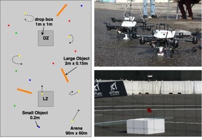
In this work we present a fully autonomous multi-agent aerial system to search and pick up small objects in environments similar as depicted in Fig. 2 which shows the complete system deployed at MBZIRC. The system consists of multiple building blocks relevant to SAR scenarios. The first block is multi-agent aerial exploration which includes agent allocation, coverage planning, globally consistent state estimation, and collision avoidance. The second block is aerial gripping which contains object detection, tracking, visual servoing, and physical interaction.
Multi-agent aerial exploration in an outdoor environment has four key requirements. It needs to cover the full area, be collision free, use limited network bandwidth, and be robust to agent failure. Thus we propose a decentralized system in which each agent is capable of fulfilling the task independently and share a minimum of information. Each agent is assigned to a predefined area following a camera coverage pattern. Visual-inertial odometry (VIO) fused with RTK-GPS gives accurate, high bandwidth, fail-safe state estimation in a common coordinate frame. The MAVs broadcast their position and velocity over the network which allows other agents to avoid them. This reactive avoidance scheme enables each agent to move freely without knowing the intention of the others explicitly.
The aerial gripping pipeline is based on object servoing which is independent of the underlying state estimation. Visual servoing allows correct positioning of the MAV relative to a target object without external information about its position. In particular, we present an object detection pipeline to retrieve the 3D position of objects from a single monocular detection and a simple yet precise servoing algorithm. The aerial gripping is complemented by an energy-saving, compliant electropermanent magnet (EPM) gripper design. Unlike regular electromagnets, EPMs only draw electric current while transitioning between the states.
The main contributions are
-
•
a modular, decentralized, collision-free multi-agent aerial search, pick up and delivery system,
-
•
formulation and evaluation of a complete image to position commands servoing pipeline for static and moving objects, and
-
•
evaluation and deployment of the system in different environments.
We organize the paper as follows. Section II presents related work. In section III we summarize our multi-agent system architecture and exploration strategy. In section IV we present the aerial gripping pipeline. The system hardware is described in the implementation details V. Finally, we validate our methods in section VI before we close the article with concluding remarks.
II Related Work
This work is a continuation of our previous work on aerial pick-up and delivery of magnetic objects [7]. While the previous work focused on developing a first running single prototype, this work presents a fully integrated multi-agent system with an improved gripper design and a new formulation of the servoing problem. In [7] we calculated the object position based on the MAV state relative to the object, here we calculate it solely from the detection.
Our proposed system follows similar design principles as other successful teams in MBZIRC. As in [8] we pick components that are easily adaptable, robust, and whose behavior can be interpreted and tuned by the operator.
We focus the rest of the review on the two main areas of our system: multi-robot aerial exploration and aerial gripping.
II-A Multi-Robot Aerial Exploration
Multi-robot 2D exploration in known environments is a common problem in outdoor surveying. Geometric solutions are complete, deterministic, computationally fast, and easily tractable. [9] discretize an area into viewpoints, assign each MAV to a subset of regions and use a wavefront planner for coverage. [4] use polygonal area decomposition and field of view (FOV) aware sweep planning to plan paths for cooperative MAV search operations. We implement a specific case of [4]’s coverage path planning (CPP), where we manually divide the workspace and have a fixed FOV.
In contrast to existing multi-robot systems, which usually assume collision-free planning by construction, we focus on the practical implications the decentralized picking scenario in a heterogeneous robot environment introduces: accurate global positioning and reactive collision avoidance in case of agent interference. For global positioning we fuse ROVIO [10] with RTK-GPS which gives more accurate longitudinal and lateral accuracy, reliable altitude information and fall back VIO positioning compared to standard IMU-GPS solutions [11]. For collision avoidance we choose reactive avoidance at the control level [12]. In comparison to centralized global planners like [13], this reactive approach requires significantly less communication and is safely embedded in the control framework.
II-B Aerial Gripping
Aerial gripping is a quickly growing field in MAV research. Different approaches exist both for the gripping mechanism as well as servoing and transportation. In [14] the authors present an integrated object detection and gripping system. They detect static objects using infrared LEDs and grab them using a form-closure mechanical design. In contrast, our system performs visual servoing from RGB images on both static and moving objects and aims at gripping ferrous objects with a magnetic gripper. In [15] the authors use a claw-like gripper to bring a MAV to a perching position, hanging from a pole. They use image based visual servoing. The control law is based entirely on the error in the image plane, no object pose estimation is performed. In contrast, we use pose based visual servoing. In this approach, the object pose is estimated from the image stream, then the robot is commanded to move towards the object to perform grasping. In [5, 16] the authors present multi-robot aerial systems for autonomous structure assembly. Both works have knowledge of object positions and operate open loop and centralized in a Vicon environment. We perform visual servoing to grasp objects under outdoor conditions in a decentralized system.
III Multi-robot Aerial Exploration
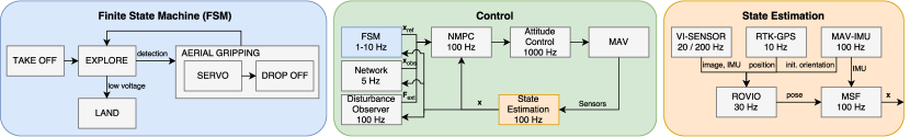
Our system architecture is visualized in Fig. 3. The robot’s brain is a decentralized finite state machine (FSM)that handles higher-level, single-agent task allocation and generates reference trajectory commands. The control loop processes trajectory commands and handles external disturbances and reactive collision avoidance. The state estimation pipeline provides the robot and other agents with consistent, global states. Each block in the system has a defined input and output and can be refined into smaller units, modularly replaced by advanced solutions, and tested separately. In the following we detail the three main blocks.
III-A Decentralized Finite State Machine (Blue)
Each agent acts independently of the other agents and all algorithms run onboard the MAV. After take-off it alternates between exploring a predefined area and greedily picking up and delivering objects. The robot lands when its battery voltage is below some threshold and it is currently not attempting to deliver an object.
To explore the arena, we separate it into three convex regions and implement a sweep planner as depicted in Fig. 4. The maximum distance between two line sweeps is calculated based on the camera’s FOV , the MAV altitude , and a user defined view overlap .
| (1) |

The field division creates a first safety layer for collision avoidance. However, interference between the agents can still occur in pick up situations or with other agents in a heterogeneous system. Therefore, we provide a second safety layer at the control level.
III-B Reactive and Adaptive Control (Green)
The control pipeline is based on a standard cascaded control scheme where a slower outer nonlinear model predictive position control (NMPC) loop controls a fast attitude control loop [17]. The position controller has three functionalities. It tracks the reference trajectory from the FSM requesting position and velocity commands, it compensates for changes in mass and wind with an extended Kalman filter (EKF) disturbance observer, and it uses other agents states for reactive collision avoidance [18, 12]. For the latter, the controller includes obstacles as a hard and soft constraint into the trajectory tracking optimization [12]. This paradigm can include arbitrary agent’s states and always ensure that a minimum distance is kept. Thus also other robots or obstacles can be avoided as long as they broadcast their state in a common frame over WiFi. Essentially, this is the only communication on the network.
III-C Global State Estimation (Orange)
In order to operate multiple agents in the same area they need to share positions in a common global coordinate frame. For this we integrate RTK-GPS position updates into our VIO pose estimation framework ROVIO [10]. This gives us drift-free, high-bandwidth, fail-safe, accurate global positioning.
The signal flow is depicted in the orange frame in Fig. 3. In a first step we initialize the VIO’s pose to the current GPS position and magnetometer orientation. During operation the framework then internally uses the position updates to correct the its pose estimate from VIO. Finally, Multi Sensor Fusion (MSF) fuses the global pose from ROVIO with the onboard inertial measurement unit (IMU) [19].
IV Aerial Gripping
A key component of our system is the object tracking and gripping pipeline. The MAVs need to accurately detect and servo to small moving and stationary discs from to altitude.
IV-A Object Tracking Pipeline
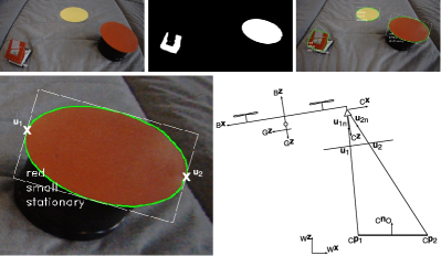
In order to locate colored objects, time-stamped RGB images are fed into our object detection and tracking pipeline. The pipeline outputs the 3D positions and the 2D horizontal velocities of the observed objects. The detection is visualized in Fig. 5 and the main steps of the pipeline are:
-
1.
Undistort the image and convert its pixel values from RGB to CIE L*a*b* color space for intuitive thresholding.
-
2.
Get the detections as the thresholded image regions.
-
3.
Classify the shapes based on contour properties.
-
4.
Remove outlier detections by their classification, shape-color inconsistency, and flight altitude-size inconsistency.
-
5.
Compute the inverse projection of the detections from 2D to 3D in camera coordinate frame (Sec. IV-B).
-
6.
Transform the object position from the camera coordinate frame to the world coordinate frame using the MAV pose and extrinsic camera calibration [20].
-
7.
Initialize a Kalman filter (KF) to track the position and velocity. Assign detections to already initialized KFs using the Hungarian algorithm [21].
IV-B Calculate 3D position from a Single Object Detection
Fig. 5 (bottom) displays the problem of calculating the position of two points on an object w.r.t the camera. To compute the 3D points and in the camera coordinate frame , we make two assumptions:
-
•
the points lie on a plane perpendicular to the world frame z-axis ,
-
•
the metric 3D distance between the two points is known.
These assumptions impose two constraints:
| (2) | ||||
| (3) |
where is the object normal expressed in the camera coordinate frame and is the rotation matrix from the camera coordinate frame to the world coordinate frame. Given the mapped points and in the image correspond to the points and , we write them as
| (4) | ||||
| (5) |
where and are arbitrarily scaled vectors pointing from the focal point to the points and computed through the perspective projection of the camera. For a pinhole-model the perspective projection from image coordinates to image vector is
| (6) |
where , is the principal point and , is the focal length obtained from the intrinsic calibration [20].
IV-C Object Servoing Pipeline
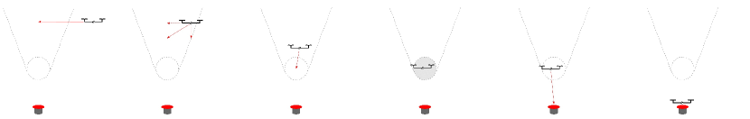
Once the agent detects an object in the exploration phase, it switches into servoing as depicted in Fig. 6. The servoing algorithm directly sends tracked x-y-object positions and velocities relative to the gripper frame to the controller. In order to keep the object in the FOV and to limit the descending motions, the z-position is constrained such that the MAV stays in a cone above the object. When the MAV is centered in a ball above the object, it activates the magnet and approaches the object using the current track as target position. During the descent it constantly remagnetizes the gripper to amplify the magnetic force on the object. The agent senses successful grasping using Hall sensors in the gripper.
V Implementation Details
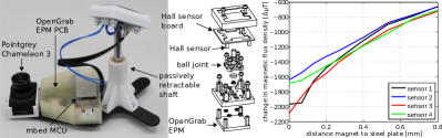
We run the system on the AscTec Neo hexacopters shown in Fig. 2. The Neos are equiped with a downward-facing PointGrey/FLIR Chameleon3 color camera ( in experiments, during MBZIRC) for object detection, a Skybotix VI-sensor and Piksi RTK-GPS receiver for state estimation, an Intel i5 for onboard processing, and a custom EPM gripper. The gripper-camera combination is depicted in Fig. 7. The gripper is designed to be lightweight, durable, simple, and energy efficient. Its core module is a NicaDrone EPM with a typical maximum holding force of on plain ferrous surfaces. The EPM is mounted compliantly on a ball joint on a passively retractable shaft. The gripper has four Hall sensors placed around the magnet to indicate contact with ferrous objects. The change in magnetic flux density indicates contact with a ferrous object as shown in Fig. 7. The total weight of the setup is . Unlike our previous version [7], the gripper is not compliant to non-planar surface geometries but it has simpler mechanics and its parts are more easily available.
VI Results
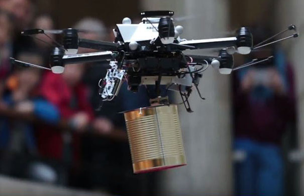
The partial and full system has been employed in various occasions among which were public demonstrations, field tests, and the MBZIRC (see Fig. 1 and Fig. 2). The modularity of the system allows reformulating the system for different applications. For example we employed it indoors using vision without GPS, or demonstrated only the aerial gripping. In the following we evaluate the individual components of the system and report briefly on our MBZIRC experience.
VI-A Multi-Robot Aerial Exploration
In this section we validate the reactive collision avoidance and the state estimation pipeline.
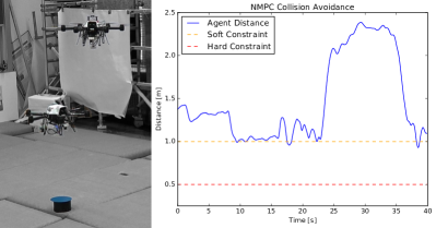
To evaluate the collision avoidance we let two drones attempt to servo to the same object. In Fig. 8 one can observe the distance between the MAVs. The prioritized MAV remains in the servoing position. The less prioritized MAV tries to enter the space but its position controller keeps it at a predefined distance of . This allows running different robotic systems in parallel without communicating each others intentions explicitly.
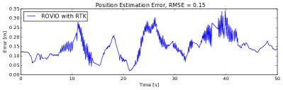
To evaluate the state estimation we compare a trajectory of our MAV with the ground truth position recorded with a Leica Totalstation in Fig. 9. Since the two trajectories have different time stamps and origins, we manually align them with respect to the root-mean-square error (RMSE). The RMSE compared to Leica is about which allows using the reactive collision avoidance paradigm.
VI-B Aerial Gripping
In this section we evaluate the 3D detection accuracy, the tracking, and the servoing sequence. The experiments are conducted in a Vicon motion capture environment for ground truth comparisons. Note that servoing is independent of the MAV state estimation.
Fig. 10 plots the detection error against different object positions in the image plane at different altitudes. Despite calibration errors and delay, we can achieve a position error of up to which is lower than the measuring accuracy for this setup. Low resolution and boundary effects like vignetting distort the blob detection and thus lead to larger errors and missing detections (depicted blank) at the image boundary. This emphasizes the importance of the centering step in the servoing pipeline.

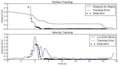
Fig. 11 shows the result of a single moving object pick-up. The object moves at a constant velocity of and enters the FOV. Detection errors on the image corners (see Fig. 10) cause tracking errors which converge against the ground-truth value when getting closer and centering above the object. The MAV approaches and grabs the object after activating the magnet.
VI-C MBZIRC
We scored second place in the MBZIRC where we engaged up to three MAVs simultaneously. We were able to collect both moving and static objects and at least two objects in each trial. On-site we only had two test slots and in total four trials to adjust our system to the environment. Thus tools for creating trajectories and tuning detection thresholds were mandatory. Also having a system as simple as possible was a great advantage in Abu Dhabi.
During the trials especially the servoing and control pipeline worked well. If an agent detected an object it generally servoed on spot even in windy runs.
Unfortunately, the EPM turned out to be too weak to always connect through the paint layer of the objects and the contact sensing sometimes failed due to wiring or limited response times. Furthermore, we faced CPU overload due to serialization of high resolution camera images. Not only did this prevent us from logging any data for debugging, but sometimes it even lead to delay and then divergence in the state estimation which made it hard to engage all MAVs simultaneously. The missing logs further prevented us from debugging detection issues which occured occasionally. While we could not foresee the magnet force issues, more elaborate testing before the event may have revealed all other issues.
VII Conclusion
We presented a fully autonomous aerial system to search, pick up, and relocate objects. Executing such complex task autonomously reduces operator effort and will eventually extend MAVs employment in real-life scenarios such as SAR. Reactive collision avoidance makes our system decentralized such that each agent can act independently with minimum communication. The agents are able to detect, track, and pick-up moving and static objects using monocular camera images and an EPM gripper. Modularity allows deploying the system in different environments and performing only subtasks. We employed the system in various outdoor and indoor events and evaluated its components individually in ground-truth experiments. Our system outperformed fifteen other systems at the MBZIRC where we became second.
Acknowledgment
This work was supported by the Mohamed Bin Zayed International Robotics Challenge 2017, the European Community’s Seventh Framework Programme (FP7) under grant agreement n.608849 (EuRoC), and the European Union’s Horizon 2020 research and innovation programme under grant agreement n.644128 (Aeroworks).
References
- [1] J. Qi, D. Song, H. Shang, N. Wang, C. Hua, C. Wu, X. Qi, and J. Han, “Search and rescue rotary-wing uav and its application to the lushan ms 7.0 earthquake,” in Journal of Field Robotics (JFR), vol. 33. Wiley, 2016.
- [2] G. De Cubber, H. Balta, D. Doroftei, and Y. Baudoin, “Uas deployment and data processing during the balkans flooding,” in International Symposium on Safety, Security, and Rescue Robotics (SSRR). IEEE, 2014.
- [3] I. Kruijff-Korbayová, L. Freda, M. Gianni, V. Ntouskos, V. Hlaváč, V. Kubelka, E. Zimmermann, H. Surmann, K. Dulic, W. Rottner et al., “Deployment of ground and aerial robots in earthquake-struck amatrice in italy (brief report),” in International Symposium on Safety, Security, and Rescue Robotics (SSRR). IEEE, 2016.
- [4] I. Maza and A. Ollero, “Multiple uav cooperative searching operation using polygon area decomposition and efficient coverage algorithms,” in Distributed Autonomous Robotic Systems (DARS). Springer, 2007.
- [5] Q. Lindsey, D. Mellinger, and V. Kumar, “Construction of cubic structures with quadrotor teams,” in Robotics: Science & Systems (RSS). IEEE, 2011.
- [6] M. Bernard, K. Kondak, I. Maza, and A. Ollero, “Autonomous transportation and deployment with aerial robots for search and rescue missions,” in Journal of Field Robotics (JFR), vol. 28. Wiley, 2011.
- [7] A. Gawel, M. Kamel, T. Novkovic, J. Widauer, D. Schindler, B. P. von Altishofen, R. Siegwart, and J. I. Nieto, “Aerial picking and delivery of magnetic objects with mavs,” in Conference on Robotics and Automation (ICRA). IEEE, 2017.
- [8] M. Nieuwenhuisen, M. Beul, R. A. Rosu, J. Quenzel, D. Pavlichenko, S. Houben, and S. Behnke, “Collaborative object picking and delivery with a team of micro aerial vehicles at mbzirc,” in European Conference on Mobile Robotics (ECMR). IEEE, 2017.
- [9] A. Barrientos, J. Colorado, J. d. Cerro, A. Martinez, C. Rossi, D. Sanz, and J. Valente, “Aerial remote sensing in agriculture: A practical approach to area coverage and path planning for fleets of mini aerial robots,” in Journal of Field Robotics (JFR), vol. 28. Wiley, 2011.
- [10] M. Bloesch, S. Omari, M. Hutter, and R. Siegwart, “Robust visual inertial odometry using a direct ekf-based approach,” in International Conference on Intelligent Robots and Systems (IROS). IEEE, 2015.
- [11] J. Wendel, O. Meister, C. Schlaile, and G. F. Trommer, “An integrated gps/mems-imu navigation system for an autonomous helicopter,” in Aerospace Science and Technology (AST), vol. 10. Elsevier, 2006.
- [12] M. Kamel, J. Alonso-Mora, R. Siegwart, and J. Nieto, “Nonlinear model predictive control for multi-micro aerial vehicle robust collision avoidance,” in arXiv preprint arXiv:1703.01164, 2017.
- [13] F. Augugliaro, A. P. Schoellig, and R. D’Andrea, “Generation of collision-free trajectories for a quadrocopter fleet: A sequential convex programming approach,” in International Conference on Intelligent Robots and Systems (IROS). IEEE, 2012.
- [14] V. Ghadiok, J. Goldin, and W. Ren, “Autonomous indoor aerial gripping using a quadrotor,” in International Conference on Intelligent Robots and Systems (IROS). IEEE, 2011.
- [15] J. Thomas, G. Loianno, K. Daniilidis, and V. Kumar, “Visual servoing of quadrotors for perching by hanging from cylindrical objects,” in Robotics and Automation Letters (RAL), vol. 1. IEEE, 2016.
- [16] F. Augugliaro, S. Lupashin, M. Hamer, C. Male, M. Hehn, M. W. Mueller, J. S. Willmann, F. Gramazio, M. Kohler, and R. D’Andrea, “The flight assembled architecture installation: Cooperative construction with flying machines,” in Control Systems, vol. 34. IEEE, 2014.
- [17] M. Achtelik, M. Achtelik, S. Weiss, and R. Siegwart, “Onboard imu and monocular vision based control for mavs in unknown in- and outdoor environments,” in Conference on Robotics and Automation (ICRA). IEEE, 2011.
- [18] M. Kamel, M. Burri, and R. Siegwart, “Linear vs nonlinear mpc for trajectory tracking applied to rotary wing micro aerial vehicles,” in arXiv preprint arXiv:1611.09240, 2016.
- [19] S. Lynen, M. Achtelik, S. Weiss, M. Chli, and R. Siegwart, “A robust and modular multi-sensor fusion approach applied to mav navigation,” in International Conference on Intelligent Robots and Systems (IROS). IEEE, 2013.
- [20] P. Furgale, J. Rehder, and R. Siegwart, “Unified temporal and spatial calibration for multi-sensor systems,” in International Conference on Intelligent Robots and Systems (IROS). IEEE, 2013.
- [21] H. W. Kuhn, “The hungarian method for the assignment problem,” in Naval Research Logistics (NRL), vol. 2. Wiley, 1955.