Mode Control in a Multimode Fiber Through Acquiring its Transmission Matrix from a Reference-less Optical System
Abstract
A simple imaging system together with complex semidefinite programming is used to generate the transmission matrix of a multimode fiber. Once the transmission matrix is acquired, we can modulate the phase of the input signal to induce strong mode interference at the fiber output. The optical design does not contain a reference arm and no interferometric measurements are required. We use a phase-only spatial light modulator to shape the profile of the propagating modes and the output intensity at an individual pixel is monitored. The semidefinite program uses a convex optimization algorithm to generate the transmission matrix of the optical system using intensity only measurements. This simple yet powerful method can be used to compensate for modal dispersion in multimode fiber communication systems. It also yields great promises for the next generation biomedical imaging, quantum communication, and cryptography.
pacs:
Valid PACS appear hereA monochromatic light beam launched into a multimode fiber (MMF) typically excites many modes in the waveguide. The set of modes excited depends on the coupling conditions at the input of the fiber. Each guided mode travels down the waveguide with a different group velocity. As a result, the information carried by each mode arrives at the end of the fiber at a different time. This phenomenon is known as modal dispersion (MD). In a multimode fiber optical communication system, the dominant factor limiting the achievable bandwidth is interference between channels caused by MD agrawal . Thus precise modal excitation and control is of great interest for improving the transmission capacity of MMF.
Mode control has been previously demonstrated using binary phase masks to characterize and suppress MD in MMF carpenter . Recently, a variety of new methods using digital phase conjugation papa ; farahi and wavefront shaping techniques antonio (and references therein) have shown precise mode control in MMF endoscopes.
Due to unpredictable mode coupling arising from fabrication defects, bends, and temperature fluctuations, MMF endoscopes require rigorous calibration procedures to enable imaging.
Therefore, implementing a simple and accurate method to control light propagation inside the fiber is desired.
When the phase delay among multiple propagating modes varies over the entire range of 2 radians, highly structured interference effects or speckle patterns are detected at the output of the fiber goodman , analogous to those observed in turbid media.
For this reason, many approaches to wavefront shaping through highly scattering media ivo can be applied to light propagation in MMF. These include the determination of the transmission matrix (TM) in linear scattering systems popoff ; gigan .
The TM of a MMF connects the modes of the input signal coupled into the fiber to the outgoing modes collected at the output of the fiber. Since the number of modes in a MMF is well defined and the numerical aperture (NA) is limited, the fiber TM can be completely measured. Complete knowledge of the TM enables unprecedented control of propagation through MMF.
Knowledge of the TM have been used to modulate the signal at the fiber input to generate sharp foci at the fiber output silvio ; cizmar ; papa , and to transmit images silvio1 ; choi ; joel through the fiber. The TM method has also been used to design robust and light efficient single MMF endoscopes yugu ; antonio .
Measuring the TM has also been proposed as an approach to controlling modal dispersion milione by enabling selective launching of the principal modes of the fiber cao . The principal modes in a MMF form an orthogonal basis at both the input and output of the waveguide and do not suffer from MD fan .
The TM has also been used to control the propagation of two photon or quantum light through a MMF hugo .
Most techniques to date use variations of the interferometric method to generate the transmission matrix of the MMF; however, in a telecommunication environment where MMF play a major role for data transport, these techniques can be very difficult to implement.
Therefore, methods to determine the TM without the need for a reference beam would be tremendously useful, and the development of algorithms for signal recovery from magnitude measurements in a realistic telecommunication system is desirable.
Simulations results, using parameters of commercially available fibers and SLMs, have shown elad ; shen ; rahul ; rahul09 that modal dispersion can be eliminated in a MMF optical communication system using adaptive optics and convex optimization, but they do not infer the TM of the optical system.
In this paper, we determine the TM of a MMF using a simple optical setup and employing a semidefinite programming (SDP) algorithm which uses convex optimization.
This paper builds on our previous work in ngom . The method therein only computes the relevant portion of the transmission matrix where for example a strong focus is desired, rather than generating the ‘whole’ TM. The full TM can also be computed but for efficiency and speed, only the relevant portions are computed.
We utilize a spatial light modulator (SLM) to control the phase of the input signal. The SLM pixels are grouped into a square array of superpixels, where the number of superpixels is chosen to be approximately equal to the number of the MMF modes. The phase is constant over each superpixel. The goal is to find the optimum set of phases for each superpixel that produces the desired output, which can be obtained by knowledge of the system’s TM.
We adapt the algorithm developed by Waldspurger et al irene to retrieve the phase of elements of the TM from measurements of the light intensity at the output face of the MMF.
Hence knowledge of the TM enables the SLM to excite specific modes while suppressing others. This method will minimize modal dispersion in the system and improve the signal to interference ratio in the MMF channel elad ; rahul09 .
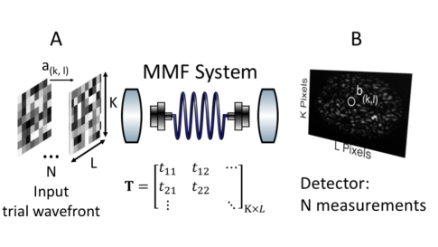
Fig 1 illustrates the mode control scheme.
The computed transmission matrix links the input fields at each superpixel to the output fields at the detector. incorporates the propagation from the SLM to the detector including the fiber and the imaging optics.
Apertures and , as displayed in Fig 1, are assumed to be rectangular and are comprised of elements. Light in the input and output apertures are characterized by complex-valued electric field samples and respectively, with . Our experimental setup only allows for measurements of the magnitude of each .
We will next proceed to give an overview of the algorithm, which we have described in detail elsewhere ngom . The method therein only computes the relevant portion of the transmission matrix where for example a strong focus is desired rather than generating the ‘whole’ TM.
The fields in and are connected in amplitude and phase by the TM of the optical system,
| (1) |
where vector and . The TM in Eq. 1 is usually generated by determining the amplitude and phase of the output fields by an interferometric measurement (see reference gigan for a comprehensive review).
In an actual fiber telecommunication network however, establishing an interferometric system is highly nontrivial, motivating the need to determine the TM of the system without requiring a reference arm.
Intensity measurements only allow for the observation of
| (2) |
so the phase of is undetermined, necessitating an approach to phase retrieval.
Solving for is a phase retrieval problem, which can be divided into sub-problems of solving each row of the TM . Each row corresponds to a pixel on the detector. In a telecommunication system each pixel in the detector represents a channel, and each row of the TM is assigned to an individual receiver in the system.
The task is to compute an incident field that ‘forces’ the modes of the fiber to constructively interfere at a predefined location at the output. Mathematically, the goal is to determine the input field vector that maximizes for a predefined subject to . Only the input phases are controlled, i.e. for all .
To solve for the row of for a predefined , we generate random input fields or training wavefronts with . All input fields have uniform magnitude across the input aperture, and the phases of the input modes are varied randomly between .
Recovering T, given and , as in Eq 2 is a non-convex problem. By recasting this problem as a SDP, which we accomplish by adopting PhaseCut irene as in ngom , we transform the transmission matrix recovery problem in a convex optimization problem.
It has been shown that, if the number of measurements is of order , then PhaseCut will recover the phase vector with high accuracy in a noise-free setting when the training wavefronts are generated at random irene , as we have.
The phase-only incident field vector that maximizes at a predefined channel at the output of the fiber corresponds to:
| (3) |
Eq. (3) has a closed-form solution that is given by
| (4) |
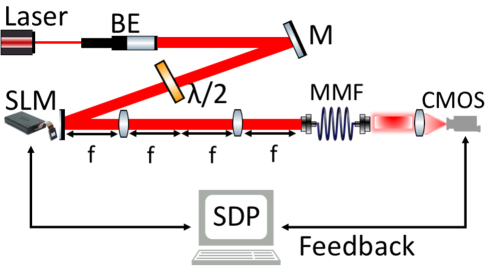
where
Fig. 2 shows the simple optical design we use to measure the TM of the MMF system. In the experiment, we use a 2 meter long step index fiber (Thorlabs M50L02S-A), with a numerical aperture (NA) = 0.22. The core diameter of the fiber is . The number of supported modes is given by in each polarization direction, where is the normalized optical frequency, also known as the V-number of the fiber, . The light source is a single longitudinal mode diode laser (CrystalLaser) producing 50 at . The output beam of the laser is expanded by a beam collimator and reflected onto the SLM (Holoeye PLUTO), which is a liquid crystal on silicon (LCOS) micro-display with full HD resolution (1920 x 1080 pixel) and 8 pixel pitch. A waveplate and a polarizer are used to control the polarization state of the incident beam to achieve phase only modulation. The surface of the SLM is imaged onto the entrance face of the fiber. The SLM display is subdivided into superpixels, i.e. each superpixel contains an equal number of SLM pixels that are modulated together. The output signal from the MMF is imaged onto a CMOS camera (PhotonFocus camera series MV1-D2048 with 2048 X 2048 resolution and pixel size 8 ).
The experimental results presented here are obtained by subdividing the SLM into superpixels. A Sequence of random training wavefronts are injected into the MMF. A waveplate is used to adjust the polarization of the incident light to match that of the desired fiber modes. The fiber is coiled tightly to induce randomized mode coupling.
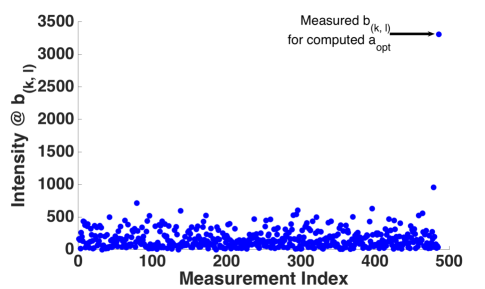
For each incident wavefront the superpixels’ phases are randomly set between ; their corresponding transmitted intensities are measured at pixel . Fig. 3 shows the intensity output response for the training wavefronts coupled into the MMF input.
Each training wavefront generates its own unique intensity or speckle pattern. Fig. 4 shows a typical speckle pattern that emerges from a MMF.
The intensity measurements are collected, transformed, and fed into the SDP program, which then computes the relevant row of the TM.
The next objective is to couple into the fiber the optimal wavefront from Eq. 4 that forces the propagating modes to interfere at a predetermined position.
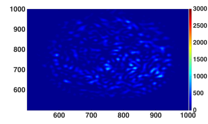
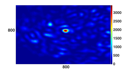
Fig. 3 shows that the computed optimal wavefront generates the highest intensity measurement at the targeted position on the detector. Fig. 4 displays the strong interference of the controlled modes near the center of fiber output. The size of the focus spot is determined by the N.A. of the optical system. The enhancement factor at the focus is defined as :
| (5) |
where is the intensity at when is coupled into the MMF and is the average intensity at pixel over the training realizations. The strong interference is displayed in Fig. 4, this yields an enhancement factor of .
The data clearly demonstrates that the modes coupled in the fiber can be controlled and redirected or refocused into a useful transmitted mode.
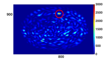
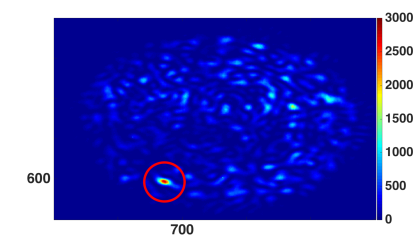
In principle this method allows the controlled modes to interfered anywhere at the fiber output or to any channel in a telecommunication system. For example
Fig. 5 and 5 show interference spots at other locations obtained from the same TM measurements but with different optimal wavefront . In other words, a single TM enables focusing the signal at any desired output location.
SDP together with faster SLM systems (MEMS and/or micromirrors) could constitute an adaptive optics approach to compensate for modal dispersion in telecommunication.
This design would provide dynamic modal compensation when the state of the modes inside a MMF evolves as the fiber changes in response to slow time-varying perturbations, e.g., temperature and vibration.
In summary, we have demonstrated a non-holographic method to compute the TM of a multimode optical fiber system. Obtaining the complete transmission matrix of a fiber system without the use of a reference arm will be an important milestone in the burgeoning field of wavefront shaping. The simplicity of this method has the potential of enhancing the design of single multimode fiber endoscopes, and to improve in-vivo characterization in biomedical imaging. A great impact can also be made in fiber telecommunication systems with the promise to further increase the bandwidth in MMF by compensating for modal dispersion. Once the TM of the MMF is acquired using this dynamic adaptive optics method, the principal modes of the fiber can be inferred and launched on demand.
Acknowledgements
This work was supported by a DARPA Young Faculty Award D14AP00086. The authors also thank the creators and the maintainers of the website http://wavefrontshaping.net/ – the many tips and suggestions and software posted there allowed for this project to come together sooner than it would have otherwise.
References
References
- (1) G. P. Agrawal, “Fiber Optic Communication Systems”, Third Edition, John Wiley & Sons, Inc. (2002).
- (2) J. Carpenter and T. D. Wilkinson, J. Light. Tech., Vol. 30, No. 10 (2012).
- (3) I. N. Papadopoulos, S. Farahi, C. Moser, and D. Psaltis, Biomed. Opt. Exp. Vol. 4, No. 2 (2013).
- (4) S. Farahi, D. Ziegler, I. N. Papadopoulos, D. Psaltis, and C. Moser, Opt. Exp. Vol. 21, No. 19 (2013).
- (5) A. M. Caravaca-Aguirre and R. Piestun, Opt. Exp., vol. 25, No. 3, (2017).
- (6) J. W. Goodman, “Speckle Phenomena in Optics”, Roberts and Co. Publishers, (2006).
- (7) I. M. Vellekoop, Opt. Exp., Vol. 23, No. 9, (2015).
- (8) S. Popoff, G. Lerosey, R. Carminati, M. Fink, A. Boccara, S. Gigan, Phys. Rev. Lett. 104 (2010) 100601.
- (9) Stefan Rotter and Sylvain Gigan, Rev. of Mod. Phy., Vol 89, (2017).
- (10) S. Bianchi and R. Di Leonardo, Opt. Express 19, 247, (2011).
- (11) T. Čižmár and K. Dholakia, Opt. Express 19, 18871 (2011).
- (12) S. Bianchi and R. Di Leonardo, Lab Chip 12(3), 635–639 (2012).
- (13) Y. Choi, C. Yoon, M. Kim, T. D. Yang, C. Fang-Yen, R. R. Dasari, K. J. Lee, and W. Choi, Phys. Rev. Lett. 109(20), 203901 (2012).
- (14) J. Carpenter, B. J. Eggleton, and J. Schöder, Opt. Exp. 96, Vol. 22, No. 1 (2014).
- (15) R. Yu Gu, R. N. Mahalati, and J. M. Kahn, Opt. Exp., Vol. 23, No. 21 (2015).
- (16) G. Milione, D. Nolan, and R. Alfano, J. Opt. Soc. Am. B., Vol. 32, No. 1 (2015).
- (17) W. Xiog, P. Ambichl, Y. Bromberg, B. Redding, S. Rotter, and H. Cao, Phys. Rev. Lett. 117, 053901 (2016).
- (18) S. Fan and J. M. Kahn, Opt. Letts. Vol. 30, No. 2 (2005).
- (19) H. Defienne, M. Barbieri, I. A. Walmsley, B. J. Smith, S. Gigan, Sci. Adv. 2016; 2 : e1501054. (2016).
- (20) E. Alon, V. Stojanovic, J. M. Kahn, S. P. Boyd, and M. A. Horowitz, in Proc. Global Telecommun. Conf., Dallas, TX, Nov. 2004, vol. 2, pp. 1023?1029.
- (21) X. Shen, J. M. Kahn, and M. A. Horowitz, Opt. Lett. Vol. 30, No. 22 (2005).
- (22) R. A. Panicker, J. M. Kahn, S. P. Boyd, J. Light. Tech., Vol. 26, No. 10 (2008).
- (23) R. A. Panicker and J. M. Kahn, J. Light. Tech., Vol. 27, No. 24 (2009).
- (24) M. N’Gom, MB Lien, N. M. Estakhri, T. B. Norris, E. Michielssen, R. R. Nadakuditi, Nat. Sci. Rep. Vol. 7, No. 1, 2518 (2017).
- (25) I. Waldspurger, A. d’Aspremont, S. Mallat, Math. Program., Ser. A (2015) 149 : 47 – 81.
- (26) Grant M and Boyd S 2010 CVX: Matlab software for disciplined convex programming, version 1.21 http://cvxr.com/cvx