∎
e1e-mail: francesco.renga@roma1.infn.it
The Quest for and its Experimental Limiting Factors at Future High Intensity Muon Beams
Abstract
The search for the Lepton Flavor Violating decay will reach an unprecedented level of sensitivity within the next five years thanks to the MEG-II experiment. This experiment will take data at the Paul Scherrer Institut where continuous muon beams are delivered at a rate of about muons per second. On the same time scale, accelerator upgrades are expected in various facilities, making it feasible to have continuous beams with an intensity of or even muons per second. We investigate the experimental limiting factors that will define the ultimate performances, and hence the sensitivity, in the search for with a continuous beam at these extremely high rates. We then consider some conceptual detector designs and evaluate the corresponding sensitivity as a function of the beam intensity.
1 Introduction
The search for lepton flavor violation in charged lepton decays like plays a crucial role in the search for physics beyond the Standard Model (SM). The conservation of the lepton flavor is an accidental symmetry in the SM and is generally broken in new physics (NP) models, which are already strongly constrained by the present limits. The discovery of neutrino oscillations already demonstrated that this symmetry is not exact, although the impact on the charged lepton sector is negligible, predicting for the decay a branching ratio (BR) of about , far away from the present experimental limit, meg_analysis , obtained by the MEG collaboration at the Paul Scherrer Institut (PSI, Switzerland).
These features make the search for charged Lepton Flavor Violation (cLFV) very attractive: on one side, limits on hugely impact the development of NP models; on the other side, an observation of this or any other cLFV decay would be an unambiguous evidence of NP Lindner:2016bgg , without any theoretical uncertainty.
In the search for cLFV in muon decays, a central role is played by the availability of high intensity continuous muon beams,111In this paper we concentrate on the search for cLFV in the decay of free muons, and in particular , which requires a continuous muon beam, and hence we do not discuss the efforts made to deliver very high intensity pulsed muon beams, e.g. for the search of conversion in the Coulomb field of a nucleus. and there are activities around the world himb ; music ; pip-ii to increase the beam rates to eventually reach muons per second. In this context, it is crucial to understand which factors will limit the sensitivity of experiments to be run at these facilities in the future. In this paper we concentrate on the searches. After briefly reviewing the current experimental status and the ongoing efforts to build high intensity continuous muon beam lines, we will investigate the ultimate experimental resolutions and efficiencies which cannot be realistically surpassed with the current experimental concepts, even considering some incremental improvement in the detection techniques. Moreover, we will shortly discuss how these ultimate performances could be technically reached. Finally, we determine the sensitivity which could be obtained if the proposed strategies will be found to be technically feasible.
2 Basics of searches
The largest step in sensitivity was due to the transition from the search in cosmic muon decays (rate of the order of Hz) to muons from stopped pion beams (four orders of magnitude higher rate) and eventually to muon beams (two further orders of magnitude). Within each beam configuration the improvements of the detector resolutions, which determine the background rejection capability, were fundamental.
Muons are usually stopped in a target, in order to exploit the very clear signature of a decay at rest: an and a in coincidence, moving collinearly back-to-back with their energies equal to half of the muon mass (/2 = 52.8 MeV). The searches are carried out by using positive muons: negative muons cannot be used, since they are captured by nuclei while being stopped in the target.
There are two major sources of background events. One is the radiative muon decay (RMD), , when the positron and the photon are emitted almost back-to-back while the two neutrinos carry off little energy. The other is due to the accidental coincidence of a positron from a Michel muon decay, , with a high energy photon, whose source might be either a RMD, the annihilation-in-flight (AIF) of a positron in a Michel decay or the bremsstrahlung from a positron.
To separate the signal from the various background events, four discriminating variables are commonly used. The positron energy , the photon energy and the relative angle allow to reject both accidental and RMD events, while the further request of a tight time coincidence between the positron and the photon (relative time = 0) helps by reducing the accidental background. It is also important to notice that these variables are not correlated for accidental background events, and poorly correlated for RMDs on the scale of the detector resolutions, while in signal events there is a precise expectation value for each of them. This makes it advantageous to use them separately in a statistical analysis, instead of combining them into an invariant mass.
In the four-dimensional space of these discriminating variables a signal region can be defined around their expectation values for the signal events, with widths , , and which can be taken proportional to the corresponding resolutions. Hence, the impact of the resolution on each variable can be quantified, considering the rate of accidental events falling in this signal region. According to kuno-okada ; bernstein , this rate satisfies:
| (1) |
where is the muon stopping rate. This expression is derived considering the photons from RMD, whose rate can be precisely predicted based on the RMD theoretical BR and the detector acceptance, with only minor corrections meg_rmd . For AIF photons, the absolute rate depends on the material crossed by the positrons along their trajectory, and hence on the details of the detector layout.
A crucial element of Eq. 1 is the dependence on the square of . Given the current detector resolutions, and with the large values of available at the present facilities, the accidental background is largely dominant over the prompt RMD contribution. Even imagining a sensible improvement of the resolutions, this is likely to be the case also for the future facilities, when is increased by one or two orders of magnitude. Under these conditions, there are two regimes for the expected experimental sensitivity. If one indicates with the background yield in the signal region over the data-taking period of the experiment (), the sensitivity improves linearly with the beam rate, as far as (efficiency-dominated regime). On the other hand, as soon as , there is no advantage from a further increase of the , since the ratio of the signal yield over the square root of the background yield remains constant (background-dominated regime). Indeed, the increased pile-up of several muon decays in the same event would even deteriorate the detector performances. Hence, for a given detector, the optimal is the one for which no more than a few background events are expected over . From another point of view, for a given , the best compromise between resolutions and efficiency is the one giving a few expected background events, because it implies an optimal use of the available beam.
Some further considerations must be added to the discussion above.
-
1.
Tracking detectors can be used to determine precisely the positron direction, but photon detectors cannot provide by themselves a precise determination of the photon direction, to be used in the determination of the angle. Hence, the following procedure is used: muons are stopped in a planar target, the intersection of the positron track with the target plane (positron vertex) is taken as the muon decay point and the photon direction is taken as the vector going from the muon decay point to the photon detection point. Hence, the resolution is determined by the positron vertex resolution and the photon detection point resolution.
-
2.
depends on the square of both the and resolution. In the first case this dependence arises from the quick drop of the RMD and AIF photon spectra at the kinematic end point. In the second case this can be understood by decomposing in its two independent projections, an azimuth angle and a polar angle . This dependence implies that even a small improvement in the resolution of these variables can have a significant impact on the sensitivity.
-
3.
The rate of AIF photons, which tends to be dominant at the kinematical end point kuno-okada , depends on the material crossed by the positrons on their trajectories (including positrons out of the detector acceptance and/or produced off-target). Hence, it is crucial to design the detector in order to have the lowest possible material budget, not only in the tracking volume (as needed for good positron resolutions), but in any region around the beam line, in particular near the target. The target itself has to be considered as the main source of AIF photons.
-
4.
Depending on the reconstruction techniques, further discriminating variables can be introduced to suppress the accidental background. If the photon detector allows an even rough reconstruction of the photon trajectory, the likelihood of the photon and positron to come from the same vertex can be evaluated. It would help to further discriminate between signal and accidental background events. In this case, Eq. 1 becomes dejongh :
(2) where is the angular resolution of the photon detector.
The last point above brings us to the discussion of the reconstruction techniques. Concerning the positron, the choice is between charged particle tracking in a magnetic spectrometer and calorimetry, and it is exclusively driven by the achievable resolutions: efficiencies are in fact comparable and potentially close to 100% in both cases. Conversely, for the photon the interplay between efficiency and resolution has to be carefully considered. A calorimetric technique was adopted in most of the past experiments, including MEG meg-detector with its Liquid Xenon (LXe) detector. This approach provides a large efficiency, only limited by the amount of material in front of the detector ( 1 in MEG). However, a different technique was used in MEGA mega , a previous experiment performed at the Los Alamos National Laboratory: thin layers ( 0.1 ) of high-Z material were used to make the photon convert, and the resulting pair was tracked in a magnetic field. The conversion efficiency is very low (few %), but this technique provides a very precise energy measurement, an extremely precise conversion point measurement and some information about the direction of the photon. Depending on the sensitivity regimes described above, these very good resolutions can compensate the loss in efficiency. Therefore, if is so low that the can be reduced to a negligible level with a calorimetric technique, there is no real advantage from a large improvement of the resolutions, when it comes at the price of a large efficiency loss. But in a high regime, when the calorimetric measurement would give too many background events, a strong improvement of the resolutions is the only way to really exploit the highest , because in this scenario it can compensate the concurrent efficiency loss.
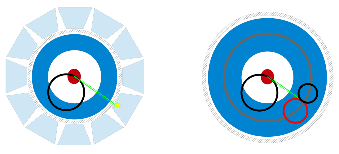
Fig. 1 shows how a typical detector can be designed to exploit either the calorimetric or conversion technique. In both cases, in order to measure precisely the time of the positron, fast detectors need to be placed at the end of the positron trajectory (not shown in the picture). If the photon is reconstructed in a calorimeter, a fast scintillator needs to be used in order to extract a good measurement of the photon time. Options for timing with the conversion technique will be discussed in detail in Sec. 4.
A real-life example is the MEG experiment: positrons were tracked by a set of 16 planar drift chambers, in order to reconstruct their momentum and direction, and they finally reached a set of scintillating bars for timing purposes, while photons were detected inside a LXe calorimeter instrumented with PMTs, allowing to measure their energy, time and conversion position.
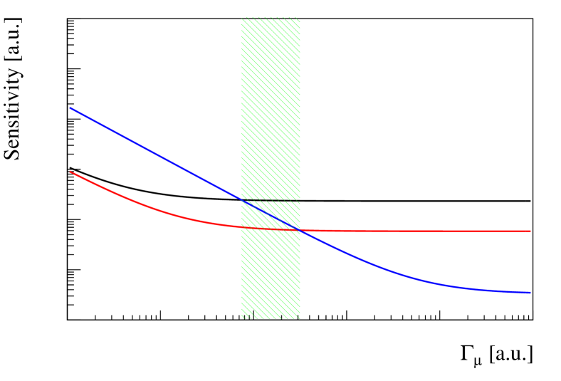
Some concepts presented above are illustrated in Fig. 2. The sensitivity is the smallest BR that can be excluded at some confidence level. The black line shows it for a hypothetical experiment based on the calorimetric technique against the , for a fixed . As discussed above, the sensitivity saturates at large . The blue line shows instead the sensitivity of an experiment having 1/20 photon efficiency but 10 times better and resolutions, like in a photon conversion approach. For low the calorimetric approach overcomes the photon conversion, but for very high the latter is advantageous. Notice that there is also an intermediate range (green-hatched area) where a moderate improvement in calorimetry (a factor 2 in resolutions for this example, red line) can bring this solution back to be preferable. This is exactly what happened with the introduction of LXe calorimetry in MEG after the use of photon conversion in MEGA.
The MEG experiment is currently being upgraded (MEG-II, meg2 ) with the same detector concept but several improvements which will push the sensitivity down of about one order of magnitude in three years of data taking. The main improvements with respect to MEG are: a 2 m-long single-volume cylindrical drift chamber, to improve the tracking resolutions and the positron efficiency; a finer photon detector granularity at the inner face of the calorimeter, to improve the position and energy resolution and the pile-up rejection capabilities of the detector; a highly segmented positron timing counter, to improve the positron time resolution with multiple measurements along the particle’s trajectory.
3 The next generation of high intensity muon beams
The current best limit on the BR comes from the MEG experiment, operated at the E5 beam line at PSI. Muons originate from the decay of pions produced by a proton beam impinging on a graphite target. The E5 channel is tuned to select positive muons with an average momentum of 28 MeV/c and a momentum bite of 5-7% FWHM. This setup allows the selection of muons produced by pions decaying right at the surface of the graphite target, providing high beam intensity and optimal rejection of other particles. A rate of muons/s can be obtained, but is was limited to muon/s in MEG, as this gave the best sensitivity, according to the discussion in Sec. 2. In MEG-II will be increased to muons/s, thanks to the improved resolutions of the upgraded detectors. Another beam line (E4) is also operated at PSI, with the capability of delivering up to muons/s.
In the meanwhile, an intense activity is ongoing at PSI and elsewhere to design channels for continuous muon beams with exceeding muons/s and possibly reaching muons/s.
At PSI, the High-intensity Muon Beam (HiMB) project himb intends to exploit:
-
1.
an optimized muon production target;
-
2.
a higher muon capture efficiency at the production target (26% versus 6% in the existing E4 channel), thanks to a new system of normal conducting capture solenoids;
-
3.
a higher transmission efficiency (40% versus 7% in E4), thanks to an improved design of the beam optics.
Given the present in E4, muons/s in the experimental area, the goal of muons/s seems to be within reach.
At PSI, muons are produced on a relatively thin target (20 mm), since the beam has to be preserved for the subsequent spallation neutron source, SINQ. At RCNP in Osaka (Japan), the MuSIC project music makes use of a thicker target (200 mm), exploiting maximally the much lower proton beam intensity. The target is surrounded by a high-strength solenoidal magnetic field in order to capture pions and muons with a large solid angle acceptance. Moreover, the field is reduced adiabatically from 3.5 T at the center of the target to 2 T at the exit of the capture solenoid in order to reduce the angular divergence of the beam and hence increase the acceptance of the solenoidal muon transport beam line. Tests have been performed, showing that muons per Watt of beam power can be obtained. At the full beam power which is available at RCNP, a rate of muons per second is expected at the production target, in the full momentum spectrum. The transport of the muons to the experimental areas and the selection of surface muons will reduce significantly this rate. Nonetheless, it is a good example of the alternative approach for the production of intense continuous muon beams, with lower power of the primary proton beam (400 W at MuSIC, to be compared with the 1400 kW power of the PSI proton accelerator) but a much higher muon yield per unit of power, thanks to the thicker muon production target. A compromise between the two approaches could open interesting future perspectives for a further increase of the beam rates.
Ideas to perform searches for and have been also proposed in the framework of the PIP-II project at FNAL pip-ii ; snowmass . To the best of our knowledge, a realistic design of a continuous muon beam line at this facility and a reliable estimate of the achievable muon beam rates are not yet available in the literature. Nonetheless, there are indications that this facility could be competitive with the PSI HiMB project.
These recent developments will give the possibility of running searches with muon beams one or two orders of magnitude more intense than what is presently available.
4 Experimental limiting factors
In this Section we try to identify the factors which will ultimately limit the sensitivity of the next generation experiments. In this respect, we will only marginally consider the intrinsic performances of the specific detection techniques (single hit resolutions, etc.), which will be better discussed in the next sections. Conversely, our goals are to find the experimental factors (interaction with materials, etc.) which will not improve automatically with the technological evolution of the detectors, and to identify the experimental issues which will require a technological breakthrough in order to be addressed. Besides providing the basic information to estimate the potential sensitivity of the next generations of searches, this discussion will give some directions towards a more radical step forward.
4.1 Efficiency
The discrimination between signal and background events can be made through a maximum likelihood fit, as shown in MEG meg_analysis , with only a small loss of signal. The signal efficiency is therefore dominated by the positron and photon reconstruction efficiencies, and .
The first element affecting and is the geometrical acceptance of the detector. Due to the back-to-back signature of the signal, the detector can be designed in such a way that, for signal events, positrons never escape the detection if the photon is within the detector acceptance, or vice versa. So, one of the two sub-detectors unequivocally defines the detector acceptance. While in principle there is nothing preventing to have an almost full angular coverage, apart from a small region around the beam axis, costs can provide a strong limit. The MEG experiment, for instance, only had a 10% acceptance, limited by the angular coverage of the (very expensive) LXe calorimeter. Though mitigated, this point could be relevant also for the innovative crystals we will discuss in Sec. 5.1.
When photons are within the acceptance, a fraction of them generate a shower before entering the detector. This is mainly due to the material in front of the detector (photon detectors and the magnet coil of a positron spectrometer are typically placed in front of the active volume of the calorimeter). A reconstruction efficiency of was obtained in MEG, but different detector desings with lighter photon detectors could significantly improve this figure in the future.
Moreover, at larger , the necessity of rejecting pile-up events implies some signal inefficiency. At muons per second, could be dominated by the superposition of two RMD photons, with a total energy above 50 MeV, impinging on the photon detector, and the signal efficiency of the necessary pile-up rejection algorithms could be relevant. An estimate of these effects largely depends on the specific detector design.
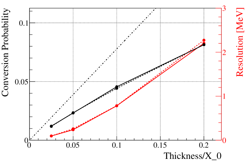
The situation is completely different if the photon conversion technique is adopted. Thin converters are needed in order to preserve very good resolutions. It implies in turn a few percent . In Fig. 3 the conversion probability for 52.8 MeV photons in lead and tungsten for different thicknesses are shown. It must be noticed that, due to the relatively low energy of the photons, this probability is lower than the high-energy asymptotic value ( times the thickness in units of radiation lengths). Moreover, both the electron and the positron produced in the photon conversion have to be sufficiently energetic to be efficiently tracked. Considering that a typical tracking detector will have a few mm granularity along the track direction, only tracks with at least a few MeV can be reconstructed in a magnetic field of 1 T. Although the magnetic field can be optimized, a low momentum cutoff is unavoidable and, for instance, the requirement that the electron and the positron energies are both larger than 5 MeV further reduces by a factor .
Concerning the positron from the muon decay, both tracking and calorimetry usually provide very large . Inefficiencies, however, can arise when the track is propagated from the last measurement point in the tracking detector to the positron timing detector. Multiple Coulomb scattering (MS) or energy loss () might be dramatic and introduce large inefficiencies in the matching between the spectrometer and the timing detector. In MEG this effect was particularly important and reduced by a factor of two.
4.2 Photon energy
Calorimetry. The resolution is dominated by the photon statistics. Hence, the light yield determines the choice of the scintillator to be used, along with the fast response that is needed in order to reach a very good time resolution. Tab. 1 summarizes the relevant properties of some state-of-the-art scintillating materials.
A degradation of the resolution due to the stability of the energy scale can be avoided with an accurate and frequent multi-channel calibration. In MEG this enabled the scale to be kept stable to within 0.2%.
| Scintillator | Density] | Light Yield | Decay Time |
|---|---|---|---|
| [g/cm3] | [ph/keV] | [ns] | |
| LaBr3(Ce) | 5.08 | 63 | 16 |
| LYSO | 7.1 | 27 | 41 |
| YAP | 5.35 | 22 | 26 |
| LXe | 2.89 | 40 | 45 |
| NaI(Tl) | 3.67 | 38 | 250 |
| BGO | 7.13 | 9 | 300 |
Pair conversion. The limiting factor of the resolution is the interaction of the pair within the material of the photon converter itself. Indeed, just after the conversion, the electron and the positron lose energy before exiting the converter. The fluctuation predominantly contributes to the resolution, since is estimated as the sum of the and energies (in some previous studies like caltech this contribution was disregarded caltech-private ). According to our GEANT4 geant4 simulations, a 280 m Pb layer (), with photon conversions happening uniformly along the thickness of the converter, would give a resolution of keV in the limit of perfect tracking of the pair. In Fig. 3 the contribution of the material effects to the resolution is also shown versus the layer thickness for lead and tungsten, along with the total conversion probability. The resolution is evaluated as a truncated RMS of the reconstructed energy distribution, after discarding 20% of the events in the low energy tail.
Considering that a lower thickness improves the resolution but also lowers , an optimization is necessary. As pointed out in dejongh , the background rate is expected to scale with the third power of the converter thickness , while scales linearly. So, one can try to maximize a Punzi figure of merit punzi :
| (3) |
where is the background yield expected with at given and . Typical choices of are or . This function has a maximum for a such that the number of expected background events is . It indicates that, if allowed by the available beam intensity, the converter should be designed to yield from a few to accidental background events. If the background yield is much higher, it is convenient to reduce , in order to improve the resolutions. If it is significantly lower, it is worth increasing to get a higher , to the detriment of the resolution. If it is much lower, a calorimetric approach is likely to perform better with that beam intensity.
The choice of the material of the converter has to be considered too. The fluctuations are , while the resolution on the photon angle for vertexing is determined by the MS on the converter, which depends upon the square root of the number of radiation lengths (). From Eq. 2 we get . Given that the conversion efficiency is proportional to the number of the radiation lengths (), we conclude that in the background-dominated regime (where the Punzi f.o.m. can be approximated with ) the sensitivity improves with increasing , while it obviously goes with in the efficiency-dominated regime. Hence, dense, large- materials are favored as converters, and Lead or Tungsten are typical choices.
4.3 Positron energy
The material in front of the positron detector ultimately limits the and positron angular resolutions by MS and fluctuations.
The detector technology adopted for a tracking approach is therefore relevant: while gaseous detectors have been the choice for both MEGA and MEG, a silicon vertex tracker is used for the search of by the Mu3e Collaboration mu3e-tracker , and a similar design has been suggested for future searches caltech . State-of-the-art silicon pixel detectors can reach very good position resolutions (m), with a thickness of 50 m Si + 25 m Kapton per layer hvmaps , corresponding to radiation lengths per layer. On the other hand, the complete drift-chamber spectrometers of MEG or MEG-II amount to less than radiation lengths over the whole track length within the tracking volume, nonetheless material effects gave a significant contribution in MEG and will almost be dominant in MEG-II. It clearly indicates that more than a few silicon layers cannot be used: indeed, simulations caltech point toward resolutions of 200 keV, which are not competitive with what can be obtained with gaseous detectors meg2 . We then believe that the positron spectrometer of a next-generation experiment has to incorporate an extended tracking region (dozens of cm of track length for a magnetic field of 1 T) with dozens of measurement points and a few radiation lengths material budget, providing a single hit resolution of m and hence a momentum resolution of keV meg2 ; dcproto .
4.4 Relative angle
The relative angle is measured by combining the positron angle, the photon conversion point and the positron vertex on the target.
The MS and in the target and the material in front of the spectrometer (e.g. the inner wall of a gas chamber) limit the measurement of the positron track direction. The target material is also a relevant source of AIF photons pointing towards the photon detector. However, the target has to be thick enough to provide a good stopping power for muons. A good compromise has been obtained by slanting the target with respect to the beam axis (in MEG the target normal vector makes an angle with the beam axis, which will be increased to in MEG-II). In this configuration, the effective thickness seen by muons is magnified by a factor , while positrons emitted at the center of the detector acceptance ( with respect to the beam axis) see a thickness magnified only by a factor . In Tab. 2 we show the angular uncertainties induced by targets of different materials. GEANT4 simulations have been used to determine, for each material, the target thickness providing 90% stopping power and the distribution of the stopping depth, used then in the simulation of the positron energy loss. In the best case, a contribution to the angular resolutions of about 3 mrad is found. It should be noticed that, due to the target geometry, this contribution depends on the angular acceptance of the detector. We assume here a full acceptance in and acceptance in . Some strategies to reduce this contribution are discussed in Sec. 7.
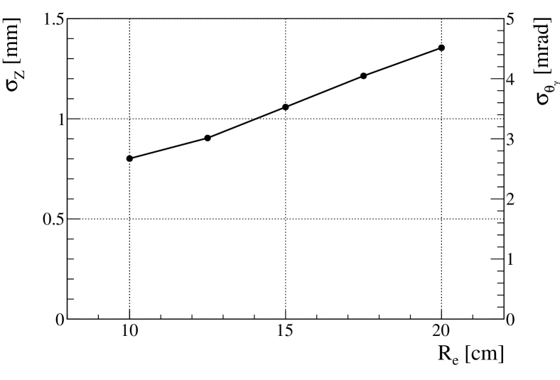
Due to the back-propagation of the track from the measured points to the target, and positron angular uncertainties at the inner layer of the spectrometer also translate into vertex position uncertainties at the target, which increase with the radius of the inner tracking layer. In this respect, it is crucial to have this first layer as close as possible to the target. These effects are illustrated in Tab. 3, where different scenarios are considered for cm, and in Fig. 4, where the dependence on is shown, as an example, for the vertex resolution in the coordinate. We assumed here the tracking resolutions expected for the MEG-II drift chamber, the MS due to Helium and a 25m Kapton foil just in front of the inner tracking layer, a magnetic field of 1 T, tracks emitted in the acceptance and target configuration of MEG-II and a photon detector placed at cm.
| Material | Thickness [m] | Resolutions | ||
|---|---|---|---|---|
| [mrad] | [mrad] | [keV] | ||
| Beryllium | 85 | 2.6 | 2.8 | 20 |
| Polyethylene | 128 | 2.7 | 2.8 | 20 |
| Scintillator (PVT) | 125 | 2.8 | 3.2 | 20 |
| Conditions | Resolutions | ||
|---|---|---|---|
| [mrad] | [mrad] | [keV] | |
| Pure Helium + 25 m Kapton wall | 6.0 3.3 | 4.5 3.3 | 100 |
| Helium:CO2 (90:10) | 6.0 3.2 | 4.6 3.4 | 100 |
| Helium:C4H10 (85:15) | 6.6 4.7 | 5.5 3.9 | 100 |
With the photon conversion technique, the photon conversion point can be measured very precisely, essentially with the single hit resolution of the tracker (m for a gaseous detector), with a first layer placed just behind the converter. As a consequence, the photon angle resolution is completely dominated by the positron vertex resolution. With calorimetry, the detector and readout granularity of the entrance surface determines the resolution, but we can generally say that a sub-mm level can be reasonably reached, giving mrad contributions to and when the detector is placed at a few dozens of cm from the target (60 cm in MEG and MEG-II).
It must be noticed that an absolute calibration of is very difficult to be obtained, resulting in a systematic uncertainty of a few mrad. As an example, in the MEG configuration, the 500 m accuracy obtained for the target position along its normal direction translates into an uncertainty mrad on . Hence, quoting angular resolutions at the mrad level is subject to the non-trivial ability of aligning the target with m accuracy.
4.5 Relative time
A resolution of 120 ps was obtained in MEG with scintillation detectors, and a 80 ps resolution is expected for MEG-II.
The positron time resolution of ps foreseen for MEG-II might be probably improved with the incremental progress of the technologies. It is important to stress here that the positron time is usually measured at the end of the spectrometer, and the time of flight from the target to the timing detector needs to be subtracted. If there are long segments of the positron path which are untracked, the extrapolated track length can fluctuate significantly due to MS and in the crossed materials. In MEG, the track length uncertainty ( ps) turned out to be the largest contribution to the resolution, due to the long untracked path ( m) from the last reconstructed hit to the positron timing detector. In MEG-II this issue will be solved, thanks to the 2 m-long drift chamber, which largely reduces the untracked segments of the positron trajectory with respect to MEG. Future designs should keep in mind this lesson, and this aspect could be critical for silicon detectors, which would track only a small portion of the positron trajectory.
For photons, if the conversion technique is adopted, a further complication arises. As far as only one conversion layer is foreseen, one can place thick scintillators at some distance from the converter, in such a way that either the electron or the positron reaches this detector. On the other hand, in order to stack multiple layers, a layer of active material just behind the converter should provide the required timing resolution. A thick layer (few mm) of plastic scintillators would deteriorate unacceptably the resolution, and thin scintillating fibers (few 100 m) cannot provide a resolution below a few 100 ps and efficiencies above 90% atar . Hence, a technological breakthrough is needed here, and a novel idea will be proposed in Sec. 5. For calorimetry, performances comparable or better than the MEG-II ones could be easily reached, considering the light yield and decay time of the state-of-the-art scintillators.
4.6 Summary
Tab. 4 shows a summary of the limiting factors for the efficiency and resolutions of future searches. We stress again that, with the only exception of the tracking resolutions, these factors come from experimental conditions which are quite independent of the specific detector design, and only marginally dependent on the intrinsic resolutions of the detectors. It means that, even if the detector performances could be arbitrarily improved, most of these factors would remain unchanged. Hence, a radically new experimental approach would be needed to bring the resolutions on the discriminating variables significantly below these limits.
| Typical figure | Comments | ||
| Calorimetry | Conversion | ||
| Efficiency | |||
| Material budget | 0.5 0.9 | – | magnet coil |
| Pair production | – | 0.02 0.04 | 0.05 0.1 |
| Minimum energies | – | 0.8 | MeV |
| Photon Energy Resolution | |||
| Energy loss | – | 250 800 keV | 0.05 0.1 |
| Photon Statistics & segmentation | 800 keV | – | |
| Positron Energy Resolution | |||
| Energy loss | 15 keV | ||
| Tracking & MS | 100 keV | ||
| Relative Angle Resolution | |||
| MS on target | 2.6 / 2.8 mrad ( / ) | ||
| MS on gas & walls | 3.3 / 3.3 mrad ( / ) | cm, cm, B = 1 T | |
| Tracking | 6.0 / 4.5 mrad ( / ) | ||
| Alignment | mrad | 100 m target alignment | |
5 Photon reconstruction perspectives
In this Section we discuss two possible realistic photon detectors for searches. We will consider a calorimetric approach with LaBr3(Ce) crystals and a pair production approach with one or more layers of conversion material.
5.1 Calorimetry
A homogeneous scintillation detector is placed out of the positron tracking volume and the magnetic field, and provides the , the photon conversion point, and the photon time measurements. With their high light yield and fast response, LaBr3(Ce) crystals are a good candidates. Thanks to its high density (5.08 g/cm3), a 20 cm long crystal with 13 cm diameter would contain the electromagnetic shower up to 100 MeV. Silicon photon detectors like MPPCs could be coupled to the crystal, in such a way that a good coverage is guaranteed ( of the crystal surface considering the inactive areas of the single detector).
We performed a set of GEANT4 simulations, which were validated against data obtained with a 3 inch (diameter) 3 inch (length) LaBr3(Ce) crystal, irradiated with different sources, and in particular 9 MeV rays from neutrons captured on Nickel, and instrumented with PMTs and MPPCs in order to characterize both the crystal and photon detector response papa . The simulation includes the MPPC response, a full electronics chain and the reconstruction algorithms. Different geometries, sensors and analysis algorithms have been investigated. In the end, a and a time resolution ps are predicted at the decay energy. Tab. 5 summarizes the performance of this solution.
| Performance | Source | |
|---|---|---|
| Acceptance | 70% | |
| Efficiency | 60% | |
| Photon Energy Resolution | Energy loss | |
| Photon Angle Resolution | 4.5 / 2.7 mrad ( / ) | Positron vertex resolution |
| Photon Time | 30 ps | |
5.2 Pair production
A basic design for a experiment adopting the photon conversion technique would consist of tracking detectors interleaved with one or more thin conversion layers. The design of the detector is also constrained by the requirement that an extended tracker for 52.8 MeV positron and tracking devices for the low-momentum photon-conversion products should coexist in the same magnetic field.
According to our results (see Sec. 4.2), the resolution is expected to be dominated by the fluctuations of the energy loss in the converter, when its thickness is greater than 0.1 . For smaller values, the tracking of the pair can be relevant, considering that previous studies caltech ; snowmass point toward a 200-300 keV contribution.
Moreover, it should be noticed that, if a single layer is used, its size and the magnetic field can be optimized in such a way that the positron from the muon decay and at least one of the tracks in the pair reach the outer radius of the detector, where fast detectors for timing could be placed. If multiple layers are foreseen, the conversion layer itself should include an active component, able to measure the timing with the required resolution (but scintillating fibers cannot provide the required performances).
A possible solution is given by a new generation of silicon detectors, with extremely good time resolution. An R&D activity is ongoing (TT-PET project TT-PET ; TT-PET-test ) to realize a thin monolithic detector (100-300 um) in a Si-Ge Bi-CMOS process, that contains both the silicon sensor and the front-end electronics, featuring less than 100 ps time resolution for minimum ionizing particles. A dedicated design could be adopted in the application, by stacking multiple detector layers in order to improve the resolution accordingly.
The additional low-Z material of the detector behind the converter is expected to deteriorate the resolution without contributing significantly to the conversion efficiency. According to our simulations, a single layer with the specifications in TT-PET-test (100 m silicon on top of 50 m Kapton) would give a negligible contribution to the resolution. For a 4-layer system, which would give a 50 ps resolution, comparable with the timing performances of the MEG-II LXe calorimeter, this contribution would be keV, i.e. of the same order of the energy loss fluctuations for a 0.05 Lead converter.
It is also worth mentioning that, if the converter layer itself would be active and could provide some information about the energy deposit, it could be used to improve the resolution.
| Performance | Source | |
|---|---|---|
| Acceptance | 70% | |
| Conversion Efficiency | 2.2% | |
| MeV Selection Efficiency | 80% | |
| Photon Energy Resolution | Energy loss tracking | |
| Photon Angle Resolution | 4.5 / 2.7 mrad ( / ) | Positron vertex resolution |
| Photon Time | 50 ps | |
Based on the results of Sec. 4, Tab. 6 shows the expected photon reconstruction performances for this design. We assume:
-
•
one passive conversion layer, 0.05 Lead, covering in and 60 cm in , and placed at cm;
-
•
scintillating tiles at the end of the trajectory of conversion pairs and positrons from muons, providing a time resolution of 50 ps;
-
•
a tracking system providing an vertex resolution which contributes negligibly to the photon angle uncertainty (with respect to the contribution of the positron vertex reconstruction) and to the resolution (with respect to the fluctuations of the energy loss in the converter).
If multiple conversion layers are present and timing is provided by the TT-PET detectors, the 50 ps resolution can be preserved but the photon energy resolution deteriorates as estimated above.
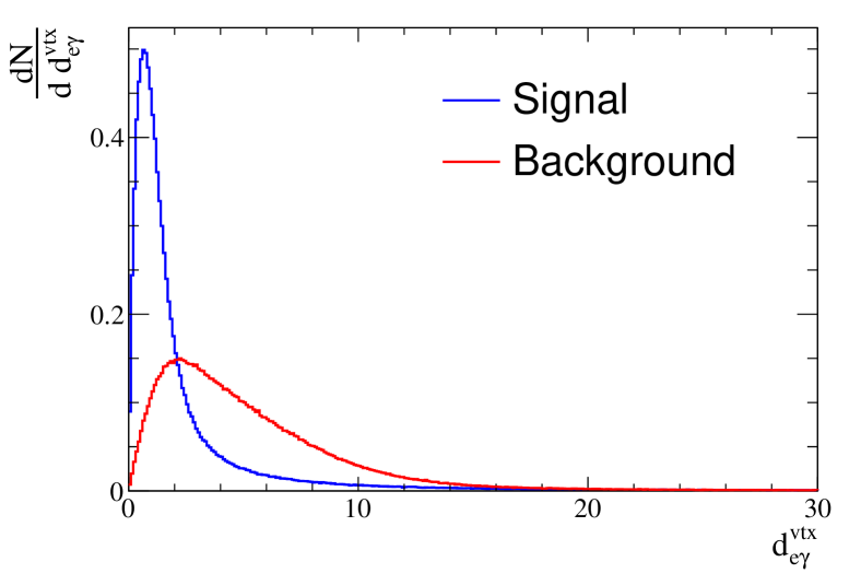
Beside providing better resolutions with respect to calorimetry, the photon conversion technique also provides a measurement of the photon direction, from the combination of the reconstructed directions of the pair, independently of the positron reconstruction. The resulting angular resolution, deteriorated by the MS in the converter, is mrad with Lead, and hence cannot compete with the one obtained from the combination of the positron vertex and photon conversion point. Nonetheless, this additional information can be used to reduce the accidental background. In Fig. 5 we show the distribution of the normalized distance defined as:
| (4) |
where ( , ) and ( , ) are the coordinates on the target of the vertex obtained in two ways, one by propagating the positron track back to the target and the other by using the direction of the pair. The uncertainties ( and ) of the back-propagation are used, since they largely dominate over the positron vertex resolutions. The expected distributions for signal and accidental background events with the photon coming from the target (assuming the same beam profile used in MEG) are shown in Fig. 5, for a 0.05 Lead converted at cm, a slanted target and the acceptance defined in Sec. 4.4. In this scenario, the optimal ratio of signal to square root of background is obtained for , which removes 91% of background events with 52% signal efficiency. Similarly, background produced by positron AIF occurring far from the target would be easily removed without any significant loss of signal efficiency. However the average background rejection capability is lower if multiple conversion layers are used, because the layers after the first one have a larger and hence the resolution of the back-projection to the target is worse for photons converting there.
6 Positron reconstruction perspectives
We consider a positron detector, composed of two sectors: a vertex detector for a precise determination of the muon decay point and the positron angles, and an extended tracker for the measurement of the positron momentum.
6.1 Vertex detector
As already discussed, a silicon detector would not be competitive with a gaseous detector as an extended tracker. Nonetheless, we can still consider the possibility of having two layers of silicon detectors for vertexing. Silicon pixels would give a very good vertex resolution, thanks to the very precise determination of both the azimuthal and the longitudinal coordinate (m). In practice, the vertex and angle resolution would be completely dominated by the MS in this detector. As a consequence, the extended tracker would be only useful for the determination of .
As an alternative, one could consider a time projection chamber (TPC) with a very light (helium-based) gas mixture. The single hit resolution of such a device would be limited by the diffusion of the drifting electrons, but a large number of hits would be available. Gaseous electron multiplier (GEM) foils or Micromegas could be used to generate the electron avalanche, inducing signals on readout pads and allowing the TPC to be operated in continuous mode (no gating) even in presence of a very high track rate gem_tpc .
We performed simulations with the GARFIELD software garfield , assuming a He:CO2 (90:10) gas mixture, a 0.5 T magnetic field and a 1 kV/cm electric field. We assume the readout to be performed with very high granularity, as in the GEMPIX gempix and InGrid ingrid projects, so that the single ionization clusters are detected and the space resolution is dominated by the diffusion of the drifting electrons. For a given drift distance , a resolution of is found in the azimuthal (longitudinal) coordinate, with hits per track. On the other hand, at a very high rate, the use of such a device would be limited by both the rate capability of the multiplication stage and the space charge accumulated in the drift region due to the primary ionization itself.
6.2 Extended tracker
The basic option for the extended tracker is a drift chamber, with stereo wires for the measurement of the longitudinal position. The MEG-II drift chamber can be used as a benchmark for the material budget and the single hit resolution.
On the other hand, the high track rate in the inner layers is expected to produce visible aging effects at the beam rate expected in MEG-II meg2 . It could make a TPC the only choice for a gaseous extended tracker at higher beam rates. The detector geometry would be strongly constrained, because a very long TPC ( 1 m drift distance) could not provide acceptable resolutions due to the electron diffusion. As an alternative, in the early stages of the MEG upgrade project, a 2 m long radial TPC was proposed, with a He:CO2:C2H6 (70:10:20) gas mixture. The radial design implies some technical difficulties connected to the drift of the electrons orthogonally to the magnetic field. First, their diffusion is not suppressed by the magnetic field as in a longitudinal TPC. Second, the curved trajectory of the drifting positrons need to be accounted in the reconstruction stages. If these problems can be overcome with a proper tuning of the gas mixture composition, an accurate knowledge of the magnetic field and a detailed calibration of the drift trajectories, a resolution of in the radial and azimuthal coordinates could be achieved meg2 , with drift distances not exceeding 10 cm.
7 Target optimization
The target thickness represents one of the most stringent limitations to the achievable angular resolution. In order to use thinner targets, two options can be investigated.
-
1.
If the muon momentum can be significantly reduced, without reducing the beam intensity and preserving a good momentum bite, the distribution of the muon decay depth in the target (i.e. the width of the Bragg peak) is reduced accordingly. A thinner target could be used, improving the angular resolution without affecting , and .
-
2.
The target could be replaced by multiple thinner targets. A tentative design consists of a V-shaped target, made of two planes forming a angle. The problem with such an approach is that a relevant fraction of muons would decay in the gas within the two targets: signal events from such muons could not be identified, contributing only to the accidental background. As an example, two Beryllium targets of 40 m thickness each would provide 80% stopping efficiency on target, while 13% of muons would decay in the gas between the two target sections. The advantage in terms of angular resolutions would be far too small to compensate this inefficiency. The use of multiple targets can nonetheless help to reduce the background, when the photon conversion approach is used to reconstruct the photon direction. If, for instance, the single target foil is replaced by two staggered foils, each illuminated by half the beam spot, and with sufficient separation in space, the back-propagation of the pair can be used to identify the foil where the photon has been produced, and check if it is the same of the positron. In this case, the accidental background is effectively reduced by a factor of two. More generally, spreading the beam over a larger surface makes more effective the background rejection based on the goodness of the electron-photon vertex.
8 Sensitivity reach
In this Section we give an estimate of the sensitivity reach of a search based on the technologies described above. At first, we consider a basic design based on the photon conversion technique, with a single conversion layer, an inner vertex detector (silicon pixels or a TPC) and a 200 cm long extended tracker (a drift chamber or a TPC) which would serve as a positron and a positron-electron pair spectrometer.
The inclusion of multiple conversion layers would be an interesting improvement to this design. It can be made without any loss in the timing performances only if timing is provided by fast silicon detectors at the conversion layer.
We finally consider a calorimetric approach for the photon reconstruction, while leaving the positron reconstruction unchanged.
In both cases, we neglect the difficulties connected to the reconstruction of signal events in a crowded environment with positron tracks from multiple Michel muon decays.
8.1 A design with photon conversion
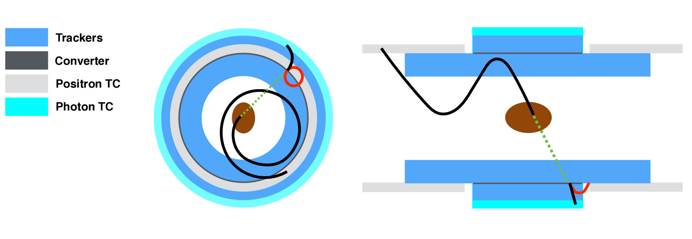
In Fig. 6 we show a sketch of a detector based on the photon conversion technique, with two different options for the inner vertex detector and a typical signal event. A similar design was recently proposed in snowmass .
In this design, a target identical to the one of MEG-II is surrounded by a positron tracker extending from to cm. with a length of 200 cm. It can be a drift chamber or a radial TPC. As in MEG and MEG-II, plastic scintillators (positron timing counters) are placed behind it, in order to measure the positron track timing.
At cm, a 60 cm long Lead conversion layer is placed, with a thickness. The longitudinal extent of the conversion layer defines the acceptance of the detector, .
Externally, a 84 cm long drift chamber or radial TPC is used as an electron-positron pair spectrometer. This chamber extends up to cm, where plastic scintillators (photon timing counters) are placed.
Optionally, a small TPC or a two-layer silicon vertex detector can be considered. Both detectors are 40 cm long. The TPC has an inner radius of 10 cm and an outer radius of 20 cm. The first silicon layer is placed at a radius of 10 cm.
Everything is immersed in a graded magnetic field similar to the MEG one, such that, for events within the acceptance defined above, the signal positron curls before reaching the converter layer and finally reaches the positron timing counters, while at least one of the tracks from the photon conversion goes through the whole pair spectrometer and reaches the photon timing counters.
We estimated the expected performances of such a detector. For simplicity, we rely on the results shown in Tab. 6 for the photon reconstruction, although they are obtained for a uniform magnetic field. For the positron angle and momentum reconstruction in the tracker we assume the performances of the MEG-II drift chamber, with a 90% reconstruction efficiency, while for the vertex resolution with an inner tracker we assume two different scenarios. In the first, conservative one, the only improvement comes from having the first measured point which is closer to the target, while the momentum and angular resolutions are still dominated by the extended tracker, and the angular resolution is deteriorated by the presence of the inner wall of the TPC or the inner layer of the silicon vertex tracker. In the second, optimistic one, the vertex detector makes the tracking contribution to the angular resolution negligible. This resolution is then completely determined by material effects before and inside the first layer of the inner vertex detector. A summary of the expected performances can be found in Tab. 7 and 8. It is evident that a silicon vertex detector cannot help, because the MS in the first layer of such a detector negates the advantage of having a very good determination of the track angle between the first and the subsequent layers.
| Observable | one photon | photon |
|---|---|---|
| conversion layer | calorimeter | |
| [ps] | 60 | 50 |
| [keV] | 100 | 100 |
| [keV] | 320 | 850 |
| Efficiency [%] | 1.2 | 42 |
| [mrad] | [mrad] | |
|---|---|---|
| None | 7.3 | 6.2 |
| TPC | 3.5 (6.1) | 3.8 (4.8) |
| Silicon | 8.0 (6.3) | 7.4 (6.9) |
We also considered a simpler design, with similar radial dimensions, where the magnetic field is reduced to 0.5 T and the conversion layer covers only a portion () of the azimuthal angular range. In this design, signal positrons reach the pair spectrometer, which also acts as an extended tracker, without hitting the conversion layer if the corresponding photon does. Finally, the positron reaches the same counters used for photon timing. Simulations show that such a design, similar to the one proposed in caltech , implies a large degradation of the momentum resolution. While it could be still suitable for a beam rate /s, this design would not fit a larger rate and, as acknowledged in caltech , the optimal working point would be even lower in a scenario where multiple conversion layers are used.
8.2 A design with calorimetry
A experiment based on calorimetry could have a design very similar to the one above for the central part of the detector, but the external pair tracker would be replaced by a scintillation detector placed outside of the magnet. With LaBr3(Ce) crystals, the calorimeter could be about 20 cm deep and the performance summarized in Tab. 7 and 8 could be reached. Here we assume that the photon conversion point can be still determined with a negligible resolution compared to the positron vertex resolution.
8.3 Sensitivity estimates
We consider here 100 weeks of data taking (3 to 4 years at PSI), with muon rates from to muons per second. We define a different signal region for each scenario, in such a way that, according to the resolutions estimated above, the efficiency for the signal to be inside that region is always 70%. We then assume that a counting analysis is performed on the events falling within this region.
Formulas in kuno-okada allow to estimate the background rate, by using as an input the measured photon rate in the MEG calorimeter, linearly scaled with the beam rate. Considering that the geometry in the central region of the detector is very similar to the MEG one, this approach takes into account reliably the rate of AIF photons, which would be otherwise very difficult to extract from simulations, given the extremely low probability of this process per single muon decay.
When the photon conversion technique is adopted, we also assume a background rejection performed by requiring a good electron-photon vertex as explained in Sec. 5. The efficiency and background rejection capabilities of this approach are determined in each scenario according to the expected resolutions.
Finally, we extract the expected sensitivity of the experiment according to a frequentistic approach feldman-cousins .
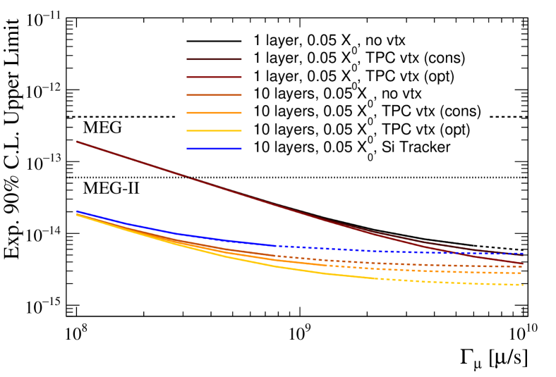
Figures 7 and 8 show the expected sensitivity to the decay as a function of the beam intensity in different scenarios.
Among them, we also considered the possibility of multiple conversion layers. In this case, we introduce fast silicon detectors for timing, with several layers to reach a 50 ps time resolution. The photon energy resolution is degraded accordingly (see Sec. 5).
In Fig. 7 we compare different designs based on the photon conversion approach. Apart from the obvious advantage of having multiple layers, it should be noticed that a vertex detector would be only useful at very large beam rates. We do not consider the silicon vertex detector option because, according to Tab. 8, it would not significantly improve the expected performances. We consider instead a scenario where the extended tracker is made of silicon detectors, with the performances presented in caltech , which could be the only available solution if aging effects make impossible to operate a gaseous detector.
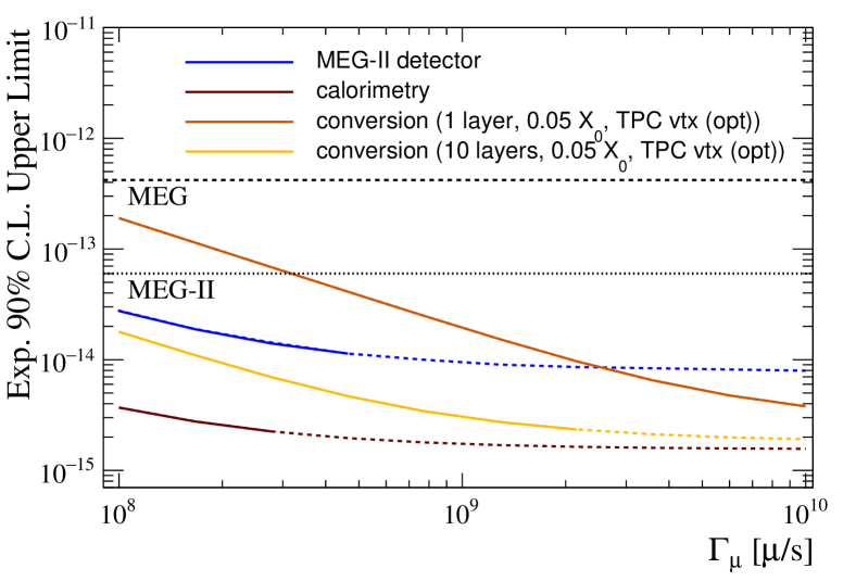
In Fig. 8 we compare the performances of an experiment with calorimetry with the performances of the best photon conversion designs. We also show for comparison how the MEG-II detector would perform at the same beam rates. Calorimetry is definitively advantageous at low beam rate, as expected, but there is a wide range of beam intensity where this approach would be limited by the background, while the photon conversion approach would not give yet a better sensitivity, unless a very large detector with many conversion layers is built.
In conclusion, a limit seems to be within reach with a muons per second stopping rate, while a further increase of the beam rate up to would only improve the sensitivity by a factor of 2.
9 Conclusions
Efforts are ongoing to develop muon beam-lines with intensities near and possibly approaching muons per second, to be used for a future generation of cLFV searches in muon decays.The HiMB project at PSI aims to reach muons per second in the next decade, while the MuSIC project at RCNP (Japan) is experimenting different approaches to increase the muon yield per unit of power of the primary proton beam. The FNAL project PIP-II could be also competitive in this field.
In this paper we investigated the experimental factors that will limit the sensitivity reach of future experiments searching for the decay with a continuous muon beam at high intensity.
The most relevant issue is the choice of the photon detection technique between calorimetry and the reconstruction of the pair from photon conversion in a thin layer of high-Z material, being favored the former by the much higher detection efficiency and the latter by the far superior resolutions, along with the possibility of rejecting accidental background events by reconstructing the photon-positron vertex.
On the positron side, tracking with gaseous detectors would ideally provide the best possible resolutions, which would be eventually limited by the multiple Coulomb scattering experienced by the particle in the target and in the material in front of the tracker. On the other hand, the high occupancy in the inner part of the tracking system could severely limit the possibility of using gaseous detectors. A significant deterioration of the overall sensitivity (more than a factor 2) is expected if a silicon tracker has to be used for this reason.
Sensitivity projections show that a 3-year run with an accelerator delivering around muons per second could allow to reach a sensitivity of a few (expected 90% upper limit on the BR), with poor perspectives of going below even with muons per second. Below muons per second, the calorimetric approach needs to be used in order to reach this target. If a muon beam rate exceeding muons per second is available, the much cheaper photon conversion option would be recommended and would provide similar sensitivities.
The sensitivity would be eventually limited by the fluctuation of the interaction of the particles with the detector materials: this indicates that a further step forward in the search for would require a radical rethinking of the experimental concept.
10 Acknowledgments
This paper is dedicated to the memory of our colleague Giancarlo Piredda, whose inspiration was invaluable in the early stages of this work. We are also grateful to all our MEG and MEG-II colleagues for valuable discussions.
References
- (1) A. M. Baldini et al. [MEG Collaboration], Eur. Phys. J. C 76 (2016) no.8, 434.
- (2) M. Lindner, M. Platscher and F. S. Queiroz, arXiv:1610.06587 [hep-ph].
- (3) P. R. Kettle, contribution to Future Muon Sources 2015, University of Huddersfield, United Kinkdom; A. Knecht, contribution to SWHEPPS2016, Unterägeri, Switzerland; F. Berg et al., Phys. Rev. Accel. Beams 19 (2016) no.2, 024701
- (4) S. Cook et al., Phys. Rev. Accel. Beams 20 (2017) no.3, 030101.
- (5) V. Lebedev, ed. [PIP-II Collaboration], FERMILAB-DESIGN-2015-01.
- (6) Y. Kuno and Y. Okada, Rev. Mod. Phys. 73 (2001) 151.
- (7) R. H. Bernstein and P. S. Cooper, Phys. Rept. 532 (2013) 27.
- (8) A. M. Baldini et al. [MEG Collaboration], Eur. Phys. J. C 76 (2016) no.3, 108.
- (9) F. DeJongh, FERMILAB-TM-2292-E.
- (10) J. Adam et al. [MEG Collaboration], Eur. Phys. J. C 73 (2013) no.4, 2365.
- (11) M. L. Brooks et al. [MEGA Collaboration], Phys. Rev. Lett. 83 (1999) 1521.
- (12) A. M. Baldini et al., arXiv:1301.7225 [physics.ins-det].
- (13) J. Albrecht et al. [Intensity Frontier Charged Lepton Working Group], arXiv:1311.5278 [hep-ex].
- (14) C. h. Cheng, B. Echenard and D. G. Hitlin, arXiv:1309.7679 [physics.ins-det].
- (15) D. Hitlin, private communication.
- (16) S. Agostinelli et al. [GEANT4 Collaboration], Nucl. Instrum. Meth. A 506 (2003) 250.
- (17) G. Punzi, eConf C 030908 (2003) MODT002.
- (18) N. Berger et al., Nucl. Instrum. Meth. A 732 (2013) 61
- (19) I. Peric et al., Nucl. Instrum. Meth. A 731 (2013) 131.
- (20) A. M. Baldini et al., JINST 11 (2016) no. 07, P07011
- (21) A. Papa, G. Cavoto and E. Ripiccini, Nucl. Phys. Proc. Suppl. 248-250 (2014) 121.
- (22) A. Papa et al., paper in preparation; A. Papa et al., Nucl. Phys. Proc. Suppl. 248-250 (2014) 115; L. Galli et al., Nucl. Instrum. Meth. A 718 (2013) 48.
- (23) TT-PET project, SNSF grant CRSII2-160808
- (24) M. Benoit et al., JINST 11 (2016) no. 03, P03011
- (25) L. Fabbietti et al., Nucl. Instrum. Meth. A 628 (2011) 204.
- (26) R. Veenhof, Conf. Proc. C 9306149 (1993) 66.
- (27) F. Murtas, JINST 9 (2014) no.01, C01058.
- (28) M. Lupberger et al., PoS TIPP 2014 (2014) 225.
- (29) G. J. Feldman and R. D. Cousins, Phys. Rev. D 57 (1998) 3873.