Phase sensitive photonic flash
Abstract
We theoretically propose a photonic flash based on a linearly coupled cavity system. Via driving the two side cavities by external fields, it forms a cyclic energy-level diagram and therefore the phase difference between the driving fields acts as a controller of the steady state due to the quantum interference effect. In the optical trimer structure, we show that the perfect photonic flash can be realized in the situation of resonant driving. The perfect photonic flash scheme is furthermore generalized to multiple coupled cavity system, where the cavities with odd and even number turn bright and dark alternatively. Our proposal may be applied in the designing of quantum neon and realizing a controllable photonic localization.
1 Center for Quantum Sciences and School of Physics and Center for Advanced Optoelectronic Functional Materials Research and Key Laboratory for UV Light-Emitting Materials and Technology of Ministry of Education, Northeast Normal University, Changchun 130024, China
2 Beijing Computational Science Research Center, Beijing 100094, China
\email∗wangzh761@nenu.edu.cn
(230.4555) Coupled resonators; (270.5580) Quantum electrodynamics; (270.5585) Quantum information and processing.
References
- [1] M. Bayindir, B. Temelkuran, and E. Ozbay, ``Propagation of photons by hopping: A waveguiding mechanism through localized coupled cavities in three-dimensional photonic crystals'', Phys. Rev. B 61, R11855 (2000).
- [2] D. K. Armani, T. J. Kippenberg, S. M. Spillane, and K. J. Vahala, ``Ultra-high-Q toroid microcavity on a chip'', Nature 421, 925 (2003).
- [3] A. Wallraff, D. I. Schuster, A. Blais, L. Frunzio, R.- S. Huang, J. Majer, S. Kumar, S. M. Girvin, and R. J. Schoelkopf, ``Circuit quantum electrodynamics: Coherent coupling of a single photon to a Cooper pair box'', Nature 431 162 (2004).
- [4] A. Blais, R.-Shou Huang, A. Wallraff, S. M. Girvin, and R. J. Schoelkopf, ``Cavity quantum electrodynamics for superconducting electrical circuits: An architecture for quantum computation'', Phys. Rev. A 69, 062320 (2004).
- [5] L. Zhou, Z. R. Gong, Y.-x. Liu, C. P. Sun, and F. Nori, ``Controllable scattering of a single photon inside a one-dimensional resonator waveguide'', Phys. Rev. Lett. 101, 100501 (2008).
- [6] L. Zhou, L.-P. Yang, Y. Li, and C. P. Sun, ``Quantum routing of single photons with a cyclic three-level system'', Phys. Rev. Lett. 111, 103604 (2013).
- [7] Z. H. Wang, L. Zhou, Y. Li, and C. P. Sun, ``Controllable single-photon frequency converter via a one-dimensional waveguide'', Phys. Rev. A 89, 053813 (2014).
- [8] A. Zheng, G. Zhang, L. Gui, and J. Liu, ``Single-photon frequency conversion and multi-mode entanglement via constructive interference on Sagnac loop'', Laser Phys. 25, 065201 (2015).
- [9] W.-B. Yan, J.-F. Huang, and H. Fan, ``Tunable single-photon frequency conversion in a Sagnac interferometer'', Sci. Rep. 3, 3555 (2013).
- [10] F. Nissen, S. Schmidt, M. Biondi, G. Blatter, H. E. Tureci, and J. Keeling, ``Nonequilibrium dynamics of coupled qubit-cavity arrays'', Phys. Rev. Lett. 108, 233603 (2012).
- [11] A. Le Boite, G. Orso, and C. Ciuti, ``Steady-state phases and tunneling-induced instabilities in the driven dissipative Bose-Hubbard model'', Phys. Rev. Lett. 110, 233601 (2013).
- [12] J. Jin, D. Rossini, R. Fazio, M. Leib, and M. J. Hartmann, ``Photon solid phases in driven arrays of nonlinearly coupled cavities'', Phys. Rev. Lett. 110, 163605 (2013).
- [13] J. Raftery, D. Sadri, S. Schmidt, H. E. Tureci, and A. A. Houck, ``Observation of a dissipation-induced classical to quantum transition'', Phys. Rev. X 4, 031043 (2014).
- [14] J. Jin, A. Biella, O. Viyuela, L. Mazza, J. Keeling, R. Fazio, and D. Rossini, ``Cluster mean-field approach to the steady-state phase diagram of dissipative spin systems'', Phys. Rev. X 6, 031011 (2016).
- [15] J. J. Mendoza-Arenas, S. R. Clark, S. Felicetti, G. Romero, E. Solano, D. G. Angelakis, and D. Jaksch, ``Beyond mean-field bistability in driven-dissipative lattices: Bunching-antibunching transition and quantum simulation'', Phys. Rev. A 93, 023821 (2016).
- [16] C. Noh and D. G Angelakis, ``Quantum simulations and many-body physics with light'', Rep. Prog. Phys. 80, 016401 (2017).
- [17] S. Schmidt and J. Koch, ``Circuit QED lattices: towards quantum simulation with superconducting circuits'', Ann. Phys. (Amsterdam) 525, 395 (2013).
- [18] Z. H. Wang, X.-W. Xu, and Y. Li, ``Partially dark optical molecule via phase control'', Phys. Rev. A 95, 013815 (2017).
- [19] Y.-X. Liu, J. Q. You, L. F. Wei, C. P. Sun, and F. Nori, ``Optical selection rules and phase-dependent adiabatic state control in a superconducting quantum circuit'', Phys. Rev. Lett. 95, 087001 (2005).
- [20] W. Z. Jia and L. F. Wei, ``Gains without inversion in quantum systems with broken parities'', Phys. Rev. A 82, 013808 (2010).
- [21] M. Shapiro, E. Frishman, and P. Brumer, ``Coherently controlled asymmetric synthesis with achiral light'', Phys. Rev. Lett. 84, 1669 (2000).
- [22] P. Kral and M. Shapiro, ``Cyclic population transfer in quantum systems with broken symmetry'', Phys. Rev. Lett. 87, 183002 (2001).
- [23] P. Kral, I. Thanopulos, M. Shapiro, and D. Cohen, ``Two-step enantio-selective optical switch'', Phys. Rev. Lett. 90, 033001 (2003).
- [24] Y. Li, C. Bruder, and C. P. Sun, ``Generalized Stern-Gerlach effect for chiral molecules'', Phys. Rev. Lett. 99, 130403 (2007).
- [25] J. Tang, W. Geng, and X. Xu, ``Quantum interference induced photon blockade in a coupled single quantum dot-cavity system'', Sci. Rep. 5, 9252 (2015).
- [26] Y. Liu and D. L. Zhou, ``Quantum state transfer along a ring with time-reversal asymmetry'', Phys. Rev. A 91, 052318 (2015).
- [27] W. Z. Jia, L. F. Wei, Y. Li, and Y.-x. Liu, ``Phase-dependent optical response properties in an optomechanical system by coherently driving the mechanical resonator', Phys. Rev. A 91, 043843 (2015).
- [28] X. W. Xu and Y. J. Li, ``Antibunching photons in a cavity coupled to an optomechanical system'', J. Phys. B 46, 035502 (2013).
- [29] P. W. Anderson, ``Absence of diffusion in certain random lattices'', Phys. Rev. 109, 1492 (1958).
- [30] A. Pal and D. A. Huse, ``Many-body localization phase transition'', Phys. Rev. B 82, 174411 (2010).
1 Introduction
Coherent photonic control and designing photonic devices are of potential application in quantum information processing, and the coupled cavity array system provides an ideal platform for achieving such tasks.
In the coupled cavity array system, which can be realized by the photonic crystal [1], toroid micocavity [2] as well as superconductive transmission line [3, 4], the coherent photonic control has invoked a lot of attentions. In the ideal situation, where the decay of the cavities is neglected, kinds of single-photon devices have been theoretically proposed within the scattering frame, such as quantum transistor [5], quantum router [6] and quantum frequency converter [7, 8, 9]. On the other hand, in the coupled cavity array with loss, it has been shown that the non-equilibrium quantum phase transition, which is related to the steady state, may occur in some nonlinear system when the driving and dissipation are both present [10, 11, 12, 14, 13, 15]. Therefore, it supplies a photonic platform to simulate many body phenomenon in condensed matter physics [16, 17]. Naturally, the steady state in the coupled cavity array with only linear interaction deserves more exploration.
In this paper, by investigating the photonic distribution of steady state in a linearly coupled cavity array system, we propose a scheme to realize photonic flash. We here use the phrase ``photonic flash'' to refer that when some of cavities in the coupled cavity array are completely dark, the other ones are completely bright, and the bright and dark cavities can be exchanged by tunning the system parameters appropriately. In our scheme, the two side cavities are driven by a pair of external fields, we will show that the phase difference between the driving fields acts as an ideal controller for the steady state, which stems from the quantum interference effect among the multiple transition channels. As a simple example, we sketch the realization of dark cavity in an optical trimer, and show that we can construct a perfect photonic flash under the situations (i) the central cavity of the trimer is lossless and (ii) the two side cavities are driven resonantly. Generalizing the scheme to an array of multiple coupled cavities, we show that the cavities with odd and even number will be bright and dark alternatively by adjusting the phase difference. Therefore, we design a scalable photonic flash based on linear coupled cavity array system. Instead of controlling each cavity individually, we here only drive the two side cavities, regardless of the total number of the cavities, and therefore is beneficial to avoiding the difficulties of addressing. As the potential application in the designing of photonic device and quantum simulation based on our proposal, we also give a simple remark on the realizing of quantum neon and controllable photonic localization.
The rest of the paper is organized as follows. In Sec. 2, we present the model of an optical trimer and the steady state values. In Sec. 3, we discuss the condition to realize perfect photonic flash in the trimer structure and generalize it to multi-coupled-cavity system in Sec. 4. At last, we discuss the effect of quantum noise and give a brief remark and conclusion in Sec. 5.
2 Model of optical trimer
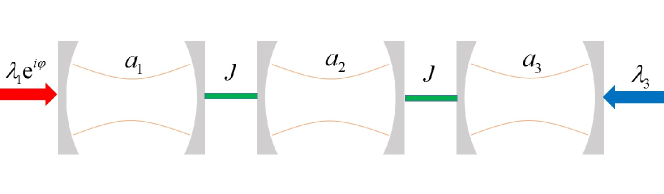
The optical trimer system in our consideration is sketched in Fig. 1, in which the cavity are coupled to the cavity simultaneously and are driven by classical fields with the same frequency . In the rotating frame with respect to the frequency of the driving fields, the Hamiltonian can be written as (here and after )
| (1) | |||||
where is the detuning between the th cavity and the driving fields. Here, is the resonant frequency of cavity , which is described by the annihilation operator . is nearest inter-cavity coupling strength. and are the driving strengths to cavity and , respectively. is the phase difference between the two driving fields, which will play an important role in the controlling of photons. Without loss of generality, we assume that all the parameters are real.
Assuming the decay rate of the th cavity is , the dynamics of the system is determined by the Heisenberg-Langevin equation (neglecting the fluctuations)
| (2) |
where , and the matrix is
| (3) |
Then, the steady-state values of the system are immediately given by
| (4a) | |||||
| (4c) | |||||
where . Therefore, the steady state property is sensitively dependent on the phase difference between the two driving fields. This phase dependence mechanism is similar to those in optical molecule (dimer) system [18], superconducting artificial [19, 20], chiral molecule [21, 22, 23, 24], cavity-QED system [25, 26] and cavity optomechanical system [27, 28], where the coupling and driving contribute a cyclic energy-level structure.
3 Photonic flash in the trimer
As discussed above, the phase difference is a potential controller for the photonic state in an optical trimer, which supplies us a convenient way to design the coherent optical device, such as photonic flash, utilizing the interference effect. Here, we use the phrase ``photonic flash'' to mean that, by adjusting only the phase difference between the driving fields, we will make one or few of the cavities reaches their vacuum steady state, while the intensity in other cavities reach their maximum values. In other words, we will realize the bright and dark cavities simultaneously, and they can be controllably swapped.
To be explicit, we consider a simple scheme in which . According to the formula in Eqs. (4), the condition for is
| (5) |
and the condition for is
| (6) |
Obviously, the above two equations imply
| (7) |
Furthermore, in the case of , we will obtain that .
Therefore, by appropriately choosing the parameters so that the condition in Eq. (7) is satisfied, we can make any of the cavity dark by tuning the phase difference . Under the condition in Eq. (7), the photonic intensity in each cavity can be expressed in a compact form as
| (8a) | |||||
| (8b) | |||||
| (8c) | |||||
where and
| (9) |
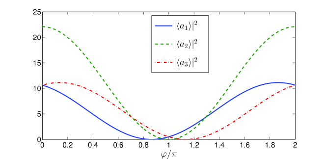
The phase dependence of steady state values in the case of is shown in Fig. 2, where we plot as a function of . It shows that, when , and when . In other words, we can realize the partially dark cavities in the trimer system, which is similar to that in optical molecule or dimer system [18].
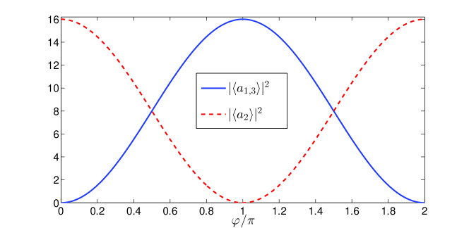
However, as shown in Fig. 2, when any of the cavities is dark with zero average photons in the steady state, the photonic intensity in the other two cavities can not achieve their maximum values. That is, we can not construct a perfect photonic flash. This defect can be overcome by driving the system resonantly, that is , in which situation we need a lossless condition (whose realization will be discussed later) to grantee the validity of Eq. (7). As a result, we will reach and the average photon number become and . In Fig. 3, we plot the curve of the steady values for . Therefore, when , we will have , and , achieving their maximum values. On contrary, by adjusting (or ), the two side cavities in the trimer become completely dark, that is , and the central cavity becomes bright. In Fig. 3, we have chosen the inter-coupling strength as , so that we will reach that the maximum values of , and are equal to each other. In such a way, we have constructed a perfect photonic flash only by tunning the phase difference in an optical trimer system.
4 Generalization to coupled cavity array
The scheme of phase dependent photonic flash can also be naturally generalized to the system of linearly coupled cavities. By driving the st and th cavities classically, the Hamiltonian of the system reads (in the rotating frame)
| (10) |
Motivated by the realization of perfect photonic flash in optical trimer structure, we here assume a resonant driving situation, and that all of the middle cavities are lossless by setting the parameters as and . The Heisenberg-Langevin equation (neglecting the quantum noise) then reads
| (11a) | |||||
| (11b) | |||||
| (11c) | |||||
Firstly, let us consider the situation for odd by assuming , where is an integer. The steady state values can be obtained from Eqs. (11) as
| (12) | |||||
| (13) |
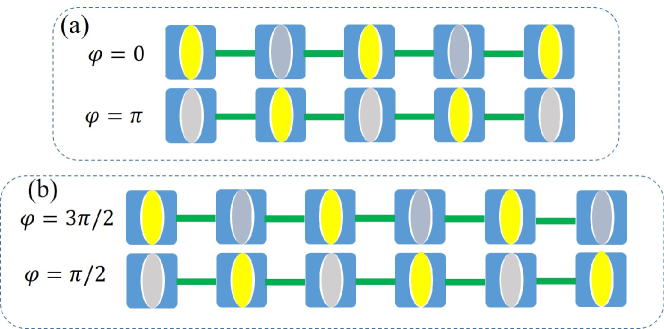
for . It implies that, when , all of the odd number cavities will be completely dark with zero intensity. Meanwhile, the photonic intensity in the even number cavities will achieve their maximums. The opposite event will occur as long as the phase difference satisfies , for which the even number cavities become dark and the odd ones become bright. In Fig. 4(a), we illustrate the realization of photonic flash in an array of coupled cavities. It shows that the even number cavities will be dark simultaneously (shown by the grey cavities) by tunning the phase difference such that , and they will turn bright (shown by the yellow cavities) when . At the same time, the odd number cavities will experience an exchange from bright ones to dark ones as we adjust the phase difference from to .
Secondly, let us move to the situation of even cavities, that is , where is an integer. A simple calculation shows that the perfect photonic flash can be realized under the parameter and the steady state values yield
| (14) | |||||
| (15) |
where . Taking as an example, we illustrate the realization of perfect photonic flash in Fig. 4(b). As shown in the figure, the odd (even) number cavities and even (odd) number cavities become bright (dark) alternatively when experiences a change from to .
5 Remark and Conclusion
In this paper, we have investigated how to coherently control the steady state and realize the photonic flash in a coupled cavity array system. All of our discussions are based on the semi-classical approximation, where the decay of the side cavities are taken into consideration, but the effect of the noise is neglected. Here, the decay can be induced by for example the radiative loss and imperfectness of cavities and the noise mainly comes from the quantum fluctuation of the electromagnetic field in the surrounding environment. To go beyond the semi-classical approximation, the noise contribution to the photonic intensity in an optical trimer structure is obtained as
| (16) |
for and . Here is the photon number by taking the quantum noise into account, and are given in Eq. (3) and Eqs. (8), respectively. is the thermal photon number in the reservoir contact with the th cavity. Therefore the quantum noise at zero temperature () will make no contribution to the function of the photonic flash. Usually, the optical cavities are characterized by their high eigen-frequencies and the noise can be reasonably regarded as at zero temperature. Therefore, we believe that the semi-classical approximation in our discussion will give a logical prediction.
In conclusion, we have theoretically proposed a scheme for photonic flash based on linearly coupled cavity system by only tuning the phase difference between the two driving fields. We firstly demonstrate how to realize a partially dark optical trimer and then design a photonic flash, in which the side cavities are driven resonantly. In such a scheme, the side cavities achieve their vacuum steady state when the central one reaches a maximum photonic intensity, and vice versa. We also generalize the proposal of photonic flash to the system which is composed by multiple coupled cavities, and show that the flash occurs between the odd and even number cavities. In our scheme, the middle cavities are required to be lossless, which can not be achieved strictly. However, within the current technologies, the decay rate can be negligibly small and satisfies our condition approximately.
At last, we claim that our proposal in this paper maybe of potential application in the quantum device designing and quantum simulation. On one hand, in our current scheme, all of the cavities carry a same frequency, and a natural generalization is to design quantum neon. That is, the resonant frequencies of the cavities are different and so we can control the intensity of light with different ``color'' by adjusting the phase. On the other hand, since the cavities in our system can be dark or bright by tunning the phase difference, we here actually realize a controllable photonic localization phenomenon. Traditionally, the localization is observed in the disordered nonlinear system, such as Anderson localization [29] and many-body localization [30]. We hope that our scheme in linear ordered cavity array system will be of potential application.
Acknowledgments
We thank D. L. Zhou and Y. X. Liu for their helpful discussions.
Funding
National Natural Science Foundation of China (NSFC) (11404021, 11534002 and 11674049); Jilin Province Science and Technology Development Plan (20170520132JH); Fundamental Research Funds for the Central Universities (2412016KJ015 and 2412016KJ004).