Gee-Haw Whammy Diddle
Abstract
Gee-Haw Whammy Diddle is a seemingly simple mechanical toy consisting of a wooden stick and a second stick that is made up of a series of notches with a propeller at its end. When the wooden stick is pulled over the notches, the propeller starts to rotate. In spite of its simplicity, physical principles governing the motion of the stick and the propeller are rather complicated and interesting. Here we provide a thorough analysis of the system and parameters influencing the motion. We show that contrary to the results published on this topic so far, neither elliptic motion of the stick nor frequency synchronization is needed for starting the motion of the propeller.
I Introduction
Scientific toys play a very important role in science education and popularization of science. Often they are used for demonstration purposes connected with a specific scientistic phenomenon or principle. Students or general audience can get a hands-on feeling of eddy currents by throwing a magnet into a metallic tube and observing its slow motion, or a better understanding of magnetic field by levitating a magnetic spinner.
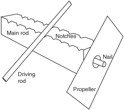
Gee-haw whammy diddle is a scientific toy of a slightly different type. It consist of a wooden base-stick equipped with a series of notches on one of its sides with a propeller loosely attached to its end so that it can freely rotate (Fig. 1).
Another stick is used to rub the first one on the notches, which causes the propeller to rotate. Skilled performers are able to achieve very high rotation speed of the propeller and change the rotation direction very quickly.
Being it a mechanical device, one would expect to be able to pinpoint a simple and clear explanation, why and how a linear motion along the notches causes a circular motion of the propeller and what defines the direction of this motion. This is however not the case in spite of the fact that research on this topic lasts for almost a century. In one of the first works on this topic Leonard Leonard suggests that the propeller vibrates due to elliptical motion of the end of the stick and that the direction of the motion is determined by the phase shift between the vertical and horizontal stick vibrations, caused by different rubbing directions.
This idea was further developed in Schichting where the direction of the rotation is suggested to be connected to the way the stick is being held by hand. Authors also provide basic numerical outputs given the possibilities of computers of that period. Almost a decade later three other papers appeared on this topic. M. J. Clifford et. al. Clifford suggested to link the problem to chaotic orbits of parametrically excited pendulum. Jun Satonobu et. al. Satonobu provided probably the most complex analysis of the problem from both theoretical and experimental point of view so far and concluded the validity of the original hypothesis that the rotation direction is determined by the elliptical movement of the end of the stick and its areal velocity. However the presented experiment concluded only one-side implication of the hypothesis, namely that an elliptical movement of the stick causes the rotation of the propeller into given direction, but did not show that this is the only/prevailing cause of the movement in the real toy.
Further analytical and experimental research was performed by Wilson in Wilson . Results presented here partially contradict the previous work in claiming that the direction of the rotation of the end of the stick does not necessarily defines the direction of the propellers motion. He also presented the hypothesis that the frequency of rotation of the propeller is synchronized with the driving frequency of the notches. However this work has a few limiting factors incorporated. In the analytical part no slip is assumed between the stick and the propeller, which makes the problem and its solution similar the hula-hoop problem, however there is no experimental evidence for this assumption. In the experiment, recordings were performed with very low time resolution (30 fps) which apparently led to rather imprecise results of the motion of the stick. Recently in Bhattacharjee the problem was re-considered by connecting it to Kapitza pendulum and recalling the idea of synchronization between the motion of the stick and the propeller.
In this paper we perform full experimental analysis of the gee-haw whammy diddle toy. We concentrate on the way how different types of movements of the end of the stick cause the propeller to rotate and analyze not only the movement direction, but also its speed depending on various parameters of the movement (amplitude, frequency, areal velocity etc.). We show that most of the hypothesis presented in the literature so far fail under rigorous experimental tests - areal velocity (elliptical movement) of the stick is not needed to excite the propeller to high speed rotations and this speed is not connected to the frequency of vibrations. We suggest that the rotation is a result of a simple positive-feedback mechanism between the motion of the stick and the propeller and its direction (in the absence of the areal velocity) is given by a random fluctuation. The speed of rotation is determined by a combination of amplitude and frequency of the stick vibration and the highest speeds are achieved when the typical stick acceleration is about the gravitational acceleration.
II Experiment
Gee-haw whammy diddle in its original form is practically an uncontrollable device. The fact that it is hold in one hand and rubbed by the other one does not allow any reasonable control of the excitation parameters, neither the exact position of the stick, nor its movement. In previous works Satonobu ; Wilson different mechanical devices were suggested that partially fixed the issue of holding the stick, but kept the rather complicated way of stick excitation by rubbing. Although this mimics the original idea of the device, it is connected with many complications. First, as the rubbing stick needs to moved there and back in a periodic movement, the frequency of the oscillations (caused by running through the notches) if far from being constant. The amplitude of oscillations also depends on the position of the stick (notches closer to the end of the stick cause smaller amplitude then the ones closer the the fixing) and on its speed (higher speed means stronger collisions). By keeping this system in its original form it is nearly impossible to separate relevant parameters that influence the motion of the propeller.
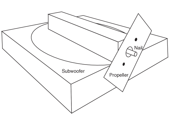
Therefore we decided to redesign the experiment to concentrate solely on the motion of the end of the stick. Instead of rubbing it on its notches, we attached the stick to a subwoofer and vibrated it by different frequencies and amplitudes (Fig. 2).
We also changed the position of the stick on the subwoofer (from center towards the end) to simulate different combinations of horizontal and vertical vibrations. The phenomenon was recorded by a high speed camera that allowed to track both the movement of the end of the stick and the propeller.
This configuration has several advantages. First, both the amplitude and the frequency of the oscillations are well controllable. The frequency is uniquely defined by the frequency of the sound from the signal generator; amplitude of oscillations depends on more parameters - amplitude of the signal, its frequency and exact positioning of the device on the subwoofer, but is perfectly stable once these parameters are fixed. Importantly, the movement of the stick is harmonic in both directions, contrary to the intrinsically inharmonic movement resulting from collisions between the sticks. This all allowed us to perform well controllable experiments in order to distill the leading physical effects that influence the motion of the propeller.
II.1 Experimental conditions
To keep the experimental setup as close to the original problem as possible, let us analyze the Gee-haw whammy diddle frequencies. While rubbing the stick by hand, the hand usually makes a few (say up to three) full cycles (there and back) on the stick per second. There are usually in the order of 10 notches on the stick which results into say up to impulses per second. This is however only a very rough estimate, as the hand does not move with a constant velocity there and back (resulting in a continuous range of frequencies) and the inharmonic impulses themselves produce a broad Fourier spectrum in oscillations. Using a subwoofer with frequency range from Hz to Hz allowed us to simulate the leading frequencies which, as shown below, turn to be enough to reproduce the effect – Hz was chosen for experiments with frequency taken as a fixed parameter. This itself is an important observation, as some of the hypotheses Wilson ; Bhattacharjee suggested a synchronization effect between the oscillations of the stick and the rotation of the propeller, which would require a broad spectrum of frequencies (or their time dependance) for starting the rotation.
The amplitudes of the motion also mimic the original problem. While on the lower end there was no technical limitation, the maximal amplitudes were restricted by the construction of the subwoofer. For central placement of the stick and optimal frequencies of the subwoofer the vertical amplitude reached as much as mm, where for edging frequencies and border placement it was closer to a few mm. This again turned to be sufficient as we were able to reach the optimal conditions for propeller rotation well within the range.
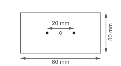
It turned out that while the construction of the rod (a simple stick with a nail on its end) does not crucially influences the movement, this is not the case for the propeller (so much neglected in the previous work). This is mainly due to the fact that if the center of gravity does not coincide with the center of the hole in the propeller, the propeller has a preferred position hanging on the notch and the start of the rotation is more complicated. Even more importantly for small holes, if the center of gravity is outside of the hole, other mechanisms then those described below are needed to start the oscillations. Due to this we decided to use laser-cut propellers in the shape of a rectangle with dimensions of mm mm mm and a hole of different diameters ( mm) cut in the center with great precision, with weight of g depending on the diameter of the hole. Two points were also engraved on the propeller mm apart (see Fig. 3) to allow tracking of the exact position of the propeller.
The whole motion was recorded on a camera with optically stabilized lens system with fps and Full HD () resolution. Position of the nail and the points on the propeller was tracked with a tracking software (Tracker). This allowed us to track more than points per period even for the highest oscillations speeds (and more than for the most extensively used frequency) with a precision in the order of a few m. This is below the resolution of a single pixel (m per pixel) due to the fact that the tracking software analyzed whole area of pixels and was able to determine the center of the area with higher accuracy. This all lead to a well precise description of the movement of the nail.
II.2 Data processing
Two points on the side of the propeller were used to determine two parameters – position of the center of the propeller and its angle (determining the angular velocity, the final output measure). Three complications were connected with processing of the data.
First, two engraved points were designed to be symmetrically displaced from the center of the propeller. Due to the fact that the engraving was performed by a different device than the cut itself, imperfections in the order of mm arose. This was however easily corrected by analyzing a set of frames in the tracker software and adding a suitable offset to the position in the middle of these two points.
The second problem was connected with the finite readout time of the camera. Readout of the whole image took about s, making it roughly ns per row. This means that in the vertical position of the propeller the upper point was read out about s before the nail and the lower point was delayed by about the same time. This naturally biases both the position of the center of the propeller and its angle. This bias can be removed recurrently in the following way.
Tilt of the propeller is calculated for each frame from raw data without any correction. From this data the speed of the propeller can be determined in th order. The time margin (or delay) of the point on the propeller can be calculated by
| (1) |
where and are the raw positions of the dot and nail (in pixels) respectively. Using this time delay and the estimation of the speed of the propeller one can calculate the first correction of the point on the propeller that it is expected to reach in the time when the point of the nail was recorded
| (2) | ||||
| (3) |
where is the distance between to point and the nail, which can be well approximated as the radius of the propeller (taken as half of the distance between the two engraved points). These two points can serve as the input for the next round of the recursive correction by obtaining a more precise tilt and speed of the propeller. However it turned out that the first level is sufficient enough to correct the influence of this effect below other experimental imperfections.
There is another problem connected with the processing of the tilt of the propeller. As it will be explained below, in many cases the motion of the propeller is close to a free movement interrupted with short collision with the nail. In certain cases the collision happens between the readouts of the first and the second point on the propeller. Then the tilt in the specific frame is wrongly calculated and this causes jumps in the calculated speed of the propeller. There are two possible ways to tackle this problem. One, obvious, is to simply ignore those readouts where the speed of the propeller is significantly deviating in two subsequent points. The other one is to detect the times of the collisions from changes in the translational movement of the center of the propeller and ignore readouts for these frames. However, both these processes basically just remove part of the data gathered. In the results presented below we plot frequency of the propeller without any of these corrections, which makes it rather volatile, oscillating around its stable value, but clearly showing the level of readout errors. If some of the data is removed, the frequencies are just smoothed around its local stable values.
III Observations
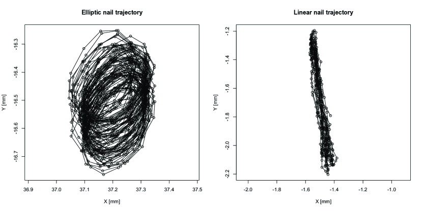
We start the presentation of our results by general observations of the movement of the propeller depending on relevant parameters. In Fig. (4) the readings of the position of the nail are presented for two cases – one is elliptical, resulting from positioning of the stick on side of the subwoofer and one straight and nearly vertical, when the stick was placed in the center. This shows that with our experimental device we were able to mimic the outcomes produced in the close-to-original gee-haw whammy diddle in Refs. Wilson ; Satonobu . For elliptical movement we confirmed the results obtained so far that the direction of the rotation of the propeller was predefined by the direction of the elliptical movement (areal velocity). However, very interestingly, we were able to observe significant speeds of the propeller also in the case where no areal velocity was present in the movement of the nail (right-hand side of the Fig. 4), although in this case the direction of the movement was random when started from a still position and not changed if an initial push was given to the propeller. Therefore we concluded the proposition:
Proposition III.1
Elliptical movement of the nail is not necessary for starting and maintaining the rotation of the propeller and the value of the speed of the propeller is not connected with the areal velocity of the movement of the nail.
In what follows we concentrated our effort on the purely linear movement of the nail, opening a very interesting fundamental question – what is the principle that allows such a simple movement to cause the propeller to rotate? The sole two remaining parameters of the nail movement are its frequency and amplitude. We performed an extensive set of measurements with different combinations of these two parameters and were measuring the speed of the propeller without taking into account its direction. We introduce a joint parameter of the nail movement, namely its maximal acceleration
where is the amplitude of the nail’s movement and its frequency. All results obtained are combined in Fig. (5). Based on these results we formulate the following proposition:
Proposition III.2
The propeller only rotates if the nail during its movement de-touches from the propeller, thus moves down with acceleration exceeding gravity. Further increase of the acceleration leads to smaller propeller speeds.
This proposition can be explained by a model where the movement of the propeller is caused by collisions between the nail and the propeller rather then by continuous movement of the nail along with the propeller (similar to the way how hula-hoop is being explained). In this model, the nail needs to de-touch from the propeller while moving down to allow an impact when returning back. This model qualitatively also explains why the optimal speed is reached for accelerations between and . First it is important to notice that the mean absolute value of the acceleration is , so if the maximal acceleration is , the ”typical one” is . If the typical acceleration is around , the time the propeller stays de-touched from the nail during its way down is maximized. For higher values of acceleration the nail quickly reaches the bottom edge of the hole in the propeller and the driving cannot proceed. For higher acceleration also the forces during the ”touching phase” are larger and cause higher deceleration of the propeller speed due to friction.
To examine this model in a more detail we focused on the movement of the propeller. As its tilt and rotational speed are biased by fluctuations explained above, we first concentrate on the translational movement. In Fig. (6) we present the motion of the center of the propeller on time. It can be seen that the motion during most of the time is governed by the free fall equation (constant speed in x-direction and constant acceleration in y-direction), interrupted by occasional collisions and short periods of continuous touching.
Therefore we formulate the proposition:
Proposition III.3
For largest speeds of the propeller, its motion can be described by free fall motion and short collisions with the nail.
IV Model
Based on the propositions formulated in the previous section we built up a theoretical model. The model is based on the assumption that the movement of the propeller is driven mainly by short collisions between the propeller and the nail and most of the time moves freely. This assumption is backed up by the observation of the translational movement depicted in Fig. (6), but also on the direct observation of video recordings from which it is clear that most of the time the propeller does not touch the nail.
Naturally, the crucial point in this model is to describe the collisions, as (up to air friction) the movement in between the collisions is trivial. Experimental data allows as to describe with a high precision the position of the center of the nail and, knowing its diameter, also its boundary. We can also describe the center of the propeller and boundary of the hole, but due to imperfections based on the readout delay, exactly in those frames in which a collision occurred this description is inaccurate. So basically for most of the frames we get perfect data, that allows us to pinpoint both the nail and the propeller, but for the interesting frames including collisions this is not the case.
Due to this we had to build up a model that does not relay on detecting and describing the collisions based on comparing the positions of the nail and the propeller, but rather on abrupt change of translational velocity of the propeller. For a very short collision that happens at an angle between a vertically moving nail and the propeller we model the impact by two integrated forces:
| (4) |
acting on the propeller outwards from its center
| (5) |
in perpendicular direction, where is the friction coefficient between the nail and the propeller, which can be negative – the sign determines in which direction the friction force is acting. In principle the friction force can be smaller as well if there is no slipping on the touching point, which is however not possible for fast moving propellers, so we do not take this possibility into account.
These two impacts will change both the momentum in and direction of the propeller, as well as the angular momentum of the propeller in the following way:
| (6) | ||||
| (7) | ||||
| (8) |
where is the radius of the hole in the propeller. There is no experimental way how to directly measure for an individual collision, but we can treat it as a variable and solve for it from the first two equations, and plug it into the last one. We get
| (9) |
which can be directly calculated for each frame by knowing the , and . Change of momentum in x direction in the collision is simply given by its change between the frames, as there are no other forces acting in this direction. This is not the case for , where one need to subtract the contribution of the gravitational acceleration given by
| (10) |
where is the mass of the propeller and is the time of one frame. The angle can be also determined from the position of the nail and the propeller. It is interesting to see that the resulting change in angular momentum (9) is independent on the friction coefficient
Let us recall here that the sum of the momenta in direction (6), as well as in direction (7) corrected for the gravitational force (10) shall be close to zero for any subsequent set of frames, which can serve as a sanity check on the data. On the other hand if the propeller accelerates its rotation or even keeps it constant, the sum of angular momentum contribution should be positive or negative (depending on the direction of the rotation) and increasing its value for an increasing number of subsequent frames.
V Results
We have analyzed the angular momentum contributions (9) for different types of motion of the propeller – running rotation in both directions and rotation accelerating from still point. In Fig. (7) we can see that the aggregated angular momentum is clearly increasing with time. Part of this momentum is lost in friction and part is utilized for increasing the frequency of the propeller. The same kind of data is plotted in Fig. (8) for the negative direction of propeller movement. Despite the direction, all other results are very similar: both the final frequency and the aggregated angular momentum per second.
We also analyzed the starting period of the movement in Fig. (9).
Here less of the aggregated momentum is lost in friction (so the propeller accelerates), but on the other hand the efficiency of the aggregation is much smaller, especially in the starting phase.
In principle, one can divide the frames of the recording into two types, with and without collisions. In the first one and (10), leading to , whereas in the others these values should be nonzero (and, for relevant collisions, not to small). However, taking the experimental errors into account, in all frames both and are non-zero. One would expect that the influence of these frames is negligible for the total aggregated angular momentum. To test this hypothesis we can set a threshold for the total change in the momentum
| (11) |
per frame and count only aggregated momentum from frames for which this treshold is reached. The other equivalent option is to take a specific number of frames with the highest change of translational momentum (11) and look at the total aggregated angular momentum.
In Fig. (10) we show the dependance of the total aggregated angular momentum depending on the number of frames taken. Is can be clearly seen that the main aggregation happens in about of the frames with highest change of translational momentum, corresponding to the collisions. This corresponds also to the observation of the video recordings that a collision happens a few times during one period of the nail movement. Contribution of the rest of the frames composes from the contribution of weaker collisions and noise and in total is insignificant. This confirms the proposition that the propeller gains most of the angular momentum causing rotation within short collisions rather than by continuous touching of the nail.
VI Conclusion
Gee-haw whammy diddle is a very interesting mechanical scientific toy that demonstrates the changes of linear driving to rotational movement. Within this paper we have performed an extensive experimental research of the devise, aiming to pinpoint the essential phenomenon that causes the propeller to rotate. Contrary to hypotheses presented in previous works on this topic, in particular in Wilson ; Satonobu , we have shown that the elliptical movement of the stick is not necessary to induce the rotational movement of the propeller – on the contrary, purely linear motion of the stick induces the highest speeds of the propeller. We have also shown that in contrary to ideas presented in Wilson ; Bhattacharjee there is no synchronization effect between the motion of the tick and the propeller – by purely harmonic motion of the stick the propeller was able to accelerate from rest to high frequencies (however not reaching the driving frequency) and the stabilized speed of the propeller was strongly dependent on the amplitude of the oscillations.
We showed that the highest speed of the propeller can be reached for parameters of the oscillations that secure the typical acceleration of the stick to be roughly equal to gravitational acceleration. This is due to the fact that, as concluded from the motion of the propeller and direct observation, best results are achieved for situations where most of the time the propeller is not touching the nail at the end of the stick. In this case the propeller is being translationally stabilized by short collisions with the moving nail that, in total, supply a flow of angular momentum. The direction of rotation is, for linear stick movement, random. Gee-haw whammy diddle is often compared to hula-hoop, also a well-known effect used for physics demonstration. We believe that this comparison is rather imprecise due to the fact that the governing physical effects are pretty much different in those two cases. One could probably compare gee-haw whammy diddle better to the Devil stick juggling, where one stick is being held in hand and used to rotate another stick freely flying in the air.
Acknowledgments
Work was motivated by the IYPT 2017 problem number 14 (www.iypt.org). This research was supported by the VEGA 2/0043/15 project. MP would like to thank PosAm for generous support.
References
- (1) R. W. Leonard, Am. J. Phys. 5, 175 (1937)
- (2) H. J. Schichting, and U. Backhaus, Physik und Didaktik 16/3, 238 (1988)
- (3) M. J. Clifford, S. R. Bishop, Physics Letters A, 191 – 196 (1995)
- (4) J. Satonobu, S. Ueah, and K. Nakamura, Jpn. J. Appl. Phys. 34, 2745 - 2751 (1995)
- (5) J. F. Wilson, Int. J. Non-Linear Mechanics, 33, 2, 189-200 (1998)
- (6) S. Bhattacharjee, arXiv:1307.6698 (2013)