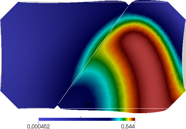
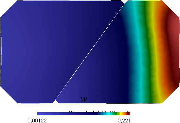
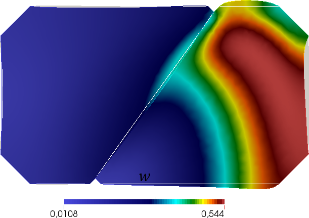
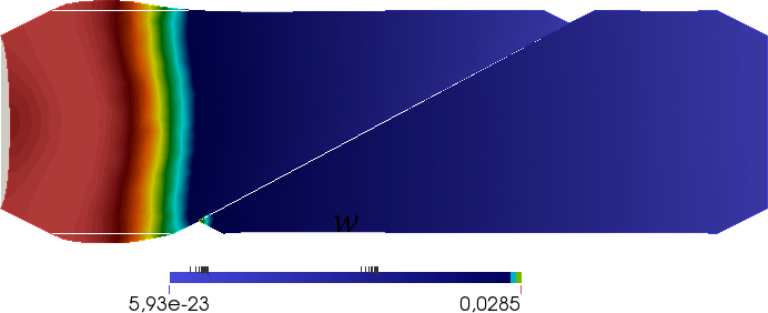
A modeling framework for contact, adhesion and mechano-transduction between excitable deformable cells

Pietro Lenarda Alessio Gizzi Marco Paggi
Abstract

Cardiac myocytes are the fundamental cells composing the heart muscle. The propagation of electric signals and chemical quantities through them is responsible for their nonlinear contraction and dilatation. In this study, a theoretical model and a finite element formulation are proposed for the simulation of adhesive contact interactions between myocytes across the so-called gap junctions. A multi-field interface constitutive law is proposed for their description, integrating the adhesive and contact mechanical response with their electrophysiological behavior. From the computational point of view, the initial and boundary value problem is formulated as a structure-structure interaction problem, which leads to a straightforward implementation amenable for parallel computations. Numerical tests are conducted on different couples of myocytes, characterized by different shapes related to their stages of growth, capturing the experimental response. The proposed framework is expected to have impact on the understanding how imperfect mechano-transduction could lead to emergent pathological responses.

1 Introduction

Computational modeling of soft biological tissues represents a major field of research since the last two decades, see e.g. [1, 2, 3] for fundamental textbooks and review articles. The accurate mathematical description of excitable deformable cells and tissues has received increasing attention due to the complexity of the involved interactions [4, 5, 6] in which mechano-regulated cellular processes are key features [7, 8] demanding also the development of novel experimental techniques for their characterization and understanding [9]. A vast literature on this topic relies on cardiovascular modeling and development [10] highlighting as soft biological tissues, and cardiac cells in particular, span a wide range of spatial and temporal scales [11, 12, 13].

A cardiomyocyte is the functional unit of the heart at the micro-scale in which dedicated intracellular and intercellular mechanisms allow cardiac cells to work as a syncitium [14]. Synchrony is the result of a fast propagation of the electrical impulse from a cell to another over the subsequent cardiac compartments. Current flow-mediated propagation of the electrical impulse is ruled by clusters of inter-cellular proteic channels (mainly Cx43) [15, 16], namely gap junctions (GJ) [17, 18] that are voltage- and time-dependent and can induce important effects on the overall emerging dynamics [19]. Mechanotransduction, in addition, allows cardiomyocytes to convert a mechanical signal to a change in cell growth or remodeling [20, 21]. Abnormal mechanotransduction, however, can lead to a variety of diseases [22, 23] and understanding the connection between diseases and imperfect cell-cell interactions or mechanical damage is a cutting-edge research topic [24].

A progress with respect to the state-of-the-art requires a novel theoretical framework integrating modeling of biological cell interactions within a multi-field approach [25]. While this integration of methods is still unchallenged due to the high computational and modeling complexities, relevant contributions regard finite element procedures for the theoretical description of single cell contractility responses under different environmental stimuli [26, 27, 28, 29, 30] or whole reconstructed heart geometries for selected pathological states [31]. In order to incorporate dominant mechanisms occurring at different scales within a constitutive framework for the cardiac tissue, microstructural properties have to be properly described, including mechano-regulated interactions occurring among tissue constituents. Though our modeling refers to the cell micro-scale, we assume a continuum approach [30]. Experimental evidences on single cell contractility showed that forces are induced where no visible stress fibers are present, thus implying that a much finer scale is responsible for the observed phenomena and therefore continuum level considerations can be adopted [27, 32, 33, 34].

Structural and physical properties of contact myocytes, in particular, will be the main object of this study. Intercellular communication between excitable contractile cells concentrates at the intercaleted discs and concerns with microscopic electrical conductance, metabolic and mechanical coupling [35]. A schematic representation of two-dimensional cardiomyocytes contact problems is provided in Fig. 1(a). The interface constitutive model concerns (i) voltage-dependent GJs ruling the electrical conductance for membrane voltage propagation, and (ii) adhesive and contact membrane interfaces dictating mechanical stress localization across adjacent cells. In addition, localized focal adhesions are described via appropriate boundary conditions.

The problem at hand deserves an accurate cellular mechanical description in which structural heterogeneities, appropriate constitutive relations, and active dynamics are the three key factors to be formalized within a generalized theoretical framework [13]. We devise our myocyte contact mechanical model by linking the active electrophysiological processes occurring in the cell with the passive characters at the cell boundaries. The novel constitutive interface formulation we present here does not depend on the details of the electrophysiological and mechanical model, which we keep as simple as possible, rather we develop a general modeling framework that can be appropriately modified and enriched according to the selected case study.

The present work introduces two important novelties with respect to the current literature. First, we extend the single cell study proposed in [30] by formulating a novel interface constitutive model among cardiac myocytes in electromechanical contact problems, reproducing several experimental evidences [36]. Second, we provide a consistent derivation of a computationally stable staggered finite element procedure for solving the two-dimensional nonlinear coupled structure-structure electromechanical contact problem for the interaction of two excitable deformable domains.

The paper in organized as follows. In Section 2, the complete continuum formulation of the active-strain model is provided. Section 3 describes its weak and discretized forms. In Section 4, a self-consistent theoretical framework for the interface model is provided together with weak and discretized forms. Section 5, concerns with the complete description of the implicit scheme for finite element implementations. In Section 6, numerical applications are reported and validated against experimental evidences. Conclusions, limitations and future perspectives are provided in Section 7. The manuscript is equipped with extended appendices providing all the necessary derivations of the operators required for the implementation of the methodology within finite element procedures.

2 Continuum model of the active-strain myocyte

In this section, the mechanical and electrophysiological model used in numerical simulations for a single myocyte is briefly outlined. The mechanical model is based on the active-strain formulation [37, 38]. The activation variables dynamics, which are responsible for the contraction and thickening along the fibers vectors, are ruled by the two-variable phenomenological Rogers-McCulloch’s model [39].
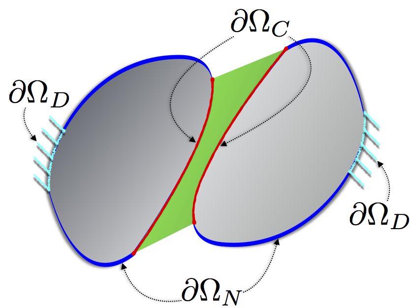
Refer to caption
Refer to caption
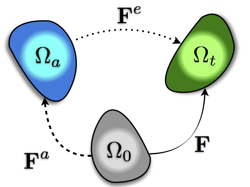
Figure 1: Schematic representation of (a) imposed boundary conditions, e. g., Dirichlet, ΩDsubscriptΩ𝐷\partial\Omega_{D}, Neumann, ΩNsubscriptΩ𝑁\partial\Omega_{N}, and Contact, ΩCsubscriptΩ𝐶\partial\Omega_{C}; (b) multiplicative decomposition of the deformation gradient in total 𝐅𝐅{\mathbf{F}}, active, 𝐅asubscript𝐅a{{\mathbf{F}}_{\rm a}}, and elastic, 𝐅esubscript𝐅e{\mathbf{F}_{\rm e}}, maps associated with the reference, Ω0subscriptΩ0\Omega_{0}, active, ΩasubscriptΩ𝑎\Omega_{a}, and current, ΩtsubscriptΩ𝑡\Omega_{t}, configurations.

2.1 Finite kinematics

The kinematics of active deformable cells is framed within the classical description of continuum mechanics under finite elasticity assumptions and specialized for two-dimensional domains. In the following, 𝑿𝑿{\boldsymbol{X}} denotes the material position vector in the reference (undeformed) configuration Ω02subscriptΩ0superscript2\Omega_{0}\subset\mathbb{R}^{2}, and 𝒙=𝑿+𝒖𝒙𝑿𝒖{\boldsymbol{x}}={\boldsymbol{X}}+{\boldsymbol{u}} stands for the spatial position vector in the current (deformed) configuration Ωt2subscriptΩ𝑡superscript2\Omega_{t}\subset\mathbb{R}^{2} at a generic time t𝑡t, being 𝒖𝒖{\boldsymbol{u}} the displacement vector. The boundary ΩΩ\partial\Omega of the myocyte are assumed to be Lipschitz continuous with Ω=ΩDΩNΩsubscriptΩ𝐷subscriptΩ𝑁\partial\Omega=\partial\Omega_{D}\cup\partial\Omega_{N} where ΩDsubscriptΩ𝐷\partial\Omega_{D} and ΩNsubscriptΩ𝑁\partial\Omega_{N} denote the portions of the boundary subject to Dirichlet and Neumann boundary conditions, respectively. The deformation gradient tensor is 𝐅=𝑿𝒙𝐅subscript𝑿𝒙{\mathbf{F}}=\nabla_{{\boldsymbol{X}}}{\boldsymbol{x}}, and the Jacobian of the transformation is J=det𝐅𝐽𝐅J=\det{\mathbf{F}}.

In order to encompass the nonlinear coupling between the electrophysiological dynamics and the hyperelastic material response induced by the excitation-contraction mechanisms in cardiomyocytes, the well established multiplicative decomposition of the deformation gradient into an elastic and inelastic part is assumed:

𝐅=𝐅e𝐅a.𝐅subscript𝐅esubscript𝐅a{\mathbf{F}}={\mathbf{F}_{\rm e}}{{\mathbf{F}}_{\rm a}}. (1)

Here, the active deformation gradient, 𝐅asubscript𝐅a{{\mathbf{F}}_{\rm a}}, is provided by the subcellular calcium/voltage dynamics. The sketch of the multiplicative decomposition shown in Fig. 1(b) accounts for the intermediate non compatible fictitious configuration ΩasubscriptΩ𝑎\Omega_{a} in which all the inelastic processes take place [37, 40].

Let 𝐚lsubscript𝐚𝑙\mathbf{a}_{l}, 𝐚tsubscript𝐚𝑡\mathbf{a}_{t} be the vectors of fiber sheet in longitudinal and transversal directions, respectively. Based on the active-strain approach [41], the planar active anisotropic deformation gradient tensor is built as:

𝐅a=𝐈+γl𝐚l𝐚l+γt𝐚t𝐚t,subscript𝐅a𝐈tensor-productsubscript𝛾𝑙subscript𝐚𝑙subscript𝐚𝑙tensor-productsubscript𝛾𝑡subscript𝐚𝑡subscript𝐚𝑡{{\mathbf{F}}_{\rm a}}=\mathbf{I}+\gamma_{l}\mathbf{a}_{l}\otimes\mathbf{a}_{l}+\gamma_{t}\mathbf{a}_{t}\otimes\mathbf{a}_{t}, (2)

where γl,γtsubscript𝛾𝑙subscript𝛾𝑡\gamma_{l},\gamma_{t} are smooth scalar activation functions representing, respectively, the active shortening of the cardiomyocytes in the longitudinal direction and the corresponding thickening in the transversal direction. The activation functions are such that:

γt=γl1+γl,subscript𝛾𝑡subscript𝛾𝑙1subscript𝛾𝑙\gamma_{t}=-\dfrac{\gamma_{l}}{1+\gamma_{l}}, (3)

to achieve the incompressibility of the cell [42], i.e., Ja=det𝐅a=(1+γl)(1+γt)=1subscript𝐽asubscript𝐅a1subscript𝛾𝑙1subscript𝛾𝑡1{J}_{\rm a}=\det{{\mathbf{F}}_{\rm a}}=(1+\gamma_{l})(1+\gamma_{t})=1.

2.2 Electrophysiological model

Several electrophysiological models for the cardiac cells are available in the literature, adopting phenomenological or physiological approaches based on reaction-diffusion formulations [43]. In the present study, the Rogers-McCulloch’s model [39] is adopted for the description of the coupled model ruling the voltage potential and the Calcium concentration. The model has been demonstrated to capture the main features of the action potential spatio-temporal dynamics with a reduced mathematical complexity. Other possible extensions available in the literature (see e.g. [44]) could be used for the continuum, without any loss of generality.

The nondimensional phenomenological model is formulated as a set of nonlinear partial differential equations describing the reaction-diffusion (RD) system ruling the coupled dynamics of dimensionless membrane voltage V𝑉V and the Calcium-like concentration w𝑤w, defined in Ω0×[0,T]subscriptΩ00𝑇\Omega_{0}\times[0,T], namely:

tV+1J(𝐅1𝐃𝐅TV)I(V,w)subscript𝑡𝑉1𝐽superscript𝐅1superscript𝐃𝐅T𝑉𝐼𝑉𝑤\displaystyle\partial_{t}V+\dfrac{1}{J}\nabla\cdot\left(\mathbf{F}^{-1}{\mathbf{D}}\mathbf{F}^{-\rm T}\nabla V\right)-I(V,w) =Iapp,absentsubscript𝐼app\displaystyle=I_{\rm app}, (4a)
dtwH(V,w)subscript𝑑𝑡𝑤𝐻𝑉𝑤\displaystyle d_{t}w-H(V,w) =0,absent0\displaystyle=0, (4b)

where 𝐅1𝐃𝐅Tsuperscript𝐅1superscript𝐃𝐅T{\mathbf{F}}^{-1}{\mathbf{D}}{\mathbf{F}}^{-\rm{T}} is the anisotropic second order tensor of tissue conductivities obtained as the pull-back of 𝐃=diag(Dl,Dt)𝐃diagsubscript𝐷𝑙subscript𝐷𝑡{\mathbf{D}}=\operatorname*{diag}(D_{l},D_{t}) in the planar deformed configuration [30, 37]; tsubscript𝑡\partial_{t} and dtsubscript𝑑𝑡d_{t} denote partial and total derivatives in time, respectively; \nabla\cdot and ()\nabla(\cdot) are the divergence and gradient operators, respectively; Iappsubscript𝐼appI_{\rm app} represents the external electric current. The other electrophysiological functions are given by

I(V,w)𝐼𝑉𝑤\displaystyle I(V,w) =c1V(Va)(1V)c2Vw,absentsubscript𝑐1𝑉𝑉𝑎1𝑉subscript𝑐2𝑉𝑤\displaystyle=c_{1}V(V-a)(1-V)-c_{2}Vw, (5a)
H(V,w)𝐻𝑉𝑤\displaystyle H(V,w) =b(Vdw),absent𝑏𝑉𝑑𝑤\displaystyle=b(V-dw), (5b)

specializing the well-known FitzHugh-Nagumo model to cardiac dynamics [43]. Model parameters are a=0.13𝑎0.13a=0.13, c1=0.26subscript𝑐10.26c_{1}=0.26 ms-1, c2=0.1subscript𝑐20.1c_{2}=0.1 ms-1, b=0.013𝑏0.013b=0.013 ms-1, d=0.1𝑑0.1d=0.1.

2.3 Active mechanics

The constitutive prescription for the free energy density reads:

Ψ=μ2Jatr(𝐅eT𝐅e𝐈)p(J1),Ψ𝜇2subscript𝐽𝑎trsuperscriptsubscript𝐅eTsubscript𝐅e𝐈𝑝𝐽1\displaystyle\Psi=\dfrac{\mu}{2}J_{a}\text{tr}\left({\mathbf{F}_{\rm e}}^{\rm T}{\mathbf{F}_{\rm e}}-\mathbf{I}\right)-p(J-1), (6)

where p𝑝p is the Lagrange multiplier arising from the imposition of the incompressibility constraint J=1𝐽1J=1 (conservation of mass) and which is usually interpreted as the hydrostatic pressure field, while μ𝜇\mu is the shear modulus. According to Eq. (6), the first Piola-Kirchhoff stress tensor reads:

𝐏𝐏\displaystyle{\mathbf{P}} =\displaystyle= μJa𝐅𝐅a1𝐅aTJp𝐅T.𝜇subscript𝐽𝑎superscriptsubscript𝐅𝐅a1superscriptsubscript𝐅aT𝐽𝑝superscript𝐅T\displaystyle\mu J_{a}\mathbf{F}{{\mathbf{F}}_{\rm a}}^{-1}{{\mathbf{F}}_{\rm a}}^{-\rm T}-Jp\mathbf{F}^{-\rm T}. (7)

As a limit case, if coupling with the electrical variables is neglected, then the mechanical model reduces to a standard incompressible neo-Hookean material with strain energy density function Ψ=μ2(tr(𝐅T𝐅)3)p(J1)Ψ𝜇2trsuperscript𝐅T𝐅3𝑝𝐽1\Psi=\dfrac{\mu}{2}(\text{tr}(\mathbf{F}^{\rm T}\mathbf{F})-3)-p(J-1). Again, this modeling assumption does not reduce the generality of the approach and other generalized hyperelastic models can be easily introduced.

Let consider a unit square domain made of a neo-Hookean material, constrained on the left hand side boundary, and apply on the right hand side a constant displacement u1subscript𝑢1u_{1}. Let εxsubscript𝜀𝑥\varepsilon_{x} be the resulting strain in the x𝑥x-direction and let λ=λ1=εx+1𝜆subscript𝜆1subscript𝜀𝑥1\lambda=\lambda_{1}=\varepsilon_{x}+1 be the stretch. The resulting Cauchy stress σxsubscript𝜎𝑥\sigma_{x} is given by:

σx=μ(λ21λ).subscript𝜎𝑥𝜇superscript𝜆21𝜆\sigma_{x}=\mu\left(\lambda^{2}-\dfrac{1}{\lambda}\right).

The dimensionless Cauchy stress σx/μsubscript𝜎𝑥𝜇\sigma_{x}/\mu predicted by a neo-Hookean material for various values of the shear modulus μ𝜇\mu, is shown in Fig. 2 vs. the uniaxial stretch λ𝜆\lambda.

Refer to caption
Figure 2: Dimensionless Cauchy stress component σx/μsubscript𝜎𝑥𝜇\sigma_{x}/\mu vs. stretch λ𝜆\lambda for different values of the shear modulus μ𝜇\mu.

2.4 Activation dynamics

The mathematical formulation of the activation mechanisms in the myofilaments adopted here is based on the arguments in [37]. The activation dynamics is assumed to depend on the recovery variable w𝑤w as:

fCa(w)subscript𝑓𝐶𝑎𝑤\displaystyle f_{Ca}(w) =12+1πatan[βclog(wc0+ϵ)],absent121𝜋atandelimited-[]subscript𝛽𝑐𝑤subscript𝑐0italic-ϵ\displaystyle=\dfrac{1}{2}+\dfrac{1}{\pi}\text{atan}\left[\beta_{c}\log\left(\dfrac{w}{c_{0}}+\epsilon\right)\right], (8a)
λCasubscript𝜆𝐶𝑎\displaystyle\lambda_{Ca} =fCa(c)1fCa(c)γ0max,absentsubscript𝑓𝐶𝑎superscript𝑐1subscript𝑓𝐶𝑎superscript𝑐subscriptsuperscript𝛾0\displaystyle=\dfrac{f_{Ca}(c^{*})-1}{f_{Ca}(c^{*})-\gamma^{\max}_{0}}, (8b)
γ0subscript𝛾0\displaystyle\gamma_{0} =γ0maxλCa1+fCa(w),absentsubscriptsuperscript𝛾0subscript𝜆𝐶𝑎1subscript𝑓𝐶𝑎𝑤\displaystyle=\gamma^{\max}_{0}\dfrac{\lambda_{Ca}}{1+f_{Ca}(w)}, (8c)

such that γl=γ01subscript𝛾𝑙subscript𝛾01\gamma_{l}=\gamma_{0}-1, and γtsubscript𝛾𝑡\gamma_{t} is given by Eq. (3). The constant ϵitalic-ϵ\epsilon is a stabilization term needed for numerical reasons and parameters are: βc=6subscript𝛽𝑐6\beta_{c}=6, c0=3.2×101mol/lsubscript𝑐03.2superscript101mollc_{0}=3.2\times 10^{-1}\;\rm mol/l, c=101mol/lsuperscript𝑐superscript101mollc^{*}=10^{-1}\;\rm mol/l, γ0max=0.8subscriptsuperscript𝛾00.8\gamma^{\max}_{0}=0.8, and ε=105𝜀superscript105\varepsilon=10^{-5}.

The delay and amplitude of the Calcium-activation interactions can be tuned based on Eq. (8). The described model corresponds to a phenomenological representation of actin–myosin binding kinetics with typical timing and Calcium function shapes (calcium waves leading to local excitations) in agreement with more accurate models coupling voltage and Calcium kinetics [30]. The reaction kinetics of Calcium concentrations and active shortening of the sarcomeres in a single material point behave as depicted in Fig. 3, where a delayed activation (dashed blue line) is present according to the cytosolic Calcium concentration [45]. On the other hand, the present model is not capable of correctly describe force-velocity relationships, as the microscopical information about sarcomere dynamics is not accounted for.

Refer to caption
Figure 3: Time course of electrophysiological variables V𝑉V, w𝑤w and γlsubscript𝛾𝑙\gamma_{l} in a given sarcomere point.

3 Computational model of active myocytes

3.1 Strong and weak forms

The strong form of the problem for a single myocyte Ω0subscriptΩ0\Omega_{0} is given by the following set of nonlinearly coupled partial differential equations for the displacement field 𝒖𝒖{\boldsymbol{u}} and pressure p𝑝p defined in Ω0subscriptΩ0\Omega_{0}, and for the electrical variable V𝑉V and the physiological variable w𝑤w in Ω0×[0,T]subscriptΩ00𝑇\Omega_{0}\times[0,T]:

𝐏𝐏\displaystyle-\nabla\cdot{\mathbf{P}} =0,absent0\displaystyle=0, (9a)
J𝐽\displaystyle J =1,absent1\displaystyle=1, (9b)
tV+1J(𝐅1𝐃𝐅TV)I(V,w)subscript𝑡𝑉1𝐽superscript𝐅1superscript𝐃𝐅T𝑉𝐼𝑉𝑤\displaystyle\partial_{t}V+\dfrac{1}{J}\nabla\cdot\left(\mathbf{F}^{-1}\mathbf{D}\mathbf{F}^{-\rm T}\nabla V\right)-I(V,w) =Iapp,absentsubscript𝐼app\displaystyle=I_{\rm app}, (9c)
dtwH(V,w)subscript𝑑𝑡𝑤𝐻𝑉𝑤\displaystyle d_{t}w-H(V,w) =0.absent0\displaystyle=0. (9d)

The mechanical problem described by Eqs. (9a)(9b) and the electrophysiological problem defined by Eqs. (9c)(9d) are physically coupled via the presence of the term 𝐅a=𝐅a(w)subscript𝐅𝑎subscript𝐅𝑎𝑤{\mathbf{F}}_{a}={\mathbf{F}}_{a}(w) in the equation for 𝐏𝐏{\mathbf{P}} accounting for the activation variables defined by Eq. (8), and geometrically coupled via the presence of the deformation gradient 𝐅𝐅{\mathbf{F}} entering the diffusion tensor in Eq. (9c). The differential problem (9) is equipped with suitable boundary conditions describing the interaction of the myocyte with the extracellular matrix [30]. In the case of a rigid substrate, which is the case when the cell is physically isolated from the rest of the surrounding tissue [36], Neumann and Dirichlet boundary conditions are imposed as vanishing normal tractions on ΩNsubscriptΩ𝑁\partial\Omega_{N} and vanishing displacements on ΩDsubscriptΩ𝐷\partial\Omega_{D}, respectively:

𝐏𝐧=𝟎onΩN,𝒖=𝟎onΩD.formulae-sequence𝐏𝐧0onsubscriptΩ𝑁𝒖0onsubscriptΩ𝐷{\mathbf{P}}\,\mathbf{n}=\mathbf{0}\,\,\,\text{on}\,\,\,\partial\Omega_{N}\,,\qquad\;{\boldsymbol{u}}=\mathbf{0}\,\,\,\text{on}\,\,\,\partial\Omega_{D}\,. (10)

Other boundary conditions can be considered by introducing a bed of deformable springs to simulate other stiffnesses of the extracellular matrix and support typical of experimental lob-on-chip tests [36]. The system of equations has to be finally completed with suitable initial values and no-flux boundary conditions for the voltage V𝑉V and the electrophysiological variable w𝑤w [46, 47].

Hence, in the two-dimensional setting, the formulation contains five field variables, i.e., the displacement field components u1subscript𝑢1u_{1}, u2subscript𝑢2u_{2}, the hydrostatic pressure p𝑝p, the diffusive membrane voltage field V𝑉V and the local Calcium-like dynamics w𝑤w.

Let now introduce the spaces where the weak solution of the problem is defined:
𝒖𝑽:=L2(0,T;[H1(Ω0)]2)𝒖𝑽assignsuperscript𝐿20𝑇superscriptdelimited-[]superscript𝐻1subscriptΩ02{\boldsymbol{u}}\in{\boldsymbol{V}}:=L^{2}(0,T;[H^{1}(\Omega_{0})]^{2}),  pQ:=L2(Ω0)𝑝𝑄assignsuperscript𝐿2subscriptΩ0p\in Q:=L^{2}(\Omega_{0}),   V𝒱:=L2(0,T;H1(Ω0))𝑉𝒱assignsuperscript𝐿20𝑇superscript𝐻1subscriptΩ0V\in{\mathcal{V}}:=L^{2}(0,T;H^{1}(\Omega_{0})), and wW:=L2(0,T;L2(Ω0))𝑤𝑊assignsuperscript𝐿20𝑇superscript𝐿2subscriptΩ0w\in W:=L^{2}(0,T;L^{2}(\Omega_{0})).
The present formulation leads to a mixed displacement-pressure variational problem. We also introduce the test functions for the mechanical problem 𝒗=(v1,v2)T𝑽0𝒗superscriptsubscript𝑣1subscript𝑣2Tsubscript𝑽0{\boldsymbol{v}}=(v_{1},v_{2})^{\rm T}\in{\boldsymbol{V}}_{0}, qQ0𝑞subscript𝑄0q\in Q_{0} and for the electrophysiological problem ξ𝒱0𝜉subscript𝒱0\xi\in{\mathcal{V}}_{0} and ϕW0italic-ϕsubscript𝑊0\phi\in W_{0}, defined on the spaces of the corresponding fields, and vanishing on the Dirichlet part of the boundary. As usual, these functions multiply the strong form equations and the result is integrated over the myocyte domain Ω0subscriptΩ0\Omega_{0}. For the sake of simplicity, we report here the weak form for homogeneous Dirichlet boundary conditions. Applying the divergence theorem, the resulting weak problem is: Find 𝒖𝑽𝒖𝑽{\boldsymbol{u}}\in{\boldsymbol{V}}, pQ𝑝𝑄p\in Q and v𝒱𝑣𝒱v\in{\mathcal{V}}, wW𝑤𝑊w\in W such that the following system is satisfied:

Ω0μJa𝐅𝐅a1𝐅aT:𝒗d𝑿Ω0Jp𝐅T:𝒗d𝑿=0,𝒗𝑽0,:subscriptsubscriptΩ0𝜇subscript𝐽𝑎superscriptsubscript𝐅𝐅a1superscriptsubscript𝐅aT𝒗d𝑿subscriptsubscriptΩ0𝐽𝑝superscript𝐅T:formulae-sequence𝒗d𝑿0for-all𝒗subscript𝑽0\displaystyle\int_{\Omega_{0}}\mu J_{a}\mathbf{F}{{\mathbf{F}}_{\rm a}}^{-1}{{\mathbf{F}}_{\rm a}}^{-\rm T}:\nabla{\boldsymbol{v}}\;{\rm d}{\boldsymbol{X}}-\int_{\Omega_{0}}Jp\mathbf{F}^{-\rm T}:\nabla{\boldsymbol{v}}\;{\rm d}{\boldsymbol{X}}=0,\quad\forall{\boldsymbol{v}}\in{\boldsymbol{V}}_{0}, (11a)
Ω0(J1)qd𝑿=0,qQ0,formulae-sequencesubscriptsubscriptΩ0𝐽1𝑞differential-d𝑿0for-all𝑞subscript𝑄0\displaystyle\int_{\Omega_{0}}(J-1)q\;{\rm d}{\boldsymbol{X}}=0,\quad\forall q\in Q_{0}, (11b)
Ω0tVξd𝑿+Ω01J𝐅1𝐃𝐅TVξd𝑿Ω0Iξd𝑿Ω0Iappξd𝑿=0,ξ𝒱0,formulae-sequencesubscriptsubscriptΩ0subscript𝑡𝑉𝜉d𝑿subscriptsubscriptΩ01𝐽superscript𝐅1superscript𝐃𝐅T𝑉𝜉d𝑿subscriptsubscriptΩ0𝐼𝜉differential-d𝑿subscriptsubscriptΩ0subscript𝐼app𝜉differential-d𝑿0for-all𝜉subscript𝒱0\displaystyle\int_{\Omega_{0}}\partial_{t}V\xi\;{\rm d}{\boldsymbol{X}}+\int_{\Omega_{0}}\dfrac{1}{J}\mathbf{F}^{-1}\mathbf{D}\mathbf{F}^{-\rm T}\nabla V\cdot\nabla\xi\;{\rm d}{\boldsymbol{X}}-\int_{\Omega_{0}}I\xi\;{\rm d}{\boldsymbol{X}}-\int_{\Omega_{0}}I_{\rm app}\xi\;{\rm d}{\boldsymbol{X}}=0,\quad\forall\xi\in{\mathcal{V}}_{0}, (11c)
Ω0dtwϕd𝑿Ω0Hϕd𝑿=0,ϕW0.formulae-sequencesubscriptsubscriptΩ0subscript𝑑𝑡𝑤italic-ϕdifferential-d𝑿subscriptsubscriptΩ0𝐻italic-ϕdifferential-d𝑿0for-allitalic-ϕsubscript𝑊0\displaystyle\int_{\Omega_{0}}d_{t}w\phi\;{\rm d}{\boldsymbol{X}}-\int_{\Omega_{0}}H\phi\;{\rm d}{\boldsymbol{X}}=0,\quad\forall\phi\in W_{0}. (11d)

The nonlinear coupled system of equations (11), equipped with the activation equations (3) and (8) is solved numerically using a finite element procedure, as detailed in Appendix A. Following previous studies [13], the solution strategy is based on a sequential (staggered) approach. This procedure consists in dividing the problem into a mechanical phase, corresponding to the equations (11a) and (11b), and an electrophysiological phase, corresponding to Eqs. (11c) and (11d). At each time step t𝑡t, the mechanical problem is solved first, and then, with the computed values of displacement and pressure, the electrophysiological problem is solved. Both the mechanical and the electrophysiological problems are nonlinear, so that they have to be embedded into a Newton-Raphson iterative scheme to find a solution (see Appendix A for more details).

3.2 Numerical validation of the electromechanical model for a single myocyte

In order to assess the accuracy of the numerical scheme described in the previous section, a series of numerical tests is performed. For the sake of simplicity, we consider equal diffusivity in the longitudinal and transverse direction, i.e. Dl=Dt=103cm2/mssubscript𝐷𝑙subscript𝐷𝑡superscript103superscriptcm2msD_{l}=D_{t}=10^{-3}\,{\rm cm}^{2}/{\rm ms}, and the shear modulus is set as μ=4𝜇4\mu=4 kPa.

The first test is conducted to study the convergence of the electromechanical solver to the physical solution as function of the mesh size hh. Let consider a 2D electromechanical tissue occupying in its reference configuration the squared domain Ω0=[0,2]×[0,2]subscriptΩ00202\Omega_{0}=[0,2]\times[0,2] cm2. The square is clamped on the bottom side, i.e., ΩD={(X1,X2):0X12,X2=0}subscriptΩ𝐷conditional-setsubscript𝑋1subscript𝑋2formulae-sequence0subscript𝑋12subscript𝑋20\partial\Omega_{D}=\{(X_{1},X_{2}):0\leq X_{1}\leq 2,X_{2}=0\} and an electrical stimulus Iapp=exp(10(X12+(X21)2))subscript𝐼app10subscriptsuperscript𝑋21superscriptsubscript𝑋212I_{\rm app}=\exp(-10(X^{2}_{1}+(X_{2}-1)^{2})) is applied for a time interval Tapp=[0,2]subscript𝑇app02T_{\rm app}=[0,2] ms. The fibers oriented along the Cartesian axes. The domain Ω0subscriptΩ0\Omega_{0} is discretized using triangular quadratic Lagrangian finite elements and homogeneous mesh size hh. Different refinements h{110,120,,1100}cm1101201100cmh\in\{\frac{1}{10},\frac{1}{20},\dots,\frac{1}{100}\}\;\rm cm are considered. Each simulation runs for a total time Tfin=500subscript𝑇fin500T_{\rm fin}=500 ms with a constant time step Δt=1Δ𝑡1\Delta t=1 ms. The conduction velocity (CV) of the action potential wave is computed for different values of the mesh parameter hh, in order to evaluate the minimal mesh size able to accurately solve the electromechanical problem [48]. Figure 4 depicts the computed CV for different values of hh, showing that the electromechanical problem results mesh-independent for h<0.040.04h<0.04 cm. The number of iterations for the mechanical and the electrophysiological problems, each one solved with a Newton-Raphson method and considering tolerances for the residual error norms of 1×10141superscript10141\times 10^{-14}, ranges between 4 and 8 during the simulation. The evolution of the deformed domain for the test problem, with a superimposed contour plot of the electric potential V𝑉V at different times, is shown in Fig. 5. The action potential wave, generated via the localized circular tissue excitation Iappsubscript𝐼𝑎𝑝𝑝I_{app}, propagates form left to right and induces non-trivial deformations of the tissue.

Refer to caption
Figure 4: Conduction velocity of the electric potential V𝑉V versus mesh size hh.
Refer to caption
(a) t=49𝑡49t=49 ms
Refer to caption
(b) t=135𝑡135t=135 ms
Refer to caption
(c) t=250𝑡250t=250 ms
Refer to caption
(d) t=350𝑡350t=350 ms
Figure 5: Evolution of the deformed domain and contour plots of the dimensionless action potential V𝑉V at different times. The color map refers to the action potential V𝑉V.

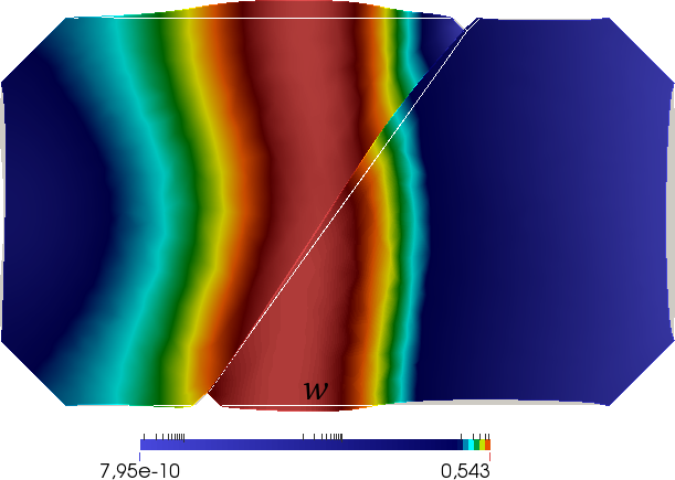
A second benchmark test, highlighting the role of the anisotropy induced by the activation dynamics, is performed on a square domain Ω0=[0,1]×[0,1]subscriptΩ00101\Omega_{0}=[0,1]\times[0,1] cm2. The Dirichlet part of the boundary is now represented by the bottom side of the domain, i.e., ΩD={(X1,X2):0X11,X2=0}subscriptΩ𝐷conditional-setsubscript𝑋1subscript𝑋2formulae-sequence0subscript𝑋11subscript𝑋20\partial\Omega_{D}=\{(X_{1},X_{2}):0\leq X_{1}\leq 1,X_{2}=0\}. The fiber vectors, defining the underlying cell microstructure, are in this case 𝒂l=(0,1)Tsubscript𝒂𝑙superscript01T{\boldsymbol{a}}_{l}=(0,1)^{\rm T}, 𝒂t=(1,0)Tsubscript𝒂𝑡superscript10T{\boldsymbol{a}}_{t}=(-1,0)^{\rm T}. The initial values for dimensionless electric potential and Calcium concentration are null everywhere but set in the active state V0=0.7subscript𝑉00.7V_{0}=0.7 and w0=0.2subscript𝑤00.2w_{0}=0.2 on the domain with X10.2subscript𝑋10.2X_{1}\leq 0.2 cm. These configuration is able to generate an action potential wave propagating from the bottom to the top of the domain. As expected [41], the electrical excitation wave induces a non-trivial contraction of the tissue due to the nonlinear coupling and the tissue anisotropy. According to experimental evidence, the maximum contraction of 20%percent2020\% of the resting length is recovered in the longitudinal direction. The deformed configuration at the peak of the activation variable γlsubscript𝛾𝑙\gamma_{l} is shown in Fig. 6(a) with the superimposed contour plot of the electric potential V𝑉V. Due to material incompressibility, thickening in the transverse direction is also observed. The corresponding evolution of the action potential wave (solid line) and of the activation variables (dashed lines) from the center of the domain is shown in Figure 6(b).

Refer to caption
(a) Deformed mesh at t=200𝑡200t=200 ms
Refer to caption
(b) Time evolution of the electrophysiological variables
Figure 6: (a) Undeformed (gray) and deformed (colored) domain at t=200𝑡200t=200 ms, with superimposed contour plot of the electric potential V𝑉V. (b) Time evolution of the dimensionless electric potential V𝑉V and of the activation variables γlsubscript𝛾𝑙\gamma_{l} and γtsubscript𝛾𝑡\gamma_{t}.

4 Formulation of cardiomyocytes electromechanical interaction model

4.1 Strong form of the electromechanical contact problem

Let the myocyte Ω1subscriptΩ1\Omega_{1} be surrounded by a continuum representing the extracellular matrix or by a second myocyte Ω2subscriptΩ2\Omega_{2}, see Fig. 1(a). In this framework, the single myocyte transfers tractions, electric signals and kinetic variables across its active interface boundary ΩC1=ΩC2=ΩCsubscriptsuperscriptΩ1𝐶subscriptsuperscriptΩ2𝐶subscriptΩ𝐶\partial\Omega^{1}_{C}=\partial\Omega^{2}_{C}=\partial\Omega_{C}, as experimentally observed in [36]. The proposed strategy to simulate this problem is to solve the electromechanical problem for myocyte 1 and then to transfer the quantities at the interface to the other myocyte during the same time step. This approach, which is a strategy typically used for fluid-structure interaction problems [49] and that is herein adopted for myocyte-myocyte contact, is prepared over the interface elements or contact elements for its easy parallelization. This will ensure the scalability of the approach for the study of contact simulations with multiple myocytes, which is the target of interest for understanding the emergence of collective properties [50] reflected into cardiac diseases.

In order to stimulate the myocyte-myocyte interaction, an external excitation current Iappsubscript𝐼appI_{\rm app} is applied to myocyte Ω1subscriptΩ1\Omega_{1} such that a propagating front passes from Ω1subscriptΩ1\Omega_{1} to Ω2subscriptΩ2\Omega_{2} via ΩCsubscriptΩ𝐶\partial\Omega_{C} (or viceversa by exciting Ω2subscriptΩ2\Omega_{2} first, without any loss of generality). The objective consists in finding displacements, pressures and electrophysiological quantities for Ω1subscriptΩ1\Omega_{1} and Ω2subscriptΩ2\Omega_{2} which are solution of the following system of differential equations and incompressibility conditions (k=1,2𝑘12k=1,2):

𝐏(𝒖k)𝐏subscript𝒖𝑘\displaystyle-\nabla\cdot{\mathbf{P}}({\boldsymbol{u}}_{k}) =𝟎,absent0\displaystyle=\mathbf{0}, (12a)
Jksubscript𝐽𝑘\displaystyle J_{k} =1,absent1\displaystyle=1, (12b)
tVk+1Jk(𝐅k1𝐃𝐅kTVk)I(Vk,wk)subscript𝑡subscript𝑉𝑘1subscript𝐽𝑘subscriptsuperscript𝐅1𝑘subscriptsuperscript𝐃𝐅T𝑘subscript𝑉𝑘𝐼subscript𝑉𝑘subscript𝑤𝑘\displaystyle\partial_{t}V_{k}+\dfrac{1}{J_{k}}\nabla\cdot\left(\mathbf{F}^{-1}_{k}\mathbf{D}\mathbf{F}^{-\rm T}_{k}\nabla V_{k}\right)-I(V_{k},w_{k}) =Iapp,absentsubscript𝐼app\displaystyle=I_{\rm app}, (12c)
dtwkH(Vk,wk)subscript𝑑𝑡subscript𝑤𝑘𝐻subscript𝑉𝑘subscript𝑤𝑘\displaystyle d_{t}w_{k}-H(V_{k},w_{k}) =0,absent0\displaystyle=0, (12d)

where 𝒖k,pksubscript𝒖𝑘subscript𝑝𝑘{\boldsymbol{u}}_{k},p_{k} are the displacement and pressure fields defined in ΩksubscriptΩ𝑘\Omega_{k} while vk,wksubscript𝑣𝑘subscript𝑤𝑘v_{k},w_{k} are the electric potential and Calcium concentration defined in Ωk×[0,T]subscriptΩ𝑘0𝑇\Omega_{k}\times[0,T].

Homogeneous displacement boundary conditions are prescribed on the Dirichlet portions of the domains ΩD,1subscriptΩ𝐷1\Omega_{D,1} and ΩD,2subscriptΩ𝐷2\Omega_{D,2}, see Fig. 7:

𝒖1=𝟎onΩD,1and𝒖2=𝟎onΩD,2.formulae-sequencesubscript𝒖10onsubscriptΩ𝐷1andsubscript𝒖20onsubscriptΩ𝐷2{\boldsymbol{u}}_{1}=\mathbf{0}\,\,\,\text{on}\,\,\,\partial\Omega_{D,1}\quad\text{and}\quad{\boldsymbol{u}}_{2}=\mathbf{0}\,\,\,\text{on}\,\,\,\partial\Omega_{D,2}\,.

In addition, we assume the two electromechanical domains exchange tractions and electrical signals through the common interface boundary ΩCsubscriptΩ𝐶\partial\Omega_{C}, which can be mathematical formulated as mixed boundary conditions:

{𝐏𝐧12+𝐓12=𝟎𝐏𝐧21+𝐓21=𝟎onΩC,cases𝐏subscript𝐧12subscript𝐓12absent0𝐏subscript𝐧21subscript𝐓21absent0onsubscriptΩ𝐶\begin{cases}\mathbf{P}\,\mathbf{n}_{12}+\mathbf{T}_{12}&=\mathbf{0}\\ \mathbf{P}\,\mathbf{n}_{21}+\mathbf{T}_{21}&=\mathbf{0}\end{cases}\quad\text{on}\quad\partial\Omega_{C}, (13)
{(𝐃V1)𝐧12+cDn(V1V2)=0(𝐃V2)𝐧21+cDn(V2V1)=0onΩC,cases𝐃subscript𝑉1subscript𝐧12𝑐subscript𝐷𝑛subscript𝑉1subscript𝑉20otherwise𝐃subscript𝑉2subscript𝐧21𝑐subscript𝐷𝑛subscript𝑉2subscript𝑉10otherwiseonsubscriptΩ𝐶\begin{cases}\nabla\cdot\left(\mathbf{D}\nabla V_{1}\right)\cdot\mathbf{n}_{12}+cD_{n}(V_{1}-V_{2})=0\\ \nabla\cdot\left(\mathbf{D}\nabla V_{2}\right)\cdot\mathbf{n}_{21}+cD_{n}(V_{2}-V_{1})=0\end{cases}\ \text{on}\quad\partial\Omega_{C}, (14)

implicitly assuming Neumann zero flux conditions for the Calcium concentration field w𝑤w according to the formulation proposed in the previous section. Here 𝐓=𝐓12=𝐓21𝐓subscript𝐓12subscript𝐓21\mathbf{T}=\mathbf{T}_{12}=-\mathbf{T}_{21} is the interface traction; 𝐧=𝐧12=𝐧21𝐧subscript𝐧12subscript𝐧21\mathbf{n}=\mathbf{n}_{12}=-\mathbf{n}_{21} and 𝐭=𝐭12=𝐭21𝐭subscript𝐭12subscript𝐭21\mathbf{t}=\mathbf{t}_{12}=-\mathbf{t}_{21} are the normal and tangential unit vectors at each point of the internal boundary ΩCsubscriptΩ𝐶\partial\Omega_{C}; ΔV=|V1V2|Δ𝑉subscript𝑉1subscript𝑉2\Delta V=|V_{1}-V_{2}| is the voltage gap (transjunctional voltage) between Ω1subscriptΩ1\Omega_{1} and Ω2subscriptΩ2\Omega_{2}; c𝑐c represents a so far corrective term introduced in the computational model and Dnsubscript𝐷𝑛D_{n} is the nonlinear contact conductance detailed in the next section.

The generalized boundary conditions (13) and (14) complete the structure-structure electromechanical interaction problem between two adjacent myocytes Ω1subscriptΩ1\Omega_{1}, Ω2subscriptΩ2\Omega_{2} and tacking place at the interface boundary ΩCsubscriptΩ𝐶\partial\Omega_{C}.

Refer to caption
Figure 7: Sketch of the mesh and the Dirichlet boundary conditions used in the numerical simulation for the electromechanical contact problem between two cardiomyocytes.

4.2 Nonlinear constitutive mechanical contact model

As far as the mechanical response of the interface is concerned, tractions exchanged at the interface must be continuous for equilibrium considerations [51] and are assumed to be functions of the relative displacements between the two myocytes. Experimental results based on atomic force microscopy [52, 53] clearly highlight the existence of a contact regime in compression, and of an adhesive response in traction which can be modeled as a nonlinear traction-separation constitutive relation in accordance with [54, 55, 56, 57]. To distinguish between the normal and tangential response at the interface, the relative displacements 𝒖1𝒖2subscript𝒖1subscript𝒖2{\boldsymbol{u}}_{1}-{\boldsymbol{u}}_{2} are projected along 𝐧𝐧\mathbf{n} and 𝐭𝐭\mathbf{t}, providing the normal and the tangential relative displacements defined as gn=(𝒖1𝒖2)𝐧subscript𝑔𝑛subscript𝒖1subscript𝒖2𝐧g_{n}=({\boldsymbol{u}}_{1}-{\boldsymbol{u}}_{2})\cdot\mathbf{n} and gt=(𝒖1𝒖2)𝐭subscript𝑔𝑡subscript𝒖1subscript𝒖2𝐭g_{t}=({\boldsymbol{u}}_{1}-{\boldsymbol{u}}_{2})\cdot\mathbf{t}, respectively. Accordingly, interface tractions are decomposed as 𝐓=Tn𝐧+Tt𝐭𝐓subscript𝑇𝑛𝐧subscript𝑇𝑡𝐭\mathbf{T}=T_{n}\mathbf{n}+T_{t}\mathbf{t}.

The normal component of the interface traction is a function of the interface opening gnsubscript𝑔𝑛g_{n}, considering a penalty model in compression (gn<0subscript𝑔𝑛0g_{n}<0) and a linear tension cut-off adhesive response in tension (0<gn<gn,max0subscript𝑔𝑛subscript𝑔𝑛max0<g_{n}<g_{n,{\rm max}}):

Tn={αgn,ifgn<0,Tn,max(gngn,max),if0<gn<gn,max0,ifgngn,max,subscript𝑇𝑛cases𝛼subscript𝑔𝑛ifsubscript𝑔𝑛0subscript𝑇𝑛maxsubscript𝑔𝑛subscript𝑔𝑛maxif0subscript𝑔𝑛subscript𝑔𝑛max0ifsubscript𝑔𝑛subscript𝑔𝑛maxT_{n}=\begin{cases}\alpha g_{n},\ &\ \text{if}\quad g_{n}<0,\\ T_{n,\rm max}\left(\dfrac{g_{n}}{g_{n,\rm max}}\right),\ &\ \text{if}\quad 0<g_{n}<g_{n,\rm max}\\ 0,\ &\ \text{if}\quad g_{n}\geq g_{n,\rm max},\end{cases} (15)

where gn,maxsubscript𝑔𝑛maxg_{n,\rm max} is the critical separation and Tn,maxsubscript𝑇𝑛maxT_{n,\rm max} is the peak adhesive strength based on experimental observations [52]. We can select gn,max=1subscript𝑔𝑛max1g_{n,\rm max}=1 μ𝜇\mum, Tn,max=1000subscript𝑇𝑛max1000T_{n,{\rm max}}=1000 kPa and α=1000𝛼1000\alpha=1000 kPa for myocytes.

The constitutive response in tangential direction is modeled as a regularized Coulomb-friction law [58] in compression:

Tt=ftanh(gtat)|Tn|,subscript𝑇𝑡𝑓subscript𝑔𝑡subscript𝑎𝑡subscript𝑇𝑛T_{t}=f\tanh\left(\dfrac{g_{t}}{a_{t}}\right)|T_{n}|\,, (16)

where f𝑓f denotes the local friction coefficient and atsubscript𝑎𝑡a_{t} is the regularization length scale [58]. For the present problem, we set μ=4𝜇4\mu=4 kPa, f=1𝑓1f=1 and at=1μmsubscript𝑎𝑡1𝜇ma_{t}=1\,\mu{\rm m}. In tension, tangential tractions are assumed to be negligible. Tractions Tnsubscript𝑇𝑛T_{n} and Ttsubscript𝑇𝑡T_{t} are shown in Figs. 8(a) and Fig. 8(b), respectively.

Refer to caption
Refer to caption
Figure 8: (a) Cohesive traction-separation law. (b) Friction law.

4.3 Nonlinear electric conductance

As far as the transfer of electric voltage and current across the interface ΩCsubscriptΩ𝐶\partial\Omega_{C} is concerned, it is assumed that the current flows solely in the direction normal to the interface. According to the experimental evidence [17], the contact flux is a nonlinear function of the transjunctional voltage gap in compression and it is vanishing in tension (see also [59] for similar modeling in the case of thermo-elasticity problems at interfaces). The phenomenological constitutive law for Dnsubscript𝐷𝑛D_{n} during contact is assumed to mimic the average steady-state conductivity measured in dual patch clamping experiments for cardiovascular cells [60]. This quantity has the dimensions of a conductance per unit interface length, i.e. μ𝜇\muS/μ𝜇\mum:

Dn=a1+a2(11+ea3a4ΔV11+ea3+a4ΔV),subscript𝐷𝑛subscript𝑎1subscript𝑎211superscript𝑒subscript𝑎3subscript𝑎4Δ𝑉11superscript𝑒subscript𝑎3subscript𝑎4Δ𝑉D_{n}=a_{1}+a_{2}\left(\dfrac{1}{1+e^{-a_{3}-a_{4}\Delta V}}-\dfrac{1}{1+e^{-a_{3}+a_{4}\Delta V}}\right)\,, (17)

where a1=0.2225subscript𝑎10.2225a_{1}=0.2225 μ𝜇\muS/μ𝜇\mum, a2=0.8subscript𝑎20.8a_{2}=0.8 μ𝜇\muS/μ𝜇\mum, a3=5subscript𝑎35a_{3}=5, a4=4.25subscript𝑎44.25a_{4}=4.25. The selected parameters induce 80% of variation in the transjunctional conductance with respect to a baseline value, a1subscript𝑎1a_{1} according to [60]. The constitutive prescription (17) is depicted in Fig. 9.

Refer to caption
Figure 9: Conductivity per unit interface length vs. the nondimensional transjunctional voltage ΔVΔ𝑉\Delta V.

5 Computational modeling of the structure-structure electromechanical interaction

The numerical algorithm for the structure-structure interaction problem between two cardiac myocytes is herein detailed and implemented via the open source software FreeFem++ [61]. Typically, contact problems like those in the present study could be solved using node-to-segment or segment-to-segment contact formulations [58]. Alternatively, since the pairing between the slave and the master segments does not change during the deformation process, interface elements could be used as well, as in [57].

However, in order to develop a solution scheme of easy parallelization which allows for large scale computations with several interacting myocytes, in this study we formulate the contact problem as a structure-structure interaction model. In this context, by exploiting a sequential (staggered) solution algebraic scheme, 4 nonlinear algebric systems, resulting from the introduction of the FE discretization have to be solved: one mechanical and one electrophysiological for myocytes 1 and one mechanical and one electrophysiological for myocytes 2. Coupling between the two myocytes is achived via the structure-structure boundary conditions in Eqs. (13) and (14). At each time step tn+1superscript𝑡𝑛1t^{n+1}, the following operations are made:

  1. 1.

    (M1) Solution of the mechanical problem for the myocyte 111. The superscript ()kn+1subscriptsuperscript𝑛1𝑘(\cdot)^{n+1}_{k} means evaluation in the current Newton-Raphson approximation. The output variables are the displacement field vector 𝒖1n+1subscriptsuperscript𝒖𝑛11{\boldsymbol{u}}^{n+1}_{1} and the hydrostatic pressure p1n+1subscriptsuperscript𝑝𝑛11p^{n+1}_{1}, which is a Lagrange multiplier arising from the imposition of the incompressibility constraint J1=1subscript𝐽11J_{1}=1. Let γl,1n+1subscriptsuperscript𝛾𝑛1𝑙1\gamma^{n+1}_{l,1} and γt,1n+1subscriptsuperscript𝛾𝑛1𝑡1\gamma^{n+1}_{t,1} be the activation variables computed according to Eq. (8) and (3). Given the values of the displacement field vector and pressure (𝒖1n,p1n)subscriptsuperscript𝒖𝑛1subscriptsuperscript𝑝𝑛1({\boldsymbol{u}}^{n}_{1},p^{n}_{1}), and the same quantities at the k𝑘k-th iteration of the Newton-Raphson scheme (𝒖1,kn+1,p1,kn+1)subscriptsuperscript𝒖𝑛11𝑘subscriptsuperscript𝑝𝑛11𝑘({\boldsymbol{u}}^{n+1}_{1,k},p^{n+1}_{1,k}) for the myocyte 1, and the value of the displacement 𝒖2nsubscriptsuperscript𝒖𝑛2{\boldsymbol{u}}^{n}_{2} for myocyte 2 at the previous converged iteration, the current normal and tangential gaps, gn,kn+1=(𝒖1,kn+1𝒖2n)𝐧subscriptsuperscript𝑔𝑛1𝑛𝑘subscriptsuperscript𝒖𝑛11𝑘subscriptsuperscript𝒖𝑛2𝐧g^{n+1}_{n,k}=({\boldsymbol{u}}^{n+1}_{1,k}-{\boldsymbol{u}}^{n}_{2})\cdot\mathbf{n} and gt,kn+1=(𝒖1,kn+1𝒖2n)𝐭subscriptsuperscript𝑔𝑛1𝑡𝑘subscriptsuperscript𝒖𝑛11𝑘subscriptsuperscript𝒖𝑛2𝐭g^{n+1}_{t,k}=({\boldsymbol{u}}^{n+1}_{1,k}-{\boldsymbol{u}}^{n}_{2})\cdot\mathbf{t}, and the cohesive traction vector 𝐓kn+1subscriptsuperscript𝐓𝑛1𝑘\mathbf{T}^{n+1}_{k} are computed. At each iteration k+1𝑘1k+1, the mechanical problem of contact between the two myocytes 111 and 222 consists in finding the correction in the displacement vector and pressure (δ𝒖1,δp1)𝛿subscript𝒖1𝛿subscript𝑝1(\delta{\boldsymbol{u}}_{1},\delta p_{1}) inside myocyte Ω1subscriptΩ1\Omega_{1} such that for all test functions (𝒗1,q1)subscript𝒗1subscript𝑞1({\boldsymbol{v}}_{1},q_{1}) are solutions of the following linearized system of equations, equipped with boundary conditions accounting for the stucture-structure interaction between myocytes Ω1subscriptΩ1\Omega_{1} and Ω2subscriptΩ2\Omega_{2} (Eqs. (15) and (16)) on the internal boundary ΩCsubscriptΩ𝐶\partial\Omega_{C}:

    1(𝒖1,kn+1,p1,kn+1;𝒖2n)(δ𝒖1,δp1)=Ω1μJ1,anδ𝐅1(𝐅1,an)1(𝐅1,an)T:𝒗1d𝑿1:subscript1subscriptsuperscript𝒖𝑛11𝑘subscriptsuperscript𝑝𝑛11𝑘subscriptsuperscript𝒖𝑛2𝛿subscript𝒖1𝛿subscript𝑝1subscriptsubscriptΩ1𝜇subscriptsuperscript𝐽𝑛1𝑎𝛿subscript𝐅1superscriptsubscriptsuperscript𝐅𝑛1𝑎1superscriptsubscriptsuperscript𝐅𝑛1𝑎Tlimit-fromsubscript𝒗1dsubscript𝑿1\displaystyle\mathcal{M}_{1}({\boldsymbol{u}}^{n+1}_{1,k},p^{n+1}_{1,k};{\boldsymbol{u}}^{n}_{2})(\delta{\boldsymbol{u}}_{1},\delta p_{1})=\int_{\Omega_{1}}\mu J^{n}_{1,a}\delta\mathbf{F}_{1}(\mathbf{F}^{n}_{1,a})^{-1}(\mathbf{F}^{n}_{1,a})^{-\rm T}:\nabla{\boldsymbol{v}}_{1}\;{\rm d}{\boldsymbol{X}}_{1}- (18)
    Ω1p1,kn+1Cof(δ𝐅1):𝒗1d𝑿1+Ω1J1,kn+1(𝐅1,kn+1)T:δ𝐅1q1d𝑿1Ω1J1,kn+1δp1(𝐅1,kn+1)T:𝒗1d𝑿1+:subscriptsubscriptΩ1subscriptsuperscript𝑝𝑛11𝑘Cof𝛿subscript𝐅1subscript𝒗1dsubscript𝑿1subscriptsubscriptΩ1subscriptsuperscript𝐽𝑛11𝑘superscriptsubscriptsuperscript𝐅𝑛11𝑘T:𝛿subscript𝐅1subscript𝑞1dsubscript𝑿1subscriptsubscriptΩ1subscriptsuperscript𝐽𝑛11𝑘𝛿subscript𝑝1superscriptsubscriptsuperscript𝐅𝑛11𝑘T:limit-fromsubscript𝒗1dsubscript𝑿1\displaystyle\int_{\Omega_{1}}p^{n+1}_{1,k}\text{Cof}(\delta\mathbf{F}_{1}):\nabla{\boldsymbol{v}}_{1}\;{\rm d}{\boldsymbol{X}}_{1}+\int_{\Omega_{1}}J^{n+1}_{1,k}(\mathbf{F}^{n+1}_{1,k})^{-\rm T}:\delta\mathbf{F}_{1}q_{1}\;{\rm d}{\boldsymbol{X}}_{1}-\int_{\Omega_{1}}J^{n+1}_{1,k}\delta p_{1}(\mathbf{F}^{n+1}_{1,k})^{-\rm T}:\nabla{\boldsymbol{v}}_{1}\;{\rm d}{\boldsymbol{X}}_{1}+
    ΩCδ𝒖1T𝐓kn+1𝒗1dΓ=R1,kn+1,𝒗1𝑽0,h,q1Q0,hformulae-sequencesubscriptsubscriptΩ𝐶𝛿subscriptsuperscript𝒖T1subscriptsuperscript𝐓𝑛1𝑘subscript𝒗1dΓsubscriptsuperscript𝑅𝑛11𝑘formulae-sequencefor-allsubscript𝒗1subscript𝑽0subscript𝑞1subscript𝑄0\displaystyle\int_{\partial\Omega_{C}}\delta{\boldsymbol{u}}^{\rm T}_{1}\nabla\mathbf{T}^{n+1}_{k}{\boldsymbol{v}}_{1}\;{\rm d}\Gamma=-R^{n+1}_{1,k},\quad\forall{\boldsymbol{v}}_{1}\in{\boldsymbol{V}}_{0,h},q_{1}\in Q_{0,h}

    where the notation δ𝐅1𝛿subscript𝐅1\delta{\mathbf{F}}_{1} stands for (δ𝒖1)𝛿subscript𝒖1\nabla(\delta{\boldsymbol{u}}_{1}), and Cof(𝐅1)Cofsubscript𝐅1\text{Cof}({\mathbf{F}}_{1}) is the cofactor operator applied to the deformation gradient 𝐅1subscript𝐅1{\mathbf{F}}_{1}, see Appendix A. For details on the spaces 𝑽0,hsubscript𝑽0{\boldsymbol{V}}_{0,h} and Q0,hsubscript𝑄0Q_{0,h}, see also Appendix A.

    Note that the last integral in Eq. (18) is defined on the internal boundary ΩCsubscriptΩ𝐶\partial\Omega_{C} and accounts for the traction 𝐓𝐓\mathbf{T} acting on myocyte Ω1subscriptΩ1\Omega_{1} due to the interaction with myocyte Ω2subscriptΩ2\Omega_{2}. The Jacobian of the traction vector 𝐓𝐓\nabla\mathbf{T}, needed in the linearization, is given by:

    𝐓=(TngnTngtTtgnTtgt).𝐓superscript𝑇𝑛subscript𝑔𝑛superscript𝑇𝑛subscript𝑔𝑡superscript𝑇𝑡subscript𝑔𝑛superscript𝑇𝑡subscript𝑔𝑡\nabla\mathbf{T}=\left(\begin{array}[]{cc}\dfrac{\partial T^{n}}{\partial g_{n}}&\dfrac{\partial T^{n}}{\partial g_{t}}\\ \dfrac{\partial T^{t}}{\partial g_{n}}&\dfrac{\partial T^{t}}{\partial g_{t}}\end{array}\right). (19)

    As a result, the residual R1,kn+1subscriptsuperscript𝑅𝑛11𝑘R^{n+1}_{1,k} is defined as:

    R1,kn+1(𝐮1,kn+1,p1,kn+1)=subscriptsuperscript𝑅𝑛11𝑘subscriptsuperscript𝐮𝑛11𝑘subscriptsuperscript𝑝𝑛11𝑘absent\displaystyle R^{n+1}_{1,k}(\mathbf{u}^{n+1}_{1,k},p^{n+1}_{1,k})= Ω1μJ1,an𝐅1,kn+1(𝐅1,an)1(𝐅1,an)T:𝒗1d𝑿1Ω1J1,kn+1p1,kn+1(𝐅1,kn+1)T:𝒗1d𝑿1+:subscriptsubscriptΩ1𝜇subscriptsuperscript𝐽𝑛1𝑎subscriptsuperscript𝐅𝑛11𝑘superscriptsubscriptsuperscript𝐅𝑛1𝑎1superscriptsubscriptsuperscript𝐅𝑛1𝑎Tsubscript𝒗1dsubscript𝑿1subscriptsubscriptΩ1subscriptsuperscript𝐽𝑛11𝑘subscriptsuperscript𝑝𝑛11𝑘superscriptsubscriptsuperscript𝐅𝑛11𝑘T:limit-fromsubscript𝒗1dsubscript𝑿1\displaystyle\int_{\Omega_{1}}\mu J^{n}_{1,a}\mathbf{F}^{n+1}_{1,k}(\mathbf{F}^{n}_{1,a})^{-1}(\mathbf{F}^{n}_{1,a})^{-\rm T}:\nabla{\boldsymbol{v}}_{1}\;{\rm d}{\boldsymbol{X}}_{1}-\int_{\Omega_{1}}J^{n+1}_{1,k}p^{n+1}_{1,k}(\mathbf{F}^{n+1}_{1,k})^{-\rm T}:\nabla{\boldsymbol{v}}_{1}\;{\rm d}{\boldsymbol{X}}_{1}+ (20)
    Ω1(J1,kn+11)q1d𝑿1+ΩC𝐓kn+1𝒗1dΓ.subscriptsubscriptΩ1subscriptsuperscript𝐽𝑛11𝑘1subscript𝑞1differential-dsubscript𝑿1subscriptsubscriptΩ𝐶subscriptsuperscript𝐓𝑛1𝑘subscript𝒗1differential-dΓ\displaystyle\int_{\Omega_{1}}(J^{n+1}_{1,k}-1)q_{1}\;{\rm d}{\boldsymbol{X}}_{1}+\int_{\partial\Omega_{C}}\mathbf{T}^{n+1}_{k}{\boldsymbol{v}}_{1}\;{\rm d}\Gamma.

    The last integral accounting for the contact between the two myocytes acts like a traction defined on the Neumann boundary ΩCsubscriptΩ𝐶\partial\Omega_{C}. The linearized system (18) is solved until the incremental norm:

    incrm=δ𝒖1𝐇1(Ω1)2𝒖1,kn+1𝐇1(Ω1)2+δp1L2(Ω1)2p1,kn+1L2(Ω1)2,subscriptincrmsubscriptsuperscriptnorm𝛿subscript𝒖12superscript𝐇1subscriptΩ1subscriptsuperscriptnormsubscriptsuperscript𝒖𝑛11𝑘2superscript𝐇1subscriptΩ1subscriptsuperscriptnorm𝛿subscript𝑝12superscript𝐿2subscriptΩ1subscriptsuperscriptnormsubscriptsuperscript𝑝𝑛11𝑘2superscript𝐿2subscriptΩ1{}{\rm incr_{m}}=\dfrac{\|\delta{\boldsymbol{u}}_{1}\|^{2}_{\mathbf{H}^{1}(\Omega_{1})}}{\|{\boldsymbol{u}}^{n+1}_{1,k}\|^{2}_{\mathbf{H}^{1}(\Omega_{1})}}+\dfrac{\|\delta p_{1}\|^{2}_{L^{2}(\Omega_{1})}}{\|p^{n+1}_{1,k}\|^{2}_{L^{2}(\Omega_{1})}}, (21)

    is less than a prescribed tolerance tolmsubscripttolm{\rm tol_{m}}.

    After convergence, the values of the displacement field 𝒖1n+1subscriptsuperscript𝒖𝑛11{\boldsymbol{u}}^{n+1}_{1} and pressure p1n+1subscriptsuperscript𝑝𝑛11p^{n+1}_{1} inside myocyte 1 are determined. The updated deformed domain Ω1n+1subscriptsuperscriptΩ𝑛11\Omega^{n+1}_{1} is now given by the coordinates 𝒙1n+1=𝒙1n+𝒖1n+1subscriptsuperscript𝒙𝑛11subscriptsuperscript𝒙𝑛1subscriptsuperscript𝒖𝑛11{\boldsymbol{x}}^{n+1}_{1}={\boldsymbol{x}}^{n}_{1}+{\boldsymbol{u}}^{n+1}_{1}.

  2. 2.

    (E1) Solution of the electrophysiological problem for the myocyte 111. Given the values of the electric potential V1nsubscriptsuperscript𝑉𝑛1V^{n}_{1} and Calcium concentration w1nsubscriptsuperscript𝑤𝑛1w^{n}_{1}, and the same quantities at the k𝑘k-th iteration of the Newton-Raphson scheme V1,kn+1subscriptsuperscript𝑉𝑛11𝑘V^{n+1}_{1,k} and w1,kn+1subscriptsuperscript𝑤𝑛11𝑘w^{n+1}_{1,k} for the myocyte 1, and the value of the electric potential V2nsubscriptsuperscript𝑉𝑛2V^{n}_{2} for myocyte 2 at the previous converged iteration, the current gap in electric potential ΔV=|V1n+1,kV2n|Δ𝑉subscriptsuperscript𝑉𝑛1𝑘1subscriptsuperscript𝑉𝑛2\Delta V=|V^{n+1,k}_{1}-V^{n}_{2}| and the current value Dn,kn+1subscriptsuperscript𝐷𝑛1𝑛𝑘D^{n+1}_{n,k} of the conductivity are computed. The electrophysiological problem consists in finding the corrections δV1𝛿subscript𝑉1\delta V_{1} and δw1𝛿subscript𝑤1\delta w_{1} inside the myocyte 111, such that for all test functions ξ1subscript𝜉1\xi_{1} and ϕ1subscriptitalic-ϕ1\phi_{1} are solutions of the following linearized reaction-diffusion system:

    1,V(V1,kn+1,w1,kn+1;V2n)(δV1,δw1)=1ΔtΩ1δV1ξ1d𝑿1+Ω1(𝐅1n+1)1𝐃(𝐅1n+1)TδV1ξ1d𝑿1subscript1𝑉subscriptsuperscript𝑉𝑛11𝑘subscriptsuperscript𝑤𝑛11𝑘subscriptsuperscript𝑉𝑛2𝛿subscript𝑉1𝛿subscript𝑤11Δ𝑡subscriptsubscriptΩ1𝛿subscript𝑉1subscript𝜉1differential-dsubscript𝑿1limit-fromsubscriptsubscriptΩ1superscriptsubscriptsuperscript𝐅𝑛111𝐃superscriptsubscriptsuperscript𝐅𝑛11T𝛿subscript𝑉1subscript𝜉1dsubscript𝑿1\displaystyle\mathcal{E}_{1,V}(V^{n+1}_{1,k},w^{n+1}_{1,k};V^{n}_{2})(\delta V_{1},\delta w_{1})=\dfrac{1}{\Delta t}\int_{\Omega_{1}}\delta V_{1}\xi_{1}\;{\rm d}{\boldsymbol{X}}_{1}+\int_{\Omega_{1}}(\mathbf{F}^{n+1}_{1})^{-1}\mathbf{D}(\mathbf{F}^{n+1}_{1})^{-\rm T}\nabla\delta V_{1}\cdot\nabla\xi_{1}\;{\rm d}{\boldsymbol{X}}_{1}-
    Ω1Ikn+1VδV1ξ1d𝑿Ω1Ikn+1wδw1ξ1d𝑿1+ΩCc(Dn,kn+1V(V1,kn+1V2n)+Dn,kn+1)δV1ξ1dΓsubscriptsubscriptΩ1subscriptsuperscript𝐼𝑛1𝑘𝑉𝛿subscript𝑉1subscript𝜉1differential-d𝑿subscriptsubscriptΩ1subscriptsuperscript𝐼𝑛1𝑘𝑤𝛿subscript𝑤1subscript𝜉1differential-dsubscript𝑿1subscriptsubscriptΩ𝐶𝑐subscriptsuperscript𝐷𝑛1𝑛𝑘𝑉subscriptsuperscript𝑉𝑛11𝑘subscriptsuperscript𝑉𝑛2subscriptsuperscript𝐷𝑛1𝑛𝑘𝛿subscript𝑉1subscript𝜉1differential-dΓ\displaystyle\int_{\Omega_{1}}\dfrac{\partial I^{n+1}_{k}}{\partial V}\delta V_{1}\xi_{1}\;{\rm d}{\boldsymbol{X}}-\int_{\Omega_{1}}\dfrac{\partial I^{n+1}_{k}}{\partial w}\delta w_{1}\xi_{1}\;{\rm d}{\boldsymbol{X}}_{1}+\int_{\partial\Omega_{C}}c\left(\dfrac{\partial D^{n+1}_{n,k}}{\partial V}(V^{n+1}_{1,k}-V^{n}_{2})+D^{n+1}_{n,k}\right)\delta V_{1}\xi_{1}\;{\rm d}\Gamma
    =R1,Vn+1,k,ξ1𝒱0,hformulae-sequenceabsentsubscriptsuperscript𝑅𝑛1𝑘1𝑉for-allsubscript𝜉1subscript𝒱0\displaystyle=-R^{n+1,k}_{1,V},\quad\forall\xi_{1}\in\mathcal{V}_{0,h} (22a)
    1,w(V1,kn+1,w1,kn+1)(δV1,δw1)=1ΔtΩ1δw1ϕ1d𝑿1Ω1Hkn+1Vδv1ϕ1d𝑿1Ω1Hkn+1wδw1ϕ1d𝑿1subscript1𝑤subscriptsuperscript𝑉𝑛11𝑘subscriptsuperscript𝑤𝑛11𝑘𝛿subscript𝑉1𝛿subscript𝑤11Δ𝑡subscriptsubscriptΩ1𝛿subscript𝑤1subscriptitalic-ϕ1differential-dsubscript𝑿1subscriptsubscriptΩ1subscriptsuperscript𝐻𝑛1𝑘𝑉𝛿subscript𝑣1subscriptitalic-ϕ1differential-dsubscript𝑿1subscriptsubscriptΩ1subscriptsuperscript𝐻𝑛1𝑘𝑤𝛿subscript𝑤1subscriptitalic-ϕ1differential-dsubscript𝑿1\displaystyle\mathcal{E}_{1,w}(V^{n+1}_{1,k},w^{n+1}_{1,k})(\delta V_{1},\delta w_{1})=\dfrac{1}{\Delta t}\int_{\Omega_{1}}\delta w_{1}\phi_{1}\;{\rm d}{\boldsymbol{X}}_{1}-\int_{\Omega_{1}}\dfrac{\partial H^{n+1}_{k}}{\partial V}\delta v_{1}\phi_{1}\;{\rm d}{\boldsymbol{X}}_{1}-\int_{\Omega_{1}}\dfrac{\partial H^{n+1}_{k}}{\partial w}\delta w_{1}\phi_{1}\;{\rm d}{\boldsymbol{X}}_{1}
    =R1,wn+1,k,ϕ1𝒲0,h,formulae-sequenceabsentsubscriptsuperscript𝑅𝑛1𝑘1𝑤for-allsubscriptitalic-ϕ1subscript𝒲0\displaystyle=-R^{n+1,k}_{1,w},\quad\forall\phi_{1}\in\mathcal{W}_{0,h}, (22b)

    obtained by using the Euler backward time stepping scheme. The integral defined on ΩCsubscriptΩ𝐶\partial\Omega_{C} in Eq.(22a) represents the linearization of the boundary condition for electric current across the boundary. The residual R1,Vn+1,ksubscriptsuperscript𝑅𝑛1𝑘1𝑉R^{n+1,k}_{1,V} for the equation for V𝑉V is given by:

    R1,Vn+1,k=subscriptsuperscript𝑅𝑛1𝑘1𝑉absent\displaystyle R^{n+1,k}_{1,V}= 1ΔtΩ1(V1,kn+1v1n)ξ1d𝑿1+Ω1(𝐅1n+1)1𝐃(𝐅1n+1)TV1,kn+1ξ1d𝑿1Ω1Ikn+1ξ1d𝑿1Δ𝑡subscriptsubscriptΩ1subscriptsuperscript𝑉𝑛11𝑘subscriptsuperscript𝑣𝑛1subscript𝜉1differential-dsubscript𝑿1subscriptsubscriptΩ1superscriptsubscriptsuperscript𝐅𝑛111𝐃superscriptsubscriptsuperscript𝐅𝑛11Tsubscriptsuperscript𝑉𝑛11𝑘subscript𝜉1dsubscript𝑿1limit-fromsubscriptsubscriptΩ1subscriptsuperscript𝐼𝑛1𝑘subscript𝜉1differential-d𝑿\displaystyle\dfrac{1}{\Delta t}\int_{\Omega_{1}}(V^{n+1}_{1,k}-v^{n}_{1})\xi_{1}\;{\rm d}{\boldsymbol{X}}_{1}+\int_{\Omega_{1}}(\mathbf{F}^{n+1}_{1})^{-1}\mathbf{D}(\mathbf{F}^{n+1}_{1})^{-\rm T}\nabla V^{n+1}_{1,k}\cdot\nabla\xi_{1}\;{\rm d}{\boldsymbol{X}}_{1}-\int_{\Omega_{1}}I^{n+1}_{k}\xi_{1}\;{\rm d}{\boldsymbol{X}}-
    Ω1Iappξ1d𝑿1+ΩCcDn,kn+1(V1,kn+1V2n)ξ1dΓ.subscriptsubscriptΩ1subscript𝐼appsubscript𝜉1differential-dsubscript𝑿1subscriptsubscriptΩ𝐶𝑐subscriptsuperscript𝐷𝑛1𝑛𝑘subscriptsuperscript𝑉𝑛11𝑘subscriptsuperscript𝑉𝑛2subscript𝜉1differential-dΓ\displaystyle\int_{\Omega_{1}}I_{\rm app}\xi_{1}\;{\rm d}{\boldsymbol{X}}_{1}+\int_{\partial\Omega_{C}}cD^{n+1}_{n,k}(V^{n+1}_{1,k}-V^{n}_{2})\xi_{1}\;{\rm d}\Gamma.

    Notice that the last integral accounting for the electric contact between the two myocytes, plays the role of an electric flux defined on the Neumann boundary ΩCsubscriptΩ𝐶\partial\Omega_{C}. The residual R1,wn+1,ksubscriptsuperscript𝑅𝑛1𝑘1𝑤R^{n+1,k}_{1,w} for the equation for w𝑤w is given by:

    R1,wn+1,k=1ΔtΩ1(w1,kn+1w1n)ϕ1d𝑿1Ω1Hkn+1ϕ1d𝑿1.subscriptsuperscript𝑅𝑛1𝑘1𝑤1Δ𝑡subscriptsubscriptΩ1subscriptsuperscript𝑤𝑛11𝑘subscriptsuperscript𝑤𝑛1subscriptitalic-ϕ1differential-dsubscript𝑿1subscriptsubscriptΩ1subscriptsuperscript𝐻𝑛1𝑘subscriptitalic-ϕ1differential-dsubscript𝑿1\displaystyle R^{n+1,k}_{1,w}=\dfrac{1}{\Delta t}\int_{\Omega_{1}}(w^{n+1}_{1,k}-w^{n}_{1})\phi_{1}\;{\rm d}{\boldsymbol{X}}_{1}-\int_{\Omega_{1}}H^{n+1}_{k}\phi_{1}\;{\rm d}{\boldsymbol{X}}_{1}. (23)

    For the derivation of the linearized reaction-diffesion syestem and the finite element approximating spaces 𝒱0,hsubscript𝒱0\mathcal{V}_{0,h} and 𝒲0,hsubscript𝒲0\mathcal{W}_{0,h}, see Appendix A.

    The linearized system (22) is solved untill the norm of the electrophysiological variables

    incre=δV1L2(Ω1)2+δw1L2(Ω1)2,subscriptincr𝑒subscriptsuperscriptnorm𝛿subscript𝑉12superscript𝐿2subscriptΩ1subscriptsuperscriptnorm𝛿subscript𝑤12superscript𝐿2subscriptΩ1\textrm{incr}_{e}=\|\delta V_{1}\|^{2}_{L^{2}(\Omega_{1})}+\|\delta w_{1}\|^{2}_{L^{2}(\Omega_{1})}, (24)

    is less than a prescribed tolerance tolesubscripttole{\rm tol_{\rm e}}.

  3. 3.

    (M2) Solution of the mechanical problem for the myocyte 222. Given the values of the displacement field vector and pressure (𝒖2n,p2n)subscriptsuperscript𝒖𝑛2subscriptsuperscript𝑝𝑛2({\boldsymbol{u}}^{n}_{2},p^{n}_{2}), and the same quantities at the k𝑘k-th iteration of the Newton-Raphson scheme (𝒖2,kn+1,p2,kn+1)subscriptsuperscript𝒖𝑛12𝑘subscriptsuperscript𝑝𝑛12𝑘({\boldsymbol{u}}^{n+1}_{2,k},p^{n+1}_{2,k}) for the myocyte 2, and the value of the displacement 𝒖1n+1subscriptsuperscript𝒖𝑛11{\boldsymbol{u}}^{n+1}_{1} for myocyte 1 calculated in (M1), the current normal and tangential gaps, gn,kn+1=(𝒖2,kn+1𝒖1n+1)𝐧subscriptsuperscript𝑔𝑛1𝑛𝑘subscriptsuperscript𝒖𝑛12𝑘subscriptsuperscript𝒖𝑛11𝐧g^{n+1}_{n,k}=({\boldsymbol{u}}^{n+1}_{2,k}-{\boldsymbol{u}}^{n+1}_{1})\cdot\mathbf{n} and gt,kn+1=(𝒖2,kn+1𝒖1n+1)𝐭subscriptsuperscript𝑔𝑛1𝑡𝑘subscriptsuperscript𝒖𝑛12𝑘subscriptsuperscript𝒖𝑛11𝐭g^{n+1}_{t,k}=({\boldsymbol{u}}^{n+1}_{2,k}-{\boldsymbol{u}}^{n+1}_{1})\cdot\mathbf{t}, and the cohesive traction vector 𝐓kn+1subscriptsuperscript𝐓𝑛1𝑘\mathbf{T}^{n+1}_{k} are computed. At each iteration k+1𝑘1k+1, the mechanical problem of contact between the two myocytes 111 and 222 consists in finding the correction in the displacement vector and pressure (δ𝒖2,δp2)𝛿subscript𝒖2𝛿subscript𝑝2(\delta{\boldsymbol{u}}_{2},\delta p_{2}) inside myocyte 222 such that for all test functions (𝒗2,q2)subscript𝒗2subscript𝑞2({\boldsymbol{v}}_{2},q_{2}) are solutions of the linearized system of equations analogous to (18):

    2(𝒖2,kn+1,p2,kn+1;𝒖1n+1)(δ𝒖2,δp2)=Ω2μJ2,anδ𝐅2(𝐅2,an)1(𝐅2,an)T:𝒗2d𝑿2:subscript2subscriptsuperscript𝒖𝑛12𝑘subscriptsuperscript𝑝𝑛12𝑘subscriptsuperscript𝒖𝑛11𝛿subscript𝒖2𝛿subscript𝑝2subscriptsubscriptΩ2𝜇subscriptsuperscript𝐽𝑛2𝑎𝛿subscript𝐅2superscriptsubscriptsuperscript𝐅𝑛2𝑎1superscriptsubscriptsuperscript𝐅𝑛2𝑎Tlimit-fromsubscript𝒗2dsubscript𝑿2\displaystyle\mathcal{M}_{2}({\boldsymbol{u}}^{n+1}_{2,k},p^{n+1}_{2,k};{\boldsymbol{u}}^{n+1}_{1})(\delta{\boldsymbol{u}}_{2},\delta p_{2})=\int_{\Omega_{2}}\mu J^{n}_{2,a}\delta\mathbf{F}_{2}(\mathbf{F}^{n}_{2,a})^{-1}(\mathbf{F}^{n}_{2,a})^{-\rm T}:\nabla{\boldsymbol{v}}_{2}\;{\rm d}{\boldsymbol{X}}_{2}- (25)
    Ω2p2,kn+1Cof(δ𝐅2):𝒗2d𝑿2+Ω2J2,kn+1(𝐅2,kn+1)T:δ𝐅2q2d𝑿2Ω2J2,kn+1δp1(𝐅2,kn+1)T:𝒗2d𝑿2+:subscriptsubscriptΩ2subscriptsuperscript𝑝𝑛12𝑘Cof𝛿subscript𝐅2subscript𝒗2dsubscript𝑿2subscriptsubscriptΩ2subscriptsuperscript𝐽𝑛12𝑘superscriptsubscriptsuperscript𝐅𝑛12𝑘T:𝛿subscript𝐅2subscript𝑞2dsubscript𝑿2subscriptsubscriptΩ2subscriptsuperscript𝐽𝑛12𝑘𝛿subscript𝑝1superscriptsubscriptsuperscript𝐅𝑛12𝑘T:limit-fromsubscript𝒗2dsubscript𝑿2\displaystyle\int_{\Omega_{2}}p^{n+1}_{2,k}\text{Cof}(\delta\mathbf{F}_{2}):\nabla{\boldsymbol{v}}_{2}\;{\rm d}{\boldsymbol{X}}_{2}+\int_{\Omega_{2}}J^{n+1}_{2,k}(\mathbf{F}^{n+1}_{2,k})^{-\rm T}:\delta\mathbf{F}_{2}q_{2}\;{\rm d}{\boldsymbol{X}}_{2}-\int_{\Omega_{2}}J^{n+1}_{2,k}\delta p_{1}(\mathbf{F}^{n+1}_{2,k})^{-\rm T}:\nabla{\boldsymbol{v}}_{2}\;{\rm d}{\boldsymbol{X}}_{2}+
    ΩCδ𝒖2T𝐓kn+1𝒗2dΓ=R2,kn+1,𝒗2𝑽0,h,q2Q0,hformulae-sequencesubscriptsubscriptΩ𝐶𝛿subscriptsuperscript𝒖T2subscriptsuperscript𝐓𝑛1𝑘subscript𝒗2dΓsubscriptsuperscript𝑅𝑛12𝑘formulae-sequencefor-allsubscript𝒗2subscript𝑽0subscript𝑞2subscript𝑄0\displaystyle\int_{\partial\Omega_{C}}\delta{\boldsymbol{u}}^{\rm T}_{2}\nabla\mathbf{T}^{n+1}_{k}{\boldsymbol{v}}_{2}\;{\rm d}\Gamma=-R^{n+1}_{2,k},\quad\forall{\boldsymbol{v}}_{2}\in{\boldsymbol{V}}_{0,h},q_{2}\in Q_{0,h}

    where the residual is now given by:

    R2,kn+1(𝐮2,kn+1,p2,kn+1)=subscriptsuperscript𝑅𝑛12𝑘subscriptsuperscript𝐮𝑛12𝑘subscriptsuperscript𝑝𝑛12𝑘absent\displaystyle R^{n+1}_{2,k}(\mathbf{u}^{n+1}_{2,k},p^{n+1}_{2,k})= Ω2μJ2,an𝐅2,kn+1(𝐅2,an)1(𝐅2,an)T:𝒗2d𝑿2Ω2J2,kn+1p2,kn+1(𝐅2,kn+1)T:𝒗2d𝑿2+:subscriptsubscriptΩ2𝜇subscriptsuperscript𝐽𝑛2𝑎subscriptsuperscript𝐅𝑛12𝑘superscriptsubscriptsuperscript𝐅𝑛2𝑎1superscriptsubscriptsuperscript𝐅𝑛2𝑎Tsubscript𝒗2dsubscript𝑿2subscriptsubscriptΩ2subscriptsuperscript𝐽𝑛12𝑘subscriptsuperscript𝑝𝑛12𝑘superscriptsubscriptsuperscript𝐅𝑛12𝑘T:limit-fromsubscript𝒗2dsubscript𝑿2\displaystyle\int_{\Omega_{2}}\mu J^{n}_{2,a}\mathbf{F}^{n+1}_{2,k}(\mathbf{F}^{n}_{2,a})^{-1}(\mathbf{F}^{n}_{2,a})^{-\rm T}:\nabla{\boldsymbol{v}}_{2}\;{\rm d}{\boldsymbol{X}}_{2}-\int_{\Omega_{2}}J^{n+1}_{2,k}p^{n+1}_{2,k}(\mathbf{F}^{n+1}_{2,k})^{-\rm T}:\nabla{\boldsymbol{v}}_{2}\;{\rm d}{\boldsymbol{X}}_{2}+ (26)
    Ω2(J2,kn+11)q2d𝑿2+ΩC𝐓kn+1𝒗2dΓ.subscriptsubscriptΩ2subscriptsuperscript𝐽𝑛12𝑘1subscript𝑞2differential-dsubscript𝑿2subscriptsubscriptΩ𝐶subscriptsuperscript𝐓𝑛1𝑘subscript𝒗2differential-dΓ\displaystyle\int_{\Omega_{2}}(J^{n+1}_{2,k}-1)q_{2}\;{\rm d}{\boldsymbol{X}}_{2}+\int_{\partial\Omega_{C}}\mathbf{T}^{n+1}_{k}{\boldsymbol{v}}_{2}\;{\rm d}\Gamma.

    The resulting system of equations defining the problem (M2) is solved iteratively until the incremental norm incrmsubscriptincrm{\rm\text{incr}_{m}} is less than a given tolerance tolmsubscripttolm{\rm tol_{m}}. The only difference in the equivalent system of equations for (M2) is the way in which the gaps and the traction are computed using the solution of the previous problem (M1). After convergence, the updated (deformed) domain Ω2n+1subscriptsuperscriptΩ𝑛12\Omega^{n+1}_{2} is now given by the coordinates 𝒙2n+1=𝒙2n+𝒖2n+1subscriptsuperscript𝒙𝑛12subscriptsuperscript𝒙𝑛2subscriptsuperscript𝒖𝑛12{\boldsymbol{x}}^{n+1}_{2}={\boldsymbol{x}}^{n}_{2}+{\boldsymbol{u}}^{n+1}_{2}

  4. 4.

    (E2) Solution of the electrophysiological problem for the myocyte 222. Given the values of the electric potential V2nsubscriptsuperscript𝑉𝑛2V^{n}_{2} and Calcium concentration w2nsubscriptsuperscript𝑤𝑛2w^{n}_{2}, and the same quantities at the k𝑘k-th iteration of the Newton-Raphson scheme V2,kn+1subscriptsuperscript𝑉𝑛12𝑘V^{n+1}_{2,k} and w2,kn+1subscriptsuperscript𝑤𝑛12𝑘w^{n+1}_{2,k} for the myocyte 2, and the value of the electric potential V1n+1subscriptsuperscript𝑉𝑛11V^{n+1}_{1} for myocyte 1 computed as solution of the problem (E1), the current gap in electric potential ΔV=|V2n+1,kV1n+1|Δ𝑉subscriptsuperscript𝑉𝑛1𝑘2subscriptsuperscript𝑉𝑛11\Delta V=|V^{n+1,k}_{2}-V^{n+1}_{1}| and the current value Dn,kn+1subscriptsuperscript𝐷𝑛1𝑛𝑘D^{n+1}_{n,k} of the conductivity are computed. The electrophysiological problem (E2) consists in finding the corrections δV2𝛿subscript𝑉2\delta V_{2} and δw2𝛿subscript𝑤2\delta w_{2} inside the myocyte 222, such that for all test functions ξ2subscript𝜉2\xi_{2} and ϕ2subscriptitalic-ϕ2\phi_{2} are solutions of the following linearized reaction-diffusion system:

    2,V(V2,kn+1,w2,kn+1;V1n+1)(δV2,δw2)=1ΔtΩ2δV2ξ2d𝑿2+Ω2(𝐅2n+1)1𝐃(𝐅2n+1)TδV2ξ2d𝑿2subscript2𝑉subscriptsuperscript𝑉𝑛12𝑘subscriptsuperscript𝑤𝑛12𝑘subscriptsuperscript𝑉𝑛11𝛿subscript𝑉2𝛿subscript𝑤21Δ𝑡subscriptsubscriptΩ2𝛿subscript𝑉2subscript𝜉2differential-dsubscript𝑿2limit-fromsubscriptsubscriptΩ2superscriptsubscriptsuperscript𝐅𝑛121𝐃superscriptsubscriptsuperscript𝐅𝑛12T𝛿subscript𝑉2subscript𝜉2dsubscript𝑿2\displaystyle\mathcal{E}_{2,V}(V^{n+1}_{2,k},w^{n+1}_{2,k};V^{n+1}_{1})(\delta V_{2},\delta w_{2})=\dfrac{1}{\Delta t}\int_{\Omega_{2}}\delta V_{2}\xi_{2}\;{\rm d}{\boldsymbol{X}}_{2}+\int_{\Omega_{2}}(\mathbf{F}^{n+1}_{2})^{-1}\mathbf{D}(\mathbf{F}^{n+1}_{2})^{-\rm T}\nabla\delta V_{2}\cdot\nabla\xi_{2}\;{\rm d}{\boldsymbol{X}}_{2}-
    Ω2Ikn+1VδV2ξ2d𝑿2Ω2Ikn+1wδw2ξ2d𝑿2+ΩCc(Dn,kn+1V(V2,kn+1V1n+1)+Dn,kn+1)δV2ξ2dΓsubscriptsubscriptΩ2subscriptsuperscript𝐼𝑛1𝑘𝑉𝛿subscript𝑉2subscript𝜉2differential-dsubscript𝑿2subscriptsubscriptΩ2subscriptsuperscript𝐼𝑛1𝑘𝑤𝛿subscript𝑤2subscript𝜉2differential-dsubscript𝑿2subscriptsubscriptΩ𝐶𝑐subscriptsuperscript𝐷𝑛1𝑛𝑘𝑉subscriptsuperscript𝑉𝑛12𝑘subscriptsuperscript𝑉𝑛11subscriptsuperscript𝐷𝑛1𝑛𝑘𝛿subscript𝑉2subscript𝜉2differential-dΓ\displaystyle\int_{\Omega_{2}}\dfrac{\partial I^{n+1}_{k}}{\partial V}\delta V_{2}\xi_{2}\;{\rm d}{\boldsymbol{X}}_{2}-\int_{\Omega_{2}}\dfrac{\partial I^{n+1}_{k}}{\partial w}\delta w_{2}\xi_{2}\;{\rm d}{\boldsymbol{X}}_{2}+\int_{\partial\Omega_{C}}c\left(\dfrac{\partial D^{n+1}_{n,k}}{\partial V}(V^{n+1}_{2,k}-V^{n+1}_{1})+D^{n+1}_{n,k}\right)\delta V_{2}\xi_{2}\;{\rm d}\Gamma
    =R2,Vn+1,k,ξ2𝒱0,hformulae-sequenceabsentsubscriptsuperscript𝑅𝑛1𝑘2𝑉for-allsubscript𝜉2subscript𝒱0\displaystyle=-R^{n+1,k}_{2,V},\quad\forall\xi_{2}\in\mathcal{V}_{0,h} (27a)
    2,w(V2,kn+1,w2,kn+1)(δV2,δw2)=1ΔtΩ2δw2ϕ2d𝑿2Ω2Hkn+1VδV2ϕ2d𝑿2Ω2Hkn+1wδw2ϕ2d𝑿2subscript2𝑤subscriptsuperscript𝑉𝑛12𝑘subscriptsuperscript𝑤𝑛12𝑘𝛿subscript𝑉2𝛿subscript𝑤21Δ𝑡subscriptsubscriptΩ2𝛿subscript𝑤2subscriptitalic-ϕ2differential-dsubscript𝑿2subscriptsubscriptΩ2subscriptsuperscript𝐻𝑛1𝑘𝑉𝛿subscript𝑉2subscriptitalic-ϕ2differential-dsubscript𝑿2subscriptsubscriptΩ2subscriptsuperscript𝐻𝑛1𝑘𝑤𝛿subscript𝑤2subscriptitalic-ϕ2differential-dsubscript𝑿2\displaystyle\mathcal{E}_{2,w}(V^{n+1}_{2,k},w^{n+1}_{2,k})(\delta V_{2},\delta w_{2})=\dfrac{1}{\Delta t}\int_{\Omega_{2}}\delta w_{2}\phi_{2}\;{\rm d}{\boldsymbol{X}}_{2}-\int_{\Omega_{2}}\dfrac{\partial H^{n+1}_{k}}{\partial V}\delta V_{2}\phi_{2}\;{\rm d}{\boldsymbol{X}}_{2}-\int_{\Omega_{2}}\dfrac{\partial H^{n+1}_{k}}{\partial w}\delta w_{2}\phi_{2}\;{\rm d}{\boldsymbol{X}}_{2}
    =R2,wn+1,k,ϕ2𝒲0,h,formulae-sequenceabsentsubscriptsuperscript𝑅𝑛1𝑘2𝑤for-allsubscriptitalic-ϕ2subscript𝒲0\displaystyle=-R^{n+1,k}_{2,w},\quad\forall\phi_{2}\in\mathcal{W}_{0,h}, (27b)

    where the residual R2,Vn+1,ksubscriptsuperscript𝑅𝑛1𝑘2𝑉R^{n+1,k}_{2,V} for the equation for V𝑉V is given by:

    R2,Vn+1,k=subscriptsuperscript𝑅𝑛1𝑘2𝑉absent\displaystyle R^{n+1,k}_{2,V}= 1ΔtΩ2(V2,kn+1v2n)ξ2d𝑿2+Ω2(𝐅2n+1)1𝐃(𝐅2n+1)TV2,kn+1ξ2d𝑿2Ω2Ikn+1ξ2d𝑿2+1Δ𝑡subscriptsubscriptΩ2subscriptsuperscript𝑉𝑛12𝑘subscriptsuperscript𝑣𝑛2subscript𝜉2differential-dsubscript𝑿2subscriptsubscriptΩ2superscriptsubscriptsuperscript𝐅𝑛121𝐃superscriptsubscriptsuperscript𝐅𝑛12Tsubscriptsuperscript𝑉𝑛12𝑘subscript𝜉2dsubscript𝑿2limit-fromsubscriptsubscriptΩ2subscriptsuperscript𝐼𝑛1𝑘subscript𝜉2differential-dsubscript𝑿2\displaystyle\dfrac{1}{\Delta t}\int_{\Omega_{2}}(V^{n+1}_{2,k}-v^{n}_{2})\xi_{2}\;{\rm d}{\boldsymbol{X}}_{2}+\int_{\Omega_{2}}(\mathbf{F}^{n+1}_{2})^{-1}\mathbf{D}(\mathbf{F}^{n+1}_{2})^{-\rm T}\nabla V^{n+1}_{2,k}\cdot\nabla\xi_{2}\;{\rm d}{\boldsymbol{X}}_{2}-\int_{\Omega_{2}}I^{n+1}_{k}\xi_{2}\;{\rm d}{\boldsymbol{X}}_{2}+
    ΩCcDn,kn+1(V2,kn+1V1n+1)ξ2dΓ.subscriptsubscriptΩ𝐶𝑐subscriptsuperscript𝐷𝑛1𝑛𝑘subscriptsuperscript𝑉𝑛12𝑘subscriptsuperscript𝑉𝑛11subscript𝜉2differential-dΓ\displaystyle\int_{\partial\Omega_{C}}cD^{n+1}_{n,k}(V^{n+1}_{2,k}-V^{n+1}_{1})\xi_{2}\;{\rm d}\Gamma.

    and the residual R2,wn+1,ksubscriptsuperscript𝑅𝑛1𝑘2𝑤R^{n+1,k}_{2,w} for the equation for w2subscript𝑤2w_{2} is given by:

    R2,wn+1,k=1ΔtΩ2(w2,kn+1w2n)ϕ2d𝑿2Ω2Hkn+1ϕ2d𝑿2.subscriptsuperscript𝑅𝑛1𝑘2𝑤1Δ𝑡subscriptsubscriptΩ2subscriptsuperscript𝑤𝑛12𝑘subscriptsuperscript𝑤𝑛2subscriptitalic-ϕ2differential-dsubscript𝑿2subscriptsubscriptΩ2subscriptsuperscript𝐻𝑛1𝑘subscriptitalic-ϕ2differential-dsubscript𝑿2\displaystyle R^{n+1,k}_{2,w}=\dfrac{1}{\Delta t}\int_{\Omega_{2}}(w^{n+1}_{2,k}-w^{n}_{2})\phi_{2}\;{\rm d}{\boldsymbol{X}}_{2}-\int_{\Omega_{2}}H^{n+1}_{k}\phi_{2}\;{\rm d}{\boldsymbol{X}}_{2}. (28)

    The resulting system of equations defining problem (E2) is solved iteratively until the incremental norm incresubscriptincre{\rm\text{incr}_{e}} is less than a given tolerance tolesubscripttole{\rm tol_{e}}. The only difference in the equivalent system of equations for (E2) is the way in which the transjunctional gaps and the conductivities are computed using the solution of the previous problem (E1).

At each timestep, the described sequence of subproblems (M1), (E1), (M2) and (E2) is iterated until convergence of the physical interface conditions defined on ΩCsubscriptΩ𝐶\partial\Omega_{C}:

|gnn+1gnn+1,l||gnn+1|<tolp,gnn+1,l+1gnn+1,formulae-sequencesuperscriptsubscript𝑔𝑛𝑛1superscriptsubscript𝑔𝑛𝑛1𝑙superscriptsubscript𝑔𝑛𝑛1subscripttol𝑝superscriptsubscript𝑔𝑛𝑛1𝑙1superscriptsubscript𝑔𝑛𝑛1\displaystyle\dfrac{|g_{n}^{n+1}-g_{n}^{n+1,l}|}{|g_{n}^{n+1}|}<{\rm tol}_{p}\,,\quad g_{n}^{n+1,l+1}\leftarrow g_{n}^{n+1}\,, (29a)
|gtn+1gtn+1,l||gtn+1|<tolp,gtn+1,l+1gtn+1,formulae-sequencesuperscriptsubscript𝑔𝑡𝑛1superscriptsubscript𝑔𝑡𝑛1𝑙superscriptsubscript𝑔𝑡𝑛1subscripttol𝑝superscriptsubscript𝑔𝑡𝑛1𝑙1superscriptsubscript𝑔𝑡𝑛1\displaystyle\dfrac{|g_{t}^{n+1}-g_{t}^{n+1,l}|}{|g_{t}^{n+1}|}<{\rm tol}_{p}\,,\quad g_{t}^{n+1,l+1}\leftarrow g_{t}^{n+1}\,, (29b)
|ΔVn+1ΔVn+1,l||ΔVn+1|<tolp,ΔVn+1,l+1ΔVn+1,formulae-sequenceΔsuperscript𝑉𝑛1Δsuperscript𝑉𝑛1𝑙Δsuperscript𝑉𝑛1subscripttol𝑝Δsuperscript𝑉𝑛1𝑙1Δsuperscript𝑉𝑛1\displaystyle\dfrac{|\Delta V^{n+1}-\Delta V^{n+1,l}|}{|\Delta V^{n+1}|}<{\rm tol}_{p}\,,\quad\Delta V^{n+1,l+1}\leftarrow\Delta V^{n+1}\,, (29c)

where tol=p105{}_{p}=10^{-5}. This physical interface condition is denoted as (P). The algorithm for the proposed time integration with a staggered scheme is detailed in Algorithm 1.

Input mechanical parameters: μ,𝐚l,𝐚t,Tn,max,gn,max,f,at,α𝜇subscript𝐚𝑙subscript𝐚𝑡subscript𝑇𝑛maxsubscript𝑔𝑛max𝑓subscript𝑎𝑡𝛼\mu,\mathbf{a}_{l},\mathbf{a}_{t},T_{n,\rm max},g_{n,\rm max},f,a_{t},\alpha;
Input electrophysiological parameters: a,b,c1,c2,d,Dl,Dt,Iapp,a1,a2,a3,a4,c𝑎𝑏subscript𝑐1subscript𝑐2𝑑subscript𝐷𝑙subscript𝐷𝑡subscript𝐼appsubscript𝑎1subscript𝑎2subscript𝑎3subscript𝑎4𝑐a,b,c_{1},c_{2},d,D_{l},D_{t},I_{\rm app},a_{1},a_{2},a_{3},a_{4},c ;
Input activation: βc,c0,c,g0max,ϵsubscript𝛽𝑐subscript𝑐0superscript𝑐subscriptsuperscript𝑔max0italic-ϵ\beta_{c},c_{0},c^{*},g^{\rm max}_{0},\epsilon ;
for n=1,,Nit𝑛1subscript𝑁itn=1,\dots,N_{\rm it} timestepstimesteps\mathrm{time\ steps} do
       while the physical conditions at the interface (P) are not satisfied  do
             Compute 𝒖1n+1subscriptsuperscript𝒖𝑛11{\boldsymbol{u}}^{n+1}_{1} and p1n+1subscriptsuperscript𝑝𝑛11p^{n+1}_{1} solving the mechanical subproblem (M1) with value at the iterface 𝒖2nsubscriptsuperscript𝒖𝑛2{\boldsymbol{u}}^{n}_{2} ;
             while (incrmtolm)subscriptincrmsubscripttol𝑚(\mathrm{incr_{m}}\geq\mathrm{tol}_{m}) do
                   1(𝒖1,kn+1,p1,kn+1;𝒖2n)(δ𝒖1,δp1)=R1,kn+1subscript1subscriptsuperscript𝒖𝑛11𝑘subscriptsuperscript𝑝𝑛11𝑘subscriptsuperscript𝒖𝑛2𝛿subscript𝒖1𝛿subscript𝑝1subscriptsuperscript𝑅𝑛11𝑘\mathcal{M}_{1}({\boldsymbol{u}}^{n+1}_{1,k},p^{n+1}_{1,k};{\boldsymbol{u}}^{n}_{2})(\delta{\boldsymbol{u}}_{1},\delta p_{1})=-R^{n+1}_{1,k} ;
                   𝒖1,k+1n+1𝒖1,kn+1+δ𝒖1n+1subscriptsuperscript𝒖𝑛11𝑘1subscriptsuperscript𝒖𝑛11𝑘𝛿subscriptsuperscript𝒖𝑛11{\boldsymbol{u}}^{n+1}_{1,k+1}\leftarrow{\boldsymbol{u}}^{n+1}_{1,k}+\delta{\boldsymbol{u}}^{n+1}_{1} , p1,k+1n+1p1,kn+1+δp1n+1subscriptsuperscript𝑝𝑛11𝑘1subscriptsuperscript𝑝𝑛11𝑘𝛿subscriptsuperscript𝑝𝑛11p^{n+1}_{1,k+1}\leftarrow p^{n+1}_{1,k}+\delta p^{n+1}_{1};
                  
             end while
             Compute V1n+1subscriptsuperscript𝑉𝑛11V^{n+1}_{1} and w1n+1subscriptsuperscript𝑤𝑛11w^{n+1}_{1} solving the electrophysiological subproblem (E1) with value at the iterface V2nsubscriptsuperscript𝑉𝑛2V^{n}_{2} ;
             while (incretole)subscriptincr𝑒subscripttol𝑒(\mathrm{incr}_{e}\geq\mathrm{tol}_{e}) do
                  
{1,V(V1,kn+1,w1,kn+1;V2n)(δV1,δw1)=R1,Vn+11,w(V1,kn+1,w1,kn+1)(δV1,δw1)=R1,wn+1casessubscript1𝑉subscriptsuperscript𝑉𝑛11𝑘subscriptsuperscript𝑤𝑛11𝑘subscriptsuperscript𝑉𝑛2𝛿subscript𝑉1𝛿subscript𝑤1subscriptsuperscript𝑅𝑛11𝑉otherwisesubscript1𝑤subscriptsuperscript𝑉𝑛11𝑘subscriptsuperscript𝑤𝑛11𝑘𝛿subscript𝑉1𝛿subscript𝑤1subscriptsuperscript𝑅𝑛11𝑤otherwise\begin{cases}\mathcal{E}_{1,V}(V^{n+1}_{1,k},w^{n+1}_{1,k};V^{n}_{2})(\delta V_{1},\delta w_{1})=-R^{n+1}_{1,V}\\ \mathcal{E}_{1,w}(V^{n+1}_{1,k},w^{n+1}_{1,k})(\delta V_{1},\delta w_{1})=-R^{n+1}_{1,w}\end{cases}
V1,k+1n+1V1,kn+1+δV1n+1subscriptsuperscript𝑉𝑛11𝑘1subscriptsuperscript𝑉𝑛11𝑘𝛿subscriptsuperscript𝑉𝑛11V^{n+1}_{1,k+1}\leftarrow V^{n+1}_{1,k}+\delta V^{n+1}_{1} , w1,k+1n+1w1,kn+1+δw1n+1subscriptsuperscript𝑤𝑛11𝑘1subscriptsuperscript𝑤𝑛11𝑘𝛿subscriptsuperscript𝑤𝑛11w^{n+1}_{1,k+1}\leftarrow w^{n+1}_{1,k}+\delta w^{n+1}_{1};
                  
             end while
            Compute 𝒖2n+1subscriptsuperscript𝒖𝑛12{\boldsymbol{u}}^{n+1}_{2} and p2n+1subscriptsuperscript𝑝𝑛12p^{n+1}_{2} solving the mechanical subproblem (M2) with value at the iterface 𝒖1n+1subscriptsuperscript𝒖𝑛11{\boldsymbol{u}}^{n+1}_{1} ;
             while (incrmtolm)subscriptincrmsubscripttol𝑚(\mathrm{incr_{m}}\geq\mathrm{tol}_{m}) do
                   2(𝒖2,kn+1,p2,kn+1;𝒖1n+1)(δ𝒖2,δp2)=R2,kn+1subscript2subscriptsuperscript𝒖𝑛12𝑘subscriptsuperscript𝑝𝑛12𝑘subscriptsuperscript𝒖𝑛11𝛿subscript𝒖2𝛿subscript𝑝2subscriptsuperscript𝑅𝑛12𝑘\mathcal{M}_{2}({\boldsymbol{u}}^{n+1}_{2,k},p^{n+1}_{2,k};{\boldsymbol{u}}^{n+1}_{1})(\delta{\boldsymbol{u}}_{2},\delta p_{2})=-R^{n+1}_{2,k} ;
                   𝒖2,k+1n+1𝒖2,kn+1+δ𝒖2n+1subscriptsuperscript𝒖𝑛12𝑘1subscriptsuperscript𝒖𝑛12𝑘𝛿subscriptsuperscript𝒖𝑛12{\boldsymbol{u}}^{n+1}_{2,k+1}\leftarrow{\boldsymbol{u}}^{n+1}_{2,k}+\delta{\boldsymbol{u}}^{n+1}_{2} , p2,k+1n+1p2,kn+1+δp2n+1subscriptsuperscript𝑝𝑛12𝑘1subscriptsuperscript𝑝𝑛12𝑘𝛿subscriptsuperscript𝑝𝑛12p^{n+1}_{2,k+1}\leftarrow p^{n+1}_{2,k}+\delta p^{n+1}_{2};
                  
             end while
            Compute V2n+1subscriptsuperscript𝑉𝑛12V^{n+1}_{2} and w2n+1subscriptsuperscript𝑤𝑛12w^{n+1}_{2} solving the electrophysiological subproblem (E2) with value at the iterface V1n+1subscriptsuperscript𝑉𝑛11V^{n+1}_{1} ;
             while (incretole)subscriptincr𝑒subscripttol𝑒(\mathrm{incr}_{e}\geq\mathrm{tol}_{e}) do
                  
{2,V(V2,kn+1,w2,kn+1;V1n+1)(δV2,δw2)=R2,Vn+12,w(V2,kn+1,w2,kn+1)(δV2,δw2)=R2,wn+1casessubscript2𝑉subscriptsuperscript𝑉𝑛12𝑘subscriptsuperscript𝑤𝑛12𝑘subscriptsuperscript𝑉𝑛11𝛿subscript𝑉2𝛿subscript𝑤2subscriptsuperscript𝑅𝑛12𝑉otherwisesubscript2𝑤subscriptsuperscript𝑉𝑛12𝑘subscriptsuperscript𝑤𝑛12𝑘𝛿subscript𝑉2𝛿subscript𝑤2subscriptsuperscript𝑅𝑛12𝑤otherwise\begin{cases}\mathcal{E}_{2,V}(V^{n+1}_{2,k},w^{n+1}_{2,k};V^{n+1}_{1})(\delta V_{2},\delta w_{2})=-R^{n+1}_{2,V}\\ \mathcal{E}_{2,w}(V^{n+1}_{2,k},w^{n+1}_{2,k})(\delta V_{2},\delta w_{2})=-R^{n+1}_{2,w}\end{cases}
V2,k+1n+1V2,kn+1+δV2n+1subscriptsuperscript𝑉𝑛12𝑘1subscriptsuperscript𝑉𝑛12𝑘𝛿subscriptsuperscript𝑉𝑛12V^{n+1}_{2,k+1}\leftarrow V^{n+1}_{2,k}+\delta V^{n+1}_{2} , w2,k+1n+1w2,kn+1+δw2n+1subscriptsuperscript𝑤𝑛12𝑘1subscriptsuperscript𝑤𝑛12𝑘𝛿subscriptsuperscript𝑤𝑛12w^{n+1}_{2,k+1}\leftarrow w^{n+1}_{2,k}+\delta w^{n+1}_{2};
                  
             end while
            
       end while
      
end for
Algorithm 1 Numerical scheme for the solution of the structure-structure interaction problem for the electromechanical contact of two cardiomyocytes.

6 Numerical experiments

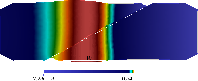
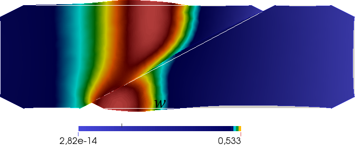
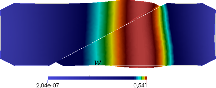
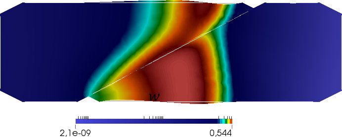
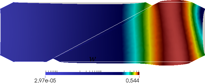
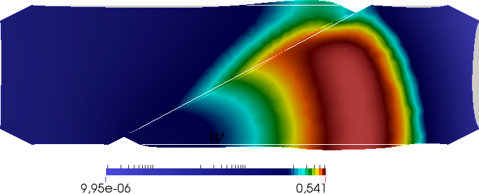
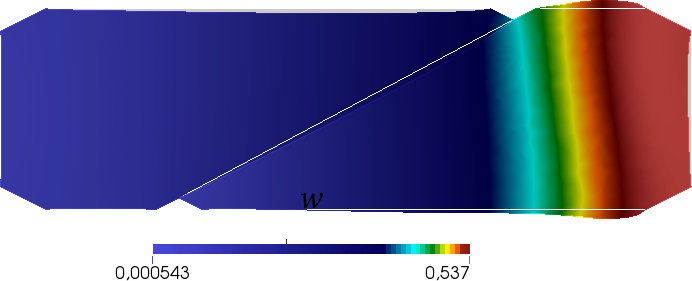
Several numerical examples are herein conducted in order to investigate the mechanical and electro-physiological responses of the interaction problem between cardiomyocytes for different test geometries and different values of the model parameters. Action potential diffusivities are scaled to the myocytes length scale such to reproduce a slow Calcium wave propagating behavior as in [30], i.e. Dl=Dt=0.06subscript𝐷𝑙subscript𝐷𝑡0.06D_{l}=D_{t}=0.06 μ𝜇\mum2/ms.

6.1 Myocyte geometry model

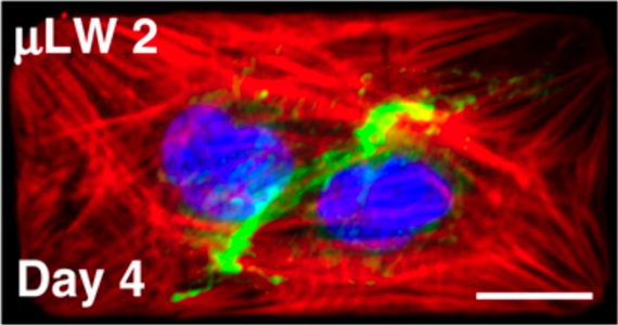
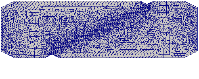
The geometry, boundary conditions and mesh discretization adopted for the numerical simulations are provided in Fig. 10. The vectors defining the fibers orientations are chosen as the unit vectors of the orthonormal basis of 2superscript2\mathbb{R}^{2}, i.e., 𝒂l=𝒆1subscript𝒂𝑙subscript𝒆1{\boldsymbol{a}}_{l}={\boldsymbol{e}}_{1} and 𝒂t=𝒆2subscript𝒂𝑡subscript𝒆2{\boldsymbol{a}}_{t}={\boldsymbol{e}}_{2}. With reference to Fig. 7, let L𝐿L and H𝐻H be, respectively, the sizes of the domain Ω1Ω2subscriptΩ1subscriptΩ2\Omega_{1}\cup\Omega_{2}. Myocytes are assumed to have the same material parameters.

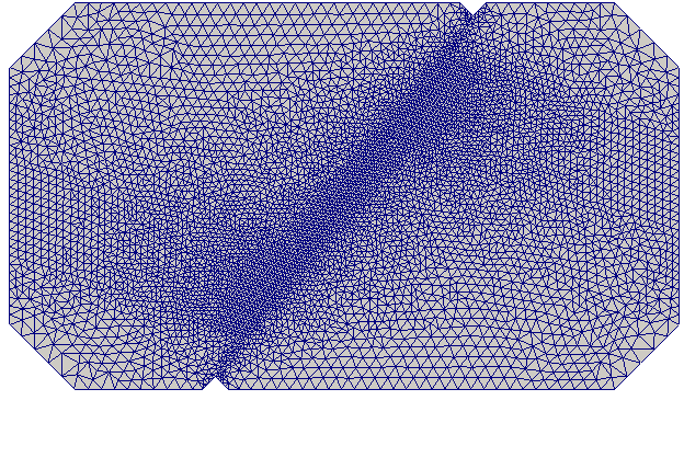
An electrical stimulus Iapp=exp(10(X12+(X2H/2)2))subscript𝐼app10subscriptsuperscript𝑋21superscriptsubscript𝑋2𝐻22I_{\rm app}=\exp(-10(X^{2}_{1}+(X_{2}-H/2)^{2})) is applied for a time interval [0,2]02[0,2] ms to myocyte 1 on a patch near its left boundary, centered in its middle position. This stimulation elicits the onset of an action potential wave propagating from myocyte 1 to myocyte 2 passing through the interface ΩCsubscriptΩ𝐶\partial\Omega_{C}. In order to asses how the inclination of the interface ΩCsubscriptΩ𝐶\partial\Omega_{C} with respect to the orientation of the longitudinal fiber vectors 𝒂lsubscript𝒂𝑙{\boldsymbol{a}}_{l} affects the propagation of electrical waves, we consider different values of L𝐿L and H𝐻H. Correspondingly, we define three aspect ratios AR1, AR2, AR3 defined by the ratio L/H=52/26,72/18,112/14𝐿𝐻5226721811214L/H=52/26,72/18,112/14 [μm/μm]delimited-[]𝜇m𝜇m[\mu{\rm m}/\mu{\rm m}], as in experimental μ𝜇\mu-engineered cell cultures [36]. Accordingly, three lengths of the interface ΩCsubscriptΩ𝐶\partial\Omega_{C} are obtained: 24,26242624,26, and 38μm38𝜇m38\;\mu\rm m for AR1, AR2 and AR3, respectively. These three geometries corresponding to their own aspect ratios shown in Fig.  10 are observed in different temporal stages of cardiomyocyte differentiation, namely at four days of tissue development. In all the numerical simulations a refinement of the mesh is adopted on the interface boundary ΩCsubscriptΩ𝐶\partial\Omega_{C}. Unstructured triangular meshes are considered containing 11308,9320,6034113089320603411308,9320,6034 elements for AR1, AR2 and AR3, respectively. The total simulation time was set Tfin=1100mssubscript𝑇fin1100msT_{\rm fin}=1100\;\rm ms with a time step Δt=1msΔ𝑡1ms\Delta t=1\;\rm ms.

Refer to caption
Refer to caption
(a) AR1: 52μm×26μm52𝜇𝑚26𝜇𝑚52\,\mu m\times 26\,\mu m; ΩC=24μmsubscriptΩ𝐶24𝜇𝑚\partial\Omega_{C}=24\,\mu m
Refer to caption
Refer to caption
(b) AR2: 72μm×18μm72𝜇𝑚18𝜇𝑚72\,\mu m\times 18\,\mu m; ΩC=26μmsubscriptΩ𝐶26𝜇𝑚\partial\Omega_{C}=26\,\mu m
Refer to caption
Refer to caption
(c) AR3: 112μm×14μm112𝜇𝑚14𝜇𝑚112\,\mu m\times 14\,\mu m; ΩC=38μmsubscriptΩ𝐶38𝜇𝑚\partial\Omega_{C}=38\,\mu m
Figure 10: (Left) In vitro μ𝜇\mu-engineered cardiomyocyte cell-cell configurations at four days of differentiation (reproduction with permission from McCain et al. PNAS 109:9881–9886, 2012 [36]). (Right) Test geometries corresponding to the three aspect ratios (a) AR1, (b) AR2 and (c) AR3, respectively.

6.2 The role of the myocytes’ stiffness

The first test is conducted to assess the role of the myocytes’ stiffness by changing the value of μ𝜇\mu. Considering a test geometry described by AR1, three situations are examined corresponding to low (μ=4kPa)𝜇4kPa(\mu=4\rm kPa), moderate (μ=13kPa)𝜇13kPa(\mu=13\rm kPa), and high (μ=20kPa)𝜇20kPa(\mu=20\rm kPa) elastic modulus. Interface properties are c=0.1𝑐0.1c=0.1 and Tn,max=1000subscript𝑇𝑛max1000T_{n,{\rm max}}=1000 kPa. Since our model is two-dimensional, the elastic modulus of the cell can be interpreted as a parameter to model the stiffness of the substrate to which the cell adheres. Accordingly, Fig. 11 shows the evolution of the absolute value of the horizontal traction |Tx|subscript𝑇𝑥|T_{x}| evaluated in the central point of the interface boundary ΩCsubscriptΩ𝐶\partial\Omega_{C}. Simulation results are in good agreement with experimental trends [36] both in shape and amplitude. In particular, by increasing μ𝜇\mu, higher stresses are induced (about one order of magnitude higher as shown in Fig. S3 in [36]). In addition, the time course of the computed traction |Tx|subscript𝑇𝑥|T_{x}| resembles the morphology shown in the experimental traces. The model is able also to detect small oscillations due to the nonlinearity of the action potential wave, i.e. sharp propagating front, plateau and the smooth repolarization phase.

Refer to caption
Figure 11: Absolute value of the horizontal traction component |Tx|subscript𝑇𝑥|T_{x}| during myocyte contraction for low (μ=4kPa)𝜇4kPa(\mu=4\rm kPa), moderate (μ=13kPa)𝜇13kPa(\mu=13\rm kPa) and high (μ=20kPa)𝜇20kPa(\mu=20\rm kPa) elastic modulus.

6.3 The role of the interface mechanical properties

In this test, considering again the AR1 geometry and setting μ=4𝜇4\mu=4 kPa, the maximum adhesive traction is varied as Tn,max={50,100,1000}kPasubscript𝑇𝑛max501001000kPaT_{n,\rm max}=\{50,100,1000\}\;\rm kPa, keeping gn,max=1subscript𝑔𝑛max1g_{n,{\rm max}}=1 and c=0.1𝑐0.1c=0.1. Accordingly, we compute the normal gap gnsubscript𝑔𝑛g_{n} at the central point of the boundary ΩCsubscriptΩ𝐶\partial\Omega_{C} as shown in Fig. 12. As expected, when the value of the maximum traction increases, the normal gap decreases, and, in addition, non-negligible oscillations of gnsubscript𝑔𝑛g_{n} are computed due to the crossing of the excitation wave on the interface. The value of Tn,max=1000kPasubscript𝑇𝑛max1000kPaT_{n,\rm max}=1000\;\rm kPa is in perfect agreement with the usual material properties of cells [27] and is considered appropriate to reproduce the experimental observations [36]. In particular, a strong physiological cell-cell adhesion is obtained. Lower cell-cell- adhesion could be responsible for pathological situations as again highlighted in [36].

Refer to caption
Figure 12: Evolution of the normal gap gnsubscript𝑔𝑛g_{n} at the central point of the interface for a maximum traction Tn,max={50,100,1000}subscript𝑇𝑛max501001000T_{n,\rm max}=\{50,100,1000\} kPa.

6.4 The role of the interface electrical conductivity and of the myocyte aspect ratio

We conclude our analysis with a series of numerical simulations of the electromechanical contact problem considering μ=4𝜇4\mu=4 kPa and the interface mechanical parameters identified in the previous subsection. Different values of the corrective term c={0.01,0.1,0.5}𝑐0.010.10.5c=\{0.01,0.1,0.5\} are investigated modifying the conductivity Dnsubscript𝐷𝑛D_{n} at the interface boundary ΩCsubscriptΩ𝐶\partial\Omega_{C}. Moreover, the effect of the myocytes aspect ratio is also analyzed.

Figure 13 shows the time evolution of the interface dimensionless voltage V𝑉V, normal gap gnsubscript𝑔𝑛g_{n}, and horizontal traction Txsubscript𝑇𝑥T_{x} computed in the central point of the interface ΩCsubscriptΩ𝐶\partial\Omega_{C}. Low values of the corrective coefficient, e.g. c=0.01𝑐0.01c=0.01, characterize a zero flux electrical boundary. This condition, usually applied in cardiac reaction diffusion models [47], mimics an open boundary allowing the voltage wave to travel from myocyte 1 to myocyte 2 without obstacles. As the value of c𝑐c reaches 0.10.10.1 then a small shift of the observed quantities is gained though strong additional nonlinear effects appear for c=0.5𝑐0.5c=0.5. In particular, this last condition induces multiple unexpected oscillations in all the computed fields. The normal gap varies within 103superscript10310^{-3} values in all the cases and the expected scaling between Tnsubscript𝑇𝑛T_{n} and gnsubscript𝑔𝑛g_{n} is recovered (not shown). The traction component in the x direction Txsubscript𝑇𝑥T_{x}, on the other hand, resembles the propagation direction. Txsubscript𝑇𝑥T_{x}, in fact, assumes negative values when the action potential wave V𝑉V travels within myocyte 1 while it reverses and becomes positive when the wave enters myocyte 2. Such a behavior is due to the experienced sequences of contraction and relaxation induced by the active dynamics over the whole domain Ω1Ω2subscriptΩ1subscriptΩ2\Omega_{1}\cup\Omega_{2}.

The extended comparison of these distinct behaviors visualizing the structure-structure contact problem is provided in Figs. 15, 16, 17 (see Supplementary Material for representative videos). Selected frames of the deformed configuration are shown during the action potential propagation across the interface boundary. These numerical analyses confirm that the combined effects of nonlinear diffusivity and aspect ratio can induce non-negligible deviations of the excitation wave when crossing the cell-cell interface. Accordingly, eventual wave breaks may arise from this condition which may represent one of the key factors in the onset of cardiac alternans and arrhythmias [62].

Refer to caption
Refer to caption
Refer to caption
(a) AR1
Refer to caption
Refer to caption
Refer to caption
(b) AR2
Refer to caption
Refer to caption
Refer to caption
(c) AR3
Figure 13: Time evolution of V𝑉V in myocyte 1 at the interface, gnsubscript𝑔𝑛g_{n}, and Txsubscript𝑇𝑥T_{x} for (a) AR1, (b) AR2 and (c) AR3 for c={0.01,0.1,0.5}𝑐0.010.10.5c=\{0.01,0.1,0.5\}.
Refer to caption
(a) AR1
Refer to caption
(b) AR2
Refer to caption
(c) AR3
Figure 14: Evolution of the normal interface flux Hnsubscript𝐻𝑛H_{n} in time for (a) AR1, (b) AR2) and (c) AR3 for c={0.01,0.1,0.5}𝑐0.010.10.5c=\{0.01,0.1,0.5\}.

As additional level of analysis, we further quantify the nonlinear electrical flux Hn=(𝐃V)𝐧subscript𝐻𝑛𝐃𝑉𝐧H_{n}=\nabla\left({\mathbf{D}}\nabla V\right)\cdot\mathbf{n} exchanged on the interface between the two cells. This particular information, which is one of the novel ingredients resulting from the electromechanical contact problem, is strictly related with the information transmission properties. As expected from theoretical and physiological arguments, the shape and morphology of the normal interface electrical flux does not change as the aspect ratio is varied. However, major variations are observed for the different values of the coefficient c𝑐c inducing a higher/smaller levels of the flux. Moreover, a slight increase in the amplitude of the flux is quantified for the smallest aspect ratio AR1 due to the fact that the amount of energy delivered on the tissue is the same for the three cases but the flux is distributed on a shorter interface. Such an energetic reasoning would be of fundamental importance for the study of emergent dynamics in clusters of cardiomycytes [50].

7 Conclusions

In this work we proposed a novel structure-structure computational modeling approach for the numerical simulation of nonlinear contact problems arising in soft biological tissues. We formulated an extended electromechanical model accounting for a multi-field interface description of the nonlinear electric fluxes and adhesive contact mechanics properties between cardiomyocytes. Our approach is framed within a staggered finite element solution strategy allowing us to reproduce the main physical features of the cell-cell system, and opening the possibility to scale up the simulations to a large number of myocytes thanks to the inherent parallelization. The proposed multi-field contact problem matches several experimental results both qualitatively and quantitatively and further allows to compute interface fluxes of fundamental importance for the correct information transmission between the two cells.

The present contribution paves the root for a number of theoretical generalizations and engineering applications. The framework can be easily extended to more realistic electrophysiological models as well as incorporate generalized hyperelastic material models. At the same time, high performance computing studies can be based on this work considering clusters of cardiomyocytes interacting according to the features depicted here and reproducing emerging phenomena typical of excitable biological tissues.

Acknoledgments

Authors would like to thank the European Research Council for supporting the ERC Starting Grant “Multi-field and multi-scale Computational Approach to Design and Durability of PhotoVoltaic Modules” - CA2PVM, under the European Union’s Seventh Framework Programme (FP/2007- 2013)/ERC Grant Agreement n. 306622.

References

  • [1] J. D. Humphrey. Continuum biomechanics of soft biological tissues. Proc. R. Soc. Lond. A, 459:3–46, 2003.
  • [2] G. Vairo. Modeling and simulation in tissue biomechanics: Modern tools to face an ancient challenge. Journal of Biomedical Science and Engineering, 6:1–5, 2013.
  • [3] G. A. Holzapfel and R. W. Ogden. Biomechanics: Trends in Modeling and Simulation. Springer, 2017.
  • [4] C. T. Lim, E. H. Zhou, and S. T. Quek. Mechanical models for living cells—a review. Journal of Biomechanics, 32:195–216, 2006.
  • [5] G. Y. H. Lee and C. T. Lim. Biomechanics approaches to studying human diseases. TRENDS in Biotechnology, 25:111–118, 2007.
  • [6] K. R. Chien, I. J. Domian, and K. K. Parker. Cardiogenesis and the complex biology of regenerative cardiovascular medicine. Scinece, 322:1494–1497, 2008.
  • [7] G. K. Xu, B. Li, X. Q. Feng, and H. Gao. A tensegrity model of cell reorientation on cyclically stretched substrates. Biophysical Journal, 111:1478–1486, 2016.
  • [8] B. Chen, X. Chen, and H. Gao. Dynamics of cellular reorientation on a substrate under biaxial cyclic stretches. Nano Letters, 8:5525–5529, 2015.
  • [9] M. Berget and et al. Confocal reference free traction force microscopy. Nature Communications, 7:12814, 2016.
  • [10] L.A. Taber. Biomechanics of cardiovascular development. Annual Review of Biomedical Engineering, 3:1–25, 2001.
  • [11] Z. Qu, G. Hu, A. Garfinkel, and J. N. Weiss. Nonlinear and stochastic dynamics in the heart. Physics Reports, 543:61–162, 2014.
  • [12] D. E. Hurtado, S. Castro, and A. Gizzi. Computational modeling of non-linear diffusion in cardiac electrophysiology: A novel porous-medium approach. Computer Methods in Applied Mechanics and Engineering, 300:70–83, 2016.
  • [13] A. Quarteroni, T. Lassilla, S. Rossi, and R. Ruiz-Baier. Integrated heart - coupling multiscale and multiphysics models for the simulation of the cardiac function. Comput. Methods Appl. Mech. Engrg., In Press, 2016.
  • [14] A. J. Pullan, L. K. Cheng, and M. L. Buist. Mathematically Modelling the Electrical Activity of the Heart: From Cell to Body Surface and Back Again. World Scientific, 2005.
  • [15] S. Rohr. Role of gap junctions in the propagation of the cardiac action potential. Cardiovascular Research, 62:309–322, 2004.
  • [16] M. B. Knight, A. Grosberg, and M. L. McCain. Cardiac Cytoarchitecture, chapter 2. Springer International Publishing Switzerland, 2015.
  • [17] S.Dehin, editor. Cardiovascular Gap Junctions, volume 42 of Advances in Cardiology. Karger, 2006.
  • [18] A. L. Harris and D. Locke. Connexin, a guide. Springer NY, 2009.
  • [19] A. P. Henriquez, R. Vogel, B. J. Muller-Borer, C. J. Henriquez, R. Weingart, and W. E. Cascio. Influence of dynamic gap junction resistance on impulse propagation in ventricular myocardium: A computer simulation study. Biophysical Journal, 81:2112–2121, 2001.
  • [20] D. E. Jaalouk and J. Lammerding. Mechanotransduction gone awry. Nat. Rev. Mol. Biol., 10:63–73, 2009.
  • [21] N. Wang, J. D. Tytell, and D. E. Ingber. Mechanotransduction at a distance: mechanically coupling the extracellular matrix with the nucleus. Nature Reviews, 10:75–82, 2009.
  • [22] J. Y. Kresh and A. Chopra. Intercellular and extracellular mechanotransduction in cardiac myocytes. Pflugers Archives - European Journal of Physiology, 462:75–87, 2011.
  • [23] S. P. Sheehy, A. Grosberg, and K. K. Parker. The contribution of cellular mechanotransduction to cardiomyocyte form and function. Biomechanical Modeling in Mechanobiology, 11:1227—1239, 2012.
  • [24] J. Rother, C. Richter, L. Turco, F. Knoch, I. Mey, S. Luther, A. Janshoff, E. Bodenschatz, and M. Tarantola. Crosstalk of cardiomyocytes and fibroblasts in co-cultures. Open Biol., 5:150038, 2015.
  • [25] M. Paggi and A. Gizzi. A computational framework for nonlinear contact between deformable excitable biological cells. In XXIV ICTAM, 21-26 August 2016, Montreal, Canada, 2016.
  • [26] J. Okada, S. Sugiura, S. Nishimura, and T. Hisada. Three-dimensional simulation of calcium waves and contraction in cardiomyocytes using the finite element method. American Journal of Physiol. Heart and Cell Physiology, 288:C510–C522, 2005.
  • [27] V. S. Deshpande, R. M. McMeeking, and A. G. Evans. A bio-chemo-mechanical model for cell contractility. PNAS, 103:14015–14020, 2006.
  • [28] P. Tracqui and J. Ohayon. An integrated formulation of anisotropic force–calcium relations driving spatio-temporal contractions of cardiac myocytes. Phylosofical Transactions of the Royal Society A, 367:4887–4905, 2009.
  • [29] W. Ronan, V. S. Deshpande, R. M. McMeeking, and J. P. McGarry. Numerical investigation of the active role of the actin cytoskeleton in the compression resistance of cells. Journal of the Mechanical Behavior of Biomedical Materials, 14:143–157, 2012.
  • [30] R. Ruiz-Baier, A. Gizzi, S. Rossi, C. Cherubini, A. Laadhari, S. Filippi, and A. Quarteroni. Mathematical modelling of active contraction in isolated cardiomyocytes. Mathematical Medicine and Biology, 31:259–283, 2014.
  • [31] J. Wong, S. Göktepe, and E. Kuhl. Computational modeling of chemo-electro-mechanical coupling: A novel implicit monolithic finite element approach. International Journal for Numerical Methods in Engineering, 00:1–26, 2012.
  • [32] V. S. Deshpande, M. Mrksich, R. M. McMeeking, and A. G. Evans. A bio-mechanical model for coupling cell contractility with focal adhesion formation. Journal of the Mechanics and Physics of Solids, 56:1484–1510, 2008.
  • [33] A. Vigliotti, R. M. McMeeking, and V. S. Deshpande. Simulation of the cytoskeletal response of cells on grooved or patterned substrates. Journal of the Royal Society Interface, 12:20141320, 2015.
  • [34] T. Ristori, A. Vigliotti, F. P. T. Baajiens, S. Loerakker, and V. S. Deshpande. Prediction of cell alignment on cyclically strained grooved substrates. Biophysical Journal, 111:2274–2285, 2016.
  • [35] M. Noorman, M. A. G. van der Heyden, T. A. B. van Veen, M. G. P. J. Cox, R. N. W. Hauer, J. M. T. de Bakker, and H. .V. M. van Rijen. Cardiac cell–cell junctions in health and disease: Electrical versus mechanical coupling. Journal of Molecular and Cellular Biology, 47:23–31, 2009.
  • [36] M. L. McCain, H. Lee, Y. Aratyn-Schaus, A. G. Kléber, and K. K. Parker. Cooperative coupling of cell-matrix and cell–cell adhesions in cardiac muscle. PNAS, 109:9881–9886, 2012.
  • [37] C. Cherubini, S. Filippi, P. Nardinocchi, and L. Teresi. An electromechanical model of cardiac tissue: Constitutive issues and electrophysiological effects. Progress in Biophysics & Molecular Biology, 97:562–573, 2008.
  • [38] D. Ambrosi, G. Arioli, F. Nobile, and A. Quarteroni. Electromechanical coupling in cardiac dynamics: The active strain approach. SIAM Journal of Applied Mathematics, 71(2):605–621, 2011.
  • [39] J. M. Rogers and A. D. McCulloch. A collocation-Galerkin finite element model of cardiac action potential propagation. IEEE Transactions of Biomedical Engineering, 41:743–757, 1994.
  • [40] A. Gizzi, C. Cherubini, S. Filippi, and A. Pandolfi. Theoretical and numerical modeling of nonlinear electrome- chanics with applications to biological active media. Communications in Computational Physics, 17:93–126, 2015.
  • [41] F. Nobile, A. Quarteroni, and R. Ruiz-Baier. An active strain electromechanical model for cardiac tissue. International Journal for Numerical Methods in Engineering, 28:52–71, 2012.
  • [42] G. Iribe, M. Helmes, and P. Kohl. Force-length relations in isolated intact cardiomyocytes subjected to dynamic changes in mechanical load. American Journal of Physiol. Heart and Cell Physiology, 292:H1487–H1497, 2007.
  • [43] J. Keener and J. Sneyd. Mathematical Physiology. Spinger–Verlag, 2009.
  • [44] F. H. Fenton and E. M. Cherry. Models of cardiac cell. Scholarpedia, 3:1868, 2008.
  • [45] J. J. Rice, F. Wang, D. M. Bers, and P. P. de Tombe. Approximate model of cooperative activation and crossbridge cycling in cardiac muscle using ordinary differential equations. Biophysical Journal, 95:2368–2390, 2008.
  • [46] E. M. Cherry and F. H. Fenton. Realistic cardiac electrophysiology modelling: are we just a heartbeat away? The Journal of Physiology, 588:2689–2689, 2010.
  • [47] E. M. Cherry and F. H. Fenton. Effects of boundaries and geometry on the spatial distribution of action potential duration in cardiac tissue. Journal of Theoretical Biology, 285:164–176, 2011.
  • [48] C. Cherubini, S. Filippi, and A. Gizzi. Electroelastic unpinning of rotating vortices in biological excitable media. Physical Review E, 85:031915, 2012.
  • [49] A. Quarteroni, M. Tuveri, and A. Veneziani. Computational vascular fluid dynamics: problems, models and methods. Computing and Visualization in Science, 2:163–197, 2000.
  • [50] A. F. Mertz, S. Banerjee, Y. Che, G. K. German, Y. Xu, C. Hyland, M. C. Marchetti, V. Horsley, and E. R. Dufresne. Scaling of traction forces with the size of cohesive cell colonies. Physical Review Letters, 108:198101, 2012.
  • [51] M. Paggi and P. Wriggers. Stiffness and strength of hierarchical polycrystalline materials with imperfect interfaces. Journal of the Mechanics and Physics of Solids, 60:557–572, 2012.
  • [52] M. Benoit and H. E. Gaub. Measuring cell adhesion forces with the atomic force microscope at the modolecular level. Cells Tissues Organs, 172:174–189, 2002.
  • [53] J. Friedrichs, J. Helenius, and D. J. Muller. Quantifying cellular adhesion to extracellular matrix components by single-cell force spectroscopy. Nature Protocols, 5:1353 – 1361, 2010.
  • [54] M. Paggi, A. Carpinteri, and G. Zavarise. A unified interface constitutive law for the study of fracture and contact problems in heterogeneous materials. In Analysis and Simulation of Contact Problems. LECTURE NOTES IN APPLIED AND COMPUTATIONAL MECHANICS. Spinger–Verlag, 2006.
  • [55] M. Paggi and P. Wriggers. A nonlocal cohesive zone model for finite thickness interfaces–part II: FE implementation and application to polycrystalline materials. Computational Materials Science, 50:1634–1643, 2011.
  • [56] J. Reinoso and M. Paggi. A consistent interface element formulation for geometrical and material nonlinearities. Computational Mechanics, 54:1569–1581, 2015.
  • [57] M. Paggi and P. Wriggers. Node-to-segment and node-to-surface interface finite elements for fracture mechanics. Comput. Methods Appl. Mech. Engrg., 300:540–560, 2016.
  • [58] P. Wriggers. Computational Contact Mechanics. Springer-Verlag Berlin Heidelberg, 2 edition, 2006.
  • [59] A. Sapora and M. Paggi. A coupled cohesive zone model for transient analysis of thermoelastic interface debonding. Computational Mechanics, 53:845–857, 2014.
  • [60] Y. Chen-Izu, A. P. Moreno, and R. A. Spangler. Opposing gates model for voltage gating of gap junction channels. American Journal of Physiology, Cell Physiology, 281:C1604–C1613, 2001.
  • [61] F. Hecht. New development in freefem++. Journal of Numerical Mathematics, 20:251–265, 2012.
  • [62] A. Gizzi, E. M. Cherry, Jr. Gilmour, R. F., S. Luther, S. Filippi, and F. H. Fenton. Effects of pacing site and stimulation history on alternans dynamics and the development of complex spatiotemporal patterns in cardiac tissue. Frontiers in Physiology, 4:1–20, 2013.
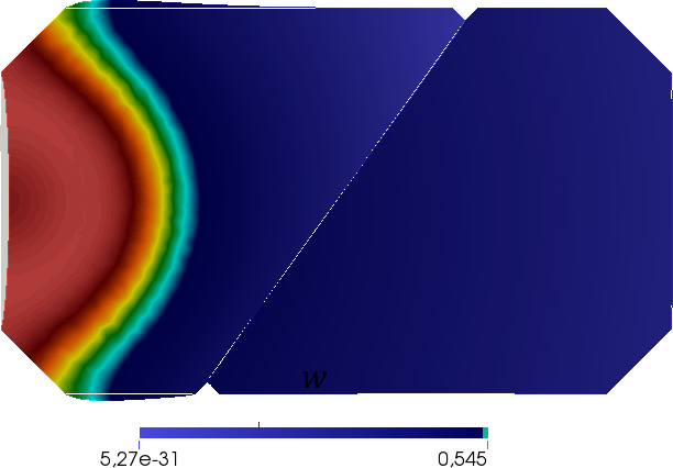
Refer to caption
Refer to caption
Refer to caption
Refer to caption
Refer to caption
Refer to caption
Refer to caption
Refer to caption
Refer to caption
(a) c=0.01𝑐0.01c=0.01
Refer to caption
(b) c=0.5𝑐0.5c=0.5
Figure 15: AR1 geometry and mesh. Time evolution of deformed domain and of the Calcium concentration wave w𝑤w for c={0.01,0.5}𝑐0.010.5c=\{0.01,0.5\}.
Refer to caption
Refer to caption
Refer to caption
Refer to caption
Refer to caption
Refer to caption
Refer to caption
Refer to caption
Refer to caption
(a) c=0.01𝑐0.01c=0.01
Refer to caption
(b) c=0.5𝑐0.5c=0.5
Figure 16: AR2 geometry and mesh. Time evolution of deformed domain and of the Calcium concentration wave w𝑤w for c={0.01,0.5}𝑐0.010.5c=\{0.01,0.5\}.
Refer to caption
Refer to caption
Refer to caption
Refer to caption
Refer to caption
Refer to caption
Refer to caption
Refer to caption
Refer to caption
(a) c=0.01𝑐0.01c=0.01
Refer to caption
(b) c=0.5𝑐0.5c=0.5
Figure 17: AR3 geometry and mesh. Time evolution of deformed domain and of the Calcium concentration wave w𝑤w for c={0.01,0.5}𝑐0.010.5c=\{0.01,0.5\}.

Appendix A Finite element discretization and staggered solution scheme

The staggered solution scheme for the solution of the coupled electromechanical problem for a single myocyete is derived. The displacement vector 𝒖𝒖{\boldsymbol{u}} is approximated in the finite element vector space 𝑽h=[2(Ω0)]2subscript𝑽superscriptdelimited-[]superscript2subscriptΩ02{\boldsymbol{V}}_{h}=[\mathbb{P}^{2}(\Omega_{0})]^{2} of continuous piecewise quadratic triangular Lagrange finite elements, the pressure p𝑝p is approximated in the space Qh=1(Ω0)subscript𝑄superscript1subscriptΩ0Q_{h}=\mathbb{P}^{1}(\Omega_{0}) of linear triangular finite elements, while the electric potential V𝑉V and the Calcium concentration w𝑤w are approximated in the spaces of 𝒱h=𝒲h=2(Ω0)subscript𝒱subscript𝒲superscript2subscriptΩ0\mathcal{V}_{h}=\mathcal{W}_{h}=\mathbb{P}^{2}(\Omega_{0}) of quadratic triangular finite elements. The time interval is partitioned into t0=0tntN=Tfinsuperscript𝑡00superscript𝑡𝑛superscript𝑡𝑁subscript𝑇fint^{0}=0\dots\leq t^{n}\leq\dots t^{N}=T_{\rm fin} and tn+1=tn+Δtsuperscript𝑡𝑛1superscript𝑡𝑛Δ𝑡t^{n+1}=t^{n}+\Delta t where ΔtΔ𝑡\Delta t is the timestep. At each time step tn+1superscript𝑡𝑛1t^{n+1} the mechanical problem (11a) is solved first, where 𝐅ansubscriptsuperscript𝐅𝑛𝑎\mathbf{F}^{n}_{a} and Jansubscriptsuperscript𝐽𝑛𝑎J^{n}_{a} are evaluated at the previous values γlnsubscriptsuperscript𝛾𝑛𝑙\gamma^{n}_{l}, γtnsubscriptsuperscript𝛾𝑛𝑡\gamma^{n}_{t}, such that the following problem is solved for all test functions 𝒗,q𝒗𝑞{\boldsymbol{v}},q:

Ω0μJan𝐅n+1(𝐅an)1(𝐅an)T:𝒗d𝑿Ω0Jn+1pn+1(𝐅n+1)T:𝒗d𝑿=0,𝒗𝑽0,h,:subscriptsubscriptΩ0𝜇subscriptsuperscript𝐽𝑛𝑎superscript𝐅𝑛1superscriptsubscriptsuperscript𝐅𝑛𝑎1superscriptsubscriptsuperscript𝐅𝑛𝑎T𝒗d𝑿subscriptsubscriptΩ0superscript𝐽𝑛1superscript𝑝𝑛1superscriptsuperscript𝐅𝑛1T:formulae-sequence𝒗d𝑿0for-all𝒗subscript𝑽0\displaystyle\int_{\Omega_{0}}\mu J^{n}_{a}\mathbf{F}^{n+1}(\mathbf{F}^{n}_{a})^{-1}(\mathbf{F}^{n}_{a})^{-\rm T}:\nabla{\boldsymbol{v}}\;{\rm d}{\boldsymbol{X}}-\int_{\Omega_{0}}J^{n+1}p^{n+1}(\mathbf{F}^{n+1})^{-\rm T}:\nabla{\boldsymbol{v}}\;{\rm d}{\boldsymbol{X}}=0,\quad\forall{\boldsymbol{v}}\in{\boldsymbol{V}}_{0,h}, (30)
Ω0(Jn+11)qd𝑿=0,qQ0,h,formulae-sequencesubscriptsubscriptΩ0superscript𝐽𝑛11𝑞differential-d𝑿0for-all𝑞subscript𝑄0\displaystyle\int_{\Omega_{0}}(J^{n+1}-1)q\;{\rm d}{\boldsymbol{X}}=0,\quad\forall q\in Q_{0,h},

where the superscript ()n+1superscript𝑛1{(\cdot)}^{n+1} stands for the evaluation on the current field variable. The test fields are defined on spaces of functions vanishing on the Dirichlet part of the domain. Once the value of the current displacement 𝒖n+1superscript𝒖𝑛1{\boldsymbol{u}}^{n+1} is obtained from the solution of (30), the Jacobian Jn+1superscript𝐽𝑛1J^{n+1} and the deformation gradient 𝐅n+1superscript𝐅𝑛1\mathbf{F}^{n+1} are computed, and the nonlinear reaction-diffusion system is solved to find Vn+1,wn+1superscript𝑉𝑛1superscript𝑤𝑛1V^{n+1},w^{n+1}:

1ΔtΩ0(Vn+1Vn)ξd𝑿+Ω01Jn+1(𝐅n+1)1𝐃(𝐅n+1)TVn+1ξd𝑿Ω0In+1ξd𝑿1Δ𝑡subscriptsubscriptΩ0superscript𝑉𝑛1superscript𝑉𝑛𝜉differential-d𝑿subscriptsubscriptΩ01superscript𝐽𝑛1superscriptsuperscript𝐅𝑛11𝐃superscriptsuperscript𝐅𝑛1Tsuperscript𝑉𝑛1𝜉d𝑿limit-fromsubscriptsubscriptΩ0superscript𝐼𝑛1𝜉differential-d𝑿\displaystyle\dfrac{1}{\Delta t}\int_{\Omega_{0}}(V^{n+1}-V^{n})\xi\;{\rm d}{\boldsymbol{X}}+\int_{\Omega_{0}}\dfrac{1}{J^{n+1}}(\mathbf{F}^{n+1})^{-1}\mathbf{D}(\mathbf{F}^{n+1})^{-\rm T}\nabla V^{n+1}\cdot\nabla\xi\;{\rm d}{\boldsymbol{X}}-\int_{\Omega_{0}}I^{n+1}\xi\;{\rm d}{\boldsymbol{X}}- (31)
Ω0Iappξd𝑿=0,ξ𝒱0,h,formulae-sequencesubscriptsubscriptΩ0subscript𝐼app𝜉differential-d𝑿0for-all𝜉subscript𝒱0\displaystyle\int_{\Omega_{0}}I_{\rm app}\xi\;{\rm d}{\boldsymbol{X}}=0,\quad\forall\xi\in\mathcal{V}_{0,h},
1ΔtΩ0(wn+1wn)ϕd𝑿Ω0Hn+1ϕd𝑿=0,ϕ𝒲0,h,formulae-sequence1Δ𝑡subscriptsubscriptΩ0superscript𝑤𝑛1superscript𝑤𝑛italic-ϕdifferential-d𝑿subscriptsubscriptΩ0superscript𝐻𝑛1italic-ϕdifferential-d𝑿0for-allitalic-ϕsubscript𝒲0\displaystyle\dfrac{1}{\Delta t}\int_{\Omega_{0}}(w^{n+1}-w^{n})\phi\;{\rm d}{\boldsymbol{X}}-\int_{\Omega_{0}}H^{n+1}\phi\;{\rm d}{\boldsymbol{X}}=0,\quad\forall\phi\in\mathcal{W}_{0,h},

where the functions In+1superscript𝐼𝑛1I^{n+1} and Hn+1superscript𝐻𝑛1H^{n+1} are given by In+1=In+1(Vn+1,wn+1)superscript𝐼𝑛1superscript𝐼𝑛1superscript𝑉𝑛1superscript𝑤𝑛1I^{n+1}=I^{n+1}(V^{n+1},w^{n+1}) and Hn+1=Hn+1(Vn+1,wn+1)superscript𝐻𝑛1superscript𝐻𝑛1superscript𝑉𝑛1superscript𝑤𝑛1H^{n+1}=H^{n+1}(V^{n+1},w^{n+1}) and the new values of γln+1,γtn+1subscriptsuperscript𝛾𝑛1𝑙subscriptsuperscript𝛾𝑛1𝑡\gamma^{n+1}_{l},\gamma^{n+1}_{t} are computed using Eq. (8) and (3), respectively. Both problems (30) and (31) are nonlinear problems and at each timestep tn+1superscript𝑡𝑛1t^{n+1}, a nested Newton-Raphson iterative scheme must be applied to their linearized counterparts to find approxmate solution of the field variables. Equation (30) must be linearized in order to apply the Newton’s method. The Fréchet devivatives of each term of Eq. (30) are computed as follows. From the first line of Eq. (30):

<d(Ω0μJa𝐅(𝐅a)1(𝐅a)T:𝒗d𝑿)𝒖,δ𝒖>=Ω0μJad𝐅(𝐅a)1(𝐅a)T:𝒗d𝑿,\displaystyle<d(\int_{\Omega_{0}}\mu J_{a}\mathbf{F}(\mathbf{F}_{a})^{-1}(\mathbf{F}_{a})^{-\rm T}:\nabla{\boldsymbol{v}}\;{\rm d}{\boldsymbol{X}})_{{\boldsymbol{u}}},\delta{\boldsymbol{u}}>=\int_{\Omega_{0}}\mu J_{a}d\mathbf{F}(\mathbf{F}_{a})^{-1}(\mathbf{F}_{a})^{-\rm T}:\nabla{\boldsymbol{v}}\;{\rm d}{\boldsymbol{X}},

where d𝐅(𝒖):=(d𝒖)assign𝑑𝐅𝒖𝑑𝒖d\mathbf{F}({\boldsymbol{u}}):=\nabla(d{\boldsymbol{u}}). Recalling that if A𝐴A is a 2×2222\times 2 invertible matrix A=(wxyz)𝐴𝑤𝑥𝑦𝑧A=\left(\begin{array}[]{cc}w&x\\ y&z\end{array}\right), the cofactor matrix is defined as Cof(A)=(zyxw)Cof𝐴𝑧𝑦𝑥𝑤\text{Cof}(A)=\left(\begin{array}[]{cc}z&-y\\ -x&w\end{array}\right) so in 2D2𝐷2D the identity A1=1det(A)Cof(A)Tsuperscript𝐴11𝐴Cofsuperscript𝐴TA^{-1}=\dfrac{1}{\det(A)}\text{Cof}(A)^{\rm T} holds. Then:

<d(Ω0Jp𝐅T:𝐯d𝑿)𝒖,δ𝒖>=Ω0pCof(d𝐅):𝐯d𝑿,<d(\int_{\Omega_{0}}Jp\mathbf{F}^{-T}:\nabla\mathbf{v}\;{\rm d}{\boldsymbol{X}})_{{\boldsymbol{u}}},\delta{\boldsymbol{u}}>=\int_{\Omega_{0}}p\text{Cof}(d\mathbf{F}):\nabla\mathbf{v}\;{\rm d}{\boldsymbol{X}},

where the realtions J𝐅T=Cof(𝐅)𝐽superscript𝐅TCof𝐅J\mathbf{F}^{-\rm T}=\text{Cof}(\mathbf{F}) and dCof(𝐅)=Cof(d𝐅)𝑑Cof𝐅Cof𝑑𝐅d\text{Cof}(\mathbf{F})=\text{Cof}(d\mathbf{F}) were used. Then is computed:

<d(Ω0Jp𝐅T:𝒗d𝑿)p,δp>=Ω0Jdp𝐅T:𝒗d𝑿.<d(\int_{\Omega_{0}}Jp\mathbf{F}^{-\rm T}:\nabla{\boldsymbol{v}}\;{\rm d}{\boldsymbol{X}})_{p},\delta p>=\\ \int_{\Omega_{0}}Jdp\mathbf{F}^{-T}:\nabla{\boldsymbol{v}}\;{\rm d}{\boldsymbol{X}}.

Finally, from the identity J𝒖=J𝐅T:𝐅𝒖:𝐽𝒖𝐽superscript𝐅T𝐅𝒖\dfrac{\partial J}{\partial{\boldsymbol{u}}}=J\mathbf{F}^{-\rm T}:\dfrac{\partial\mathbf{F}}{\partial{\boldsymbol{u}}} it follows:

<d(Ω0(J1)qd𝑿)𝒖,δ𝒖>=Ω0J𝐅T:d𝐅qd𝑿.:formulae-sequenceabsent𝑑subscriptsubscriptsubscriptΩ0𝐽1𝑞differential-d𝑿𝒖𝛿𝒖subscriptsubscriptΩ0𝐽superscript𝐅T𝑑𝐅𝑞d𝑿<d(\int_{\Omega_{0}}(J-1)q\;{\rm d}{\boldsymbol{X}})_{{\boldsymbol{u}}},\delta{\boldsymbol{u}}>=\int_{\Omega_{0}}J\mathbf{F}^{-\rm T}:d\mathbf{F}q\;{\rm d}{\boldsymbol{X}}.

Dropping the superscript denoting time discretization, the linearized equation (30) to be solved in the correction (δ𝒖,δp)𝛿𝒖𝛿𝑝(\delta{\boldsymbol{u}},\delta p) at each Newton-Raphson iteration is: Given values at previous time iteration (𝒖n,pn)superscript𝒖𝑛superscript𝑝𝑛({\boldsymbol{u}}^{n},p^{n}) and values at previous Newton-Raphson iteration (𝒖kn+1,pkn+1)subscriptsuperscript𝒖𝑛1𝑘subscriptsuperscript𝑝𝑛1𝑘({\boldsymbol{u}}^{n+1}_{k},p^{n+1}_{k}) of displacement field and pressure, find the corrections (δ𝒖,δp)𝛿𝒖𝛿𝑝(\delta{\boldsymbol{u}},\delta p) such that:

Ω0μJanδ𝐅(𝐅an)1(𝐅an)T:𝒗d𝑿Ω0pkn+1Cof(δ𝐅):𝒗d𝑿Ω0Jkn+1δp(𝐅kn+1)T:𝒗d𝑿+:subscriptsubscriptΩ0𝜇subscriptsuperscript𝐽𝑛𝑎𝛿𝐅superscriptsubscriptsuperscript𝐅𝑛𝑎1superscriptsubscriptsuperscript𝐅𝑛𝑎T𝒗d𝑿subscriptsubscriptΩ0subscriptsuperscript𝑝𝑛1𝑘Cof𝛿𝐅:𝒗d𝑿subscriptsubscriptΩ0subscriptsuperscript𝐽𝑛1𝑘𝛿𝑝superscriptsubscriptsuperscript𝐅𝑛1𝑘T:limit-from𝒗d𝑿\displaystyle\int_{\Omega_{0}}\mu J^{n}_{a}\delta\mathbf{F}(\mathbf{F}^{n}_{a})^{-1}(\mathbf{F}^{n}_{a})^{-\rm T}:\nabla{\boldsymbol{v}}\;{\rm d}{\boldsymbol{X}}-\int_{\Omega_{0}}p^{n+1}_{k}\text{Cof}(\delta\mathbf{F}):\nabla{\boldsymbol{v}}\;{\rm d}{\boldsymbol{X}}-\int_{\Omega_{0}}J^{n+1}_{k}\delta p(\mathbf{F}^{n+1}_{k})^{-\rm T}:\nabla{\boldsymbol{v}}\;{\rm d}{\boldsymbol{X}}+
Ω0Jkn+1(𝐅kn+1)T:δ𝐅qd𝑿=R(𝒖kn+1,pkn+1),𝒗𝑽0,h,qQ0,h,:subscriptsubscriptΩ0subscriptsuperscript𝐽𝑛1𝑘superscriptsubscriptsuperscript𝐅𝑛1𝑘Tformulae-sequence𝛿𝐅𝑞d𝑿𝑅subscriptsuperscript𝒖𝑛1𝑘subscriptsuperscript𝑝𝑛1𝑘formulae-sequencefor-all𝒗subscript𝑽0𝑞subscript𝑄0\displaystyle\int_{\Omega_{0}}J^{n+1}_{k}(\mathbf{F}^{n+1}_{k})^{-\rm T}:\delta\mathbf{F}q\;{\rm d}{\boldsymbol{X}}=-R({\boldsymbol{u}}^{n+1}_{k},p^{n+1}_{k}),\qquad\forall{\boldsymbol{v}}\in{\boldsymbol{V}}_{0,h},q\in Q_{0,h},

where δ𝐅=(δ𝒖)𝛿𝐅𝛿𝒖\delta\mathbf{F}=\nabla(\delta{\boldsymbol{u}}) and R(𝒖kn+1,pkn+1)𝑅subscriptsuperscript𝒖𝑛1𝑘subscriptsuperscript𝑝𝑛1𝑘R({\boldsymbol{u}}^{n+1}_{k},p^{n+1}_{k}) is the residual given by:

R(𝒖kn+1,pkn+1)=𝑅subscriptsuperscript𝒖𝑛1𝑘subscriptsuperscript𝑝𝑛1𝑘absent\displaystyle R({\boldsymbol{u}}^{n+1}_{k},p^{n+1}_{k})= Ω0μJan𝐅kn+1(𝐅an)1(𝐅an)T:𝒗d𝑿Ω0Jkn+1pkn+1(𝐅kn+1)T:𝒗d𝑿+Ω0(Jkn+11)qd𝑿:subscriptsubscriptΩ0𝜇subscriptsuperscript𝐽𝑛𝑎subscriptsuperscript𝐅𝑛1𝑘superscriptsubscriptsuperscript𝐅𝑛𝑎1superscriptsubscriptsuperscript𝐅𝑛𝑎T𝒗d𝑿subscriptsubscriptΩ0subscriptsuperscript𝐽𝑛1𝑘subscriptsuperscript𝑝𝑛1𝑘superscriptsubscriptsuperscript𝐅𝑛1𝑘T:𝒗d𝑿subscriptsubscriptΩ0subscriptsuperscript𝐽𝑛1𝑘1𝑞differential-d𝑿\displaystyle\int_{\Omega_{0}}\mu J^{n}_{a}\mathbf{F}^{n+1}_{k}(\mathbf{F}^{n}_{a})^{-1}(\mathbf{F}^{n}_{a})^{-\rm T}:\nabla{\boldsymbol{v}}\;{\rm d}{\boldsymbol{X}}-\int_{\Omega_{0}}J^{n+1}_{k}p^{n+1}_{k}(\mathbf{F}^{n+1}_{k})^{-\rm T}:\nabla{\boldsymbol{v}}\;{\rm d}{\boldsymbol{X}}+\int_{\Omega_{0}}(J^{n+1}_{k}-1)q\;{\rm d}{\boldsymbol{X}}

The stopping criterion is:

δ𝒖𝐇1(Ω0)2𝒖kn+1𝐇1(Ω0)2+δpL2(Ω0)2pkn+1L2(Ω0)2<tolm,subscriptsuperscriptnorm𝛿𝒖2superscript𝐇1subscriptΩ0subscriptsuperscriptnormsubscriptsuperscript𝒖𝑛1𝑘2superscript𝐇1subscriptΩ0subscriptsuperscriptnorm𝛿𝑝2superscript𝐿2subscriptΩ0subscriptsuperscriptnormsubscriptsuperscript𝑝𝑛1𝑘2superscript𝐿2subscriptΩ0subscripttolm\dfrac{\|\delta{\boldsymbol{u}}\|^{2}_{\mathbf{H}^{1}(\Omega_{0})}}{\|{\boldsymbol{u}}^{n+1}_{k}\|^{2}_{\mathbf{H}^{1}(\Omega_{0})}}+\dfrac{\|\delta p\|^{2}_{L^{2}(\Omega_{0})}}{\|p^{n+1}_{k}\|^{2}_{L^{2}(\Omega_{0})}}<\rm{tol_{m}},

where tolmsubscripttolm{\rm tol_{m}} is a given tolerance and the norm 𝐇1(Ω0)2\|\cdot\|^{2}_{\mathbf{H}^{1}(\Omega_{0})} is defined as 𝒖𝐇1(Ω0)2=𝒖𝐋2(Ω0)2+𝒖𝐋2(Ω0)2subscriptsuperscriptnorm𝒖2superscript𝐇1subscriptΩ0subscriptsuperscriptnorm𝒖2superscript𝐋2subscriptΩ0subscriptsuperscriptnorm𝒖2superscript𝐋2subscriptΩ0\|{\boldsymbol{u}}\|^{2}_{\mathbf{H}^{1}(\Omega_{0})}=\|{\boldsymbol{u}}\|^{2}_{\mathbf{L}^{2}(\Omega_{0})}+\|\nabla{\boldsymbol{u}}\|^{2}_{\mathbf{L}^{2}(\Omega_{0})}, while the norm 𝐋2(Ω0)2\|\cdot\|^{2}_{\mathbf{L}^{2}(\Omega_{0})} is the usual integral squared (vector) norm.

At timestep tn+1superscript𝑡𝑛1t^{n+1}, after convergence of the mechanical problem, the new values of displacement and pressure 𝒖n+1superscript𝒖𝑛1{\boldsymbol{u}}^{n+1} and pn+1superscript𝑝𝑛1p^{n+1} are used to compute Jn+1superscript𝐽𝑛1J^{n+1} and 𝐅n+1superscript𝐅𝑛1{\mathbf{F}}^{n+1} entering the reaction-diffusion system (31). The reaction-diffusion system (31) is a nonlinear system in the reaction electrophysiological functions I(V,w),H(V,w)𝐼𝑉𝑤𝐻𝑉𝑤I(V,w),H(V,w). A nested Newton-Raphson scheme must be used to find an approximate solution Vn+1,wn+1superscript𝑉𝑛1superscript𝑤𝑛1V^{n+1},w^{n+1} of the linearized counterpart of (31). At the k𝑘k-th Newton-Raphson iteration, given the values of the electrophysiological variables Vn,wnsuperscript𝑉𝑛superscript𝑤𝑛V^{n},w^{n} and Vn+1,k,wn+1,ksuperscript𝑉𝑛1𝑘superscript𝑤𝑛1𝑘V^{n+1,k},w^{n+1,k} respectively at the previous timestep and Netwon-Raphson iteration, it must be solved the following reaction-diffusion system in the corrections δV,δw𝛿𝑉𝛿𝑤\delta V,\delta w for all test functions ξ,ϕ𝜉italic-ϕ\xi,\phi vanishing on the corresponding Dirichlet part of the domain:

1ΔtΩ0δVξd𝑿+Ω01Jn+1(𝐅n+1)1𝐃(𝐅n+1)TδVξd𝑿Ω0Ikn+1VδVξd𝑿Ω0Ikn+1wδwξd𝑿1Δ𝑡subscriptsubscriptΩ0𝛿𝑉𝜉differential-d𝑿subscriptsubscriptΩ01superscript𝐽𝑛1superscriptsuperscript𝐅𝑛11𝐃superscriptsuperscript𝐅𝑛1T𝛿𝑉𝜉d𝑿subscriptsubscriptΩ0subscriptsuperscript𝐼𝑛1𝑘𝑉𝛿𝑉𝜉differential-d𝑿subscriptsubscriptΩ0subscriptsuperscript𝐼𝑛1𝑘𝑤𝛿𝑤𝜉differential-d𝑿\displaystyle\dfrac{1}{\Delta t}\int_{\Omega_{0}}\delta V\xi\;{\rm d}{\boldsymbol{X}}+\int_{\Omega_{0}}\dfrac{1}{J^{n+1}}(\mathbf{F}^{n+1})^{-1}\mathbf{D}(\mathbf{F}^{n+1})^{-\rm T}\nabla\delta V\cdot\nabla\xi\;{\rm d}{\boldsymbol{X}}-\int_{\Omega_{0}}\dfrac{\partial I^{n+1}_{k}}{\partial V}\delta V\xi\;{\rm d}{\boldsymbol{X}}-\int_{\Omega_{0}}\dfrac{\partial I^{n+1}_{k}}{\partial w}\delta w\xi\;{\rm d}{\boldsymbol{X}}
=RV(vkn+1,wkn+1),ξ𝒱0,h,formulae-sequenceabsentsubscript𝑅𝑉subscriptsuperscript𝑣𝑛1𝑘subscriptsuperscript𝑤𝑛1𝑘for-all𝜉subscript𝒱0\displaystyle=-R_{V}(v^{n+1}_{k},w^{n+1}_{k}),\quad\forall\xi\in\mathcal{V}_{0,h},
1ΔtΩ0δwϕd𝑿Ω0Hkn+1VδVϕd𝑿Ω0Hkn+1wδwϕd𝑿=Rw(Vkn+1,wkn+1),ϕ𝒲0,h,formulae-sequence1Δ𝑡subscriptsubscriptΩ0𝛿𝑤italic-ϕdifferential-d𝑿subscriptsubscriptΩ0subscriptsuperscript𝐻𝑛1𝑘𝑉𝛿𝑉italic-ϕdifferential-d𝑿subscriptsubscriptΩ0subscriptsuperscript𝐻𝑛1𝑘𝑤𝛿𝑤italic-ϕdifferential-d𝑿subscript𝑅𝑤subscriptsuperscript𝑉𝑛1𝑘subscriptsuperscript𝑤𝑛1𝑘for-allitalic-ϕsubscript𝒲0\displaystyle\dfrac{1}{\Delta t}\int_{\Omega_{0}}\delta w\phi\;{\rm d}{\boldsymbol{X}}-\int_{\Omega_{0}}\dfrac{\partial H^{n+1}_{k}}{\partial V}\delta V\phi\;{\rm d}{\boldsymbol{X}}-\int_{\Omega_{0}}\dfrac{\partial H^{n+1}_{k}}{\partial w}\delta w\phi\;{\rm d}{\boldsymbol{X}}=-R_{w}(V^{n+1}_{k},w^{n+1}_{k}),\quad\forall\phi\in\mathcal{W}_{0,h},

where the residuals for the two equations are:

Rv(Vkn+1,wkn+1)=subscript𝑅𝑣subscriptsuperscript𝑉𝑛1𝑘subscriptsuperscript𝑤𝑛1𝑘absent\displaystyle R_{v}(V^{n+1}_{k},w^{n+1}_{k})= 1ΔtΩ0(Vn+1,kVn)ξd𝑿+Ω01Jn+1(𝐅n+1)1𝐃(𝐅n+1)TVn+1,kξd𝑿1Δ𝑡subscriptsubscriptΩ0superscript𝑉𝑛1𝑘superscript𝑉𝑛𝜉differential-d𝑿limit-fromsubscriptsubscriptΩ01superscript𝐽𝑛1superscriptsuperscript𝐅𝑛11𝐃superscriptsuperscript𝐅𝑛1Tsuperscript𝑉𝑛1𝑘𝜉d𝑿\displaystyle\dfrac{1}{\Delta t}\int_{\Omega_{0}}(V^{n+1,k}-V^{n})\xi\;{\rm d}{\boldsymbol{X}}+\int_{\Omega_{0}}\dfrac{1}{J^{n+1}}(\mathbf{F}^{n+1})^{-1}\mathbf{D}(\mathbf{F}^{n+1})^{-\rm T}\nabla V^{n+1,k}\cdot\nabla\xi\;{\rm d}{\boldsymbol{X}}-
Ω0Ikn+1Vn+1,kξd𝑿Ω0Iappξd𝑿,subscriptsubscriptΩ0subscriptsuperscript𝐼𝑛1𝑘superscript𝑉𝑛1𝑘𝜉differential-d𝑿subscriptsubscriptΩ0subscript𝐼app𝜉differential-d𝑿\displaystyle\int_{\Omega_{0}}I^{n+1}_{k}V^{n+1,k}\xi\;{\rm d}{\boldsymbol{X}}-\int_{\Omega_{0}}I_{\rm app}\xi\;{\rm d}{\boldsymbol{X}},

and

Rw(Vkn+1,wkn+1)=1ΔtΩ0(wn+1,kwn)ϕd𝑿Ω0Hkn+1ϕd𝑿.subscript𝑅𝑤subscriptsuperscript𝑉𝑛1𝑘subscriptsuperscript𝑤𝑛1𝑘1Δ𝑡subscriptsubscriptΩ0superscript𝑤𝑛1𝑘superscript𝑤𝑛italic-ϕdifferential-d𝑿subscriptsubscriptΩ0subscriptsuperscript𝐻𝑛1𝑘italic-ϕdifferential-d𝑿R_{w}(V^{n+1}_{k},w^{n+1}_{k})=\dfrac{1}{\Delta t}\int_{\Omega_{0}}(w^{n+1,k}-w^{n})\phi\;{\rm d}{\boldsymbol{X}}-\int_{\Omega_{0}}H^{n+1}_{k}\phi\;{\rm d}{\boldsymbol{X}}. (32)

The stopping criterion is δVL2(Ω0)2+δwL2(Ω0)2<tolesubscriptsuperscriptnorm𝛿𝑉2superscript𝐿2subscriptΩ0subscriptsuperscriptnorm𝛿𝑤2superscript𝐿2subscriptΩ0subscripttole\|\delta V\|^{2}_{L^{2}(\Omega_{0})}+\|\delta w\|^{2}_{L^{2}(\Omega_{0})}<\rm{tol_{e}}, where tolesubscripttole\rm{tol_{e}} is a given tolerance.