Amending entanglement-breaking channels via intermediate unitary operations
Abstract
We report a bulk optics experiment demonstrating the possibility of restoring the entanglement distribution through noisy quantum channels by inserting a suitable unitary operation (filter) in the middle of the transmission process. We focus on two relevant classes of single-qubit channels consisting in repeated applications of rotated phase damping or rotated amplitude damping maps, both modeling the combined Hamiltonian and dissipative dynamics of the polarization state of single photons. Our results show that interposing a unitary filter between two noisy channels can significantly improve entanglement transmission. This proof-of-principle demonstration could be generalized to many other physical scenarios where entanglement-breaking communication lines may be amended by unitary filters.
I Introduction
Real quantum communication channels are typically not perfect transmission lines, since they usually introduce different kinds of noises given by the intrinsic mechanisms that transfer information or by external perturbations. Physically, such channels disturb the transmitted messages by gradually degrading the information along their structures barnum ; schumacher ; nielsen97 , and this effect may be particularly severe when entangled qubits are propagated through them. The extreme limit is represented by entanglement-breaking (EB) channels horodecki2003 which are so noisy to be useless for entanglement distribution even exploiting distillation techniques bennet1996 , with direct consequences on the associated classical or quantum capacities channelcapacity .
In many practical situations, quantum channels can be represented as the consecutive application of a given elementary map repeated times, where is a positive integer. In this cases, the full channel is given by
| (1) |
and the integer can be interpreted as the effective length of the transmission line. For example if the elementary map corresponds to the spatial propagation of a quantum state along a physical medium of length , then the total length of the channel is . Alternatively if models the dissipative evolution of the system lasting an elementary time interval , then represents the total time duration of the whole process. In these cases one may ask what is the maximum entanglement propagation length or, equivalently, what is the minimum such that is EB. Such a number can be seen as a sort of noise quantifier for the elementary map and corresponds to its entanglement-breaking order originally defined in depasquale2012 , and further investigated in depasquale2013 ; lami2015 ; cutandpaste .
In this work we give an experimental proof-of-principle demonstration that the propagation length can be increased by placing an intermediate unitary operation (filter) between the two elementary maps . More precisely, we implement two different examples (built up exploiting single-qubit phase-damping and amplitude-damping channels respectively) of an elementary map such that:
| (2) | |||
| (3) |
for a suitable unitary operation . In practice, the action of the filter is to “amend” the otherwise EB communication line, by properly acting in the middle of the transmission process. Therefore the length of the channel up to which quantum correlations are preserved is increased. This idea has been theoretically introduced in depasquale2012 . Together with the recent results reported in Ref. cutandpaste in which dissipative correcting operations have been considered, the present work represents the first experimental demonstration of such an entanglement recovery technique.
The manuscript is organized as follows. In Section I, we present the idea and the theoretical model of the two experiments: the first one based on rotated phase damping maps and the second one based on rotated amplitude damping maps. In Section II we present all the details of the experimental implementation. In Section III we report and discuss the experimental results. Eventually, in Section V we draw some conclusions.
II Theoretical model of the experiment
In this section we present the two experimental schemes that we used to verify the unitary filtering phenomenon compactly summarized by Eq.s (2) and (3). For both experiments we focused on single-qubit channels acting on the polarization state of individual photons. The vertical and horizontal polarizations of the photon form a basis of a two-dimensional Hilbert space. In this basis, a generic quantum state can be expressed as a density matrix , such that and .
As real candidates for the elementary map appearing in Eq.s (2), we considered the rotated phase damping and the rotated amplitude damping maps, respectively given by the following composition of operations:
| (4) | |||
| (5) |
where and are unitary rotations defined by:
| (6) |
is the phase-damping channel nielsen-chuang ; desurvire with damping parameter :
| (7) |
while is the amplitude damping channel nielsen-chuang ; desurvire with parameter :
| (8) |
with and . In both cases ( and ), as a potential candidate for the generic unitary filter appearing in (3), we use
| (9) |
where is an angle that we are going to optimize and is a unitary operation defined analogously to as in Eq. (6). Our aim is to experimentally verify that there exists values/intervals of the damping parameters , and of the filter angle such that both conditions (2) and (3) are fulfilled, demonstrating that the unitary filter succeeds in increasing the entanglement propagation distance.
Before presenting the details of the experimental implementation, we anticipate here how the previous three maps (6) (7) and (8) can be realized using standard bulk optics elements such as beam splitters, phase plates etc., and how one can experimentally test whether a given sequence of maps is entanglement breaking or not. The implementation of the unitary rotation is very simple since it corresponds to the application of a phase plate rotated by an angle around the propagation axis of the photon. The phase-damping channel (7) can also be implemented quite easily as a probabilistic switch between the identity operation and the map . The application of the amplitude-damping channel (8) to a polarization qubit is instead less straightforward but can still be simulated with a suitable interferometric scheme as explained in the next section. Finally we recall that, in order to test whether a channel is entanglement breaking or not, it is sufficient to apply it to a subsystem of a maximally entangled state and check the separability of the output state horodecki2003 :
| (10) |
where is the identity map on an arbitrary ancillary system , and is a maximally entangled state of the bipartite system composed by the considered system and .
III Experimental Implementation
Our experimental scheme adopts a Sagnac interferometric source of polarization-entangled photons source in a Bell state , () being the horizontal (vertical) polarization. The photons are generated in two indistinguishable Type-II parametric down-conversion processes inside a PPKTP nonlinear crystal. Here, the photons belonging to a continuous wave laser of are converted into twin photons of at a rate and heralded efficiency revealed by two synchronized avalanche photo-detectors (APDs). The high purity of the generated state was measured, giving a fidelity of to entanglement and a concurrence of concurrence . In order to take into account the non perfect purity of the input entangled state, we can model it as a Werner state wernerstate ; channelcapacity , where is the identity operator associated to subsystem .
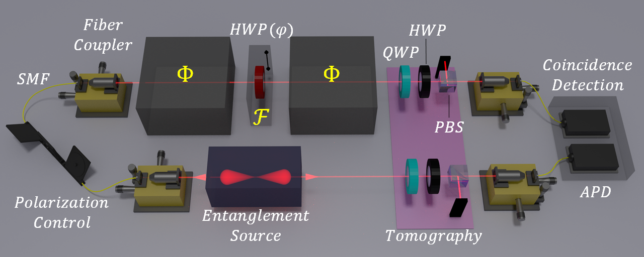
In order to test condition (10) in the laboratory, the -photon (i.e. the photon which embodies the system ) is injected in a bulk optics setup that implements or , while the -photon (i.e. the ancillary system) propagates in free space. The bipartite output state is measured by a hyper-complete tomography setup tomography (see Fig. 1). Then, the - and -photons are coupled into single-mode fibers (SMF) directly connected to an APD. The setup allows to measure the degree of entanglement remaining after the action of each implemented map.
Rotating Phase Damping Channel: To simulate each channel (Eq. (7)), two operations are needed, and . They are simply implemented by the absence or presence of a half-wave plate (HWP) fixed at degrees in the optical path of the photon, respectively. To simulate another HWP is permanently placed after , but with a rotation degree of freedom in the angle (as seen in Fig. 2 a)) channelcapacity ; pauli_channel .
Since both plates are synchronized in their rotation angle, there are only four combinations of Pauli operations; when the first is applying , the second can apply or ; when the first is applying , the second can apply or . Then, the statistical mixture between and is obtained by extracting a fraction of coincidences from the tomography, a fraction of coincidences from the and tomographies, and a fraction from the tomography.
Once the tomography registry fractions are combined, the new registry will be equivalent to a tomography of the state under a the action of .
a) 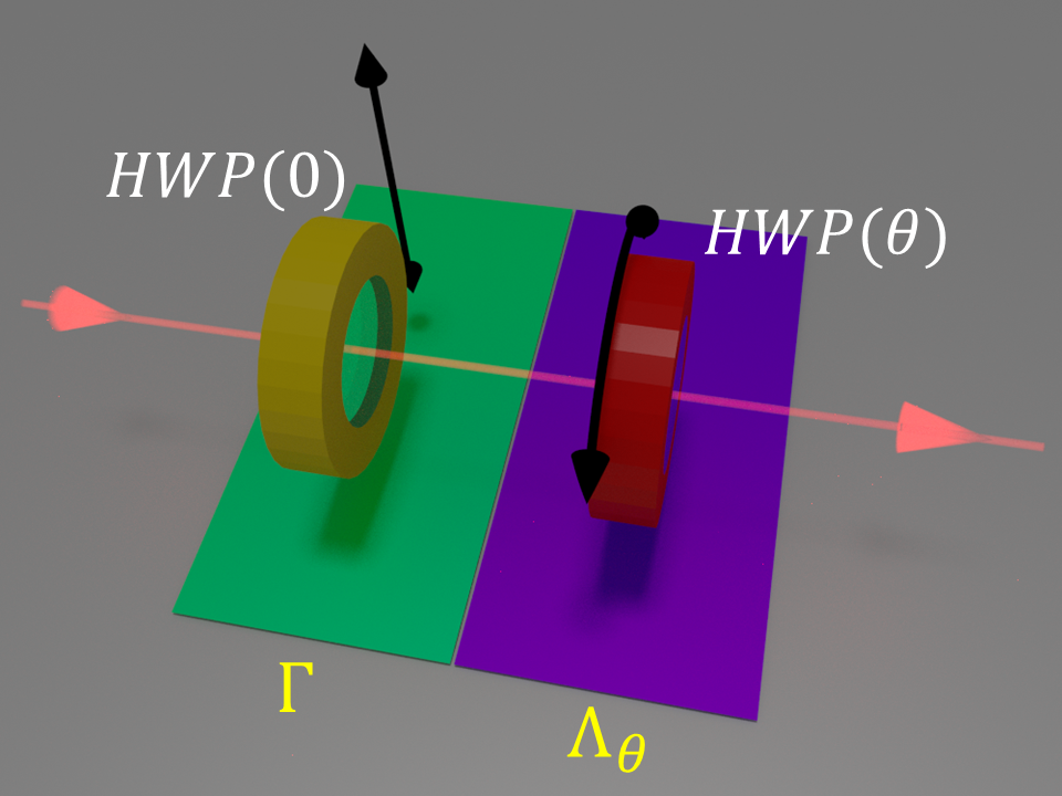 b)
b) 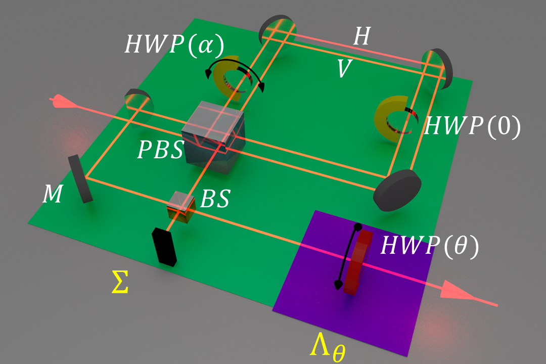
Rotating Amplitude Damping Channel: To simulate each channel, we use a displaced Sagnac interferometer (SI), opened and closed by a single polarizing beam splitter (PBS) (as seen in Fig. 2 b)). The parallel trajectories of and projections inside the SI are temporally compensated and go in clockwise and counter-clockwise directions, respectively. Both trajectories are intercepted by independent HWPs, a rotating one for and another unrotated for . The rotation angle is related to the damping parameter by the expression cutandpaste ; channelcapacity .
After the SI there is an unbalanced Mach-Zehnder interferometer (MZI), that allows to couple in the same trajectory the damped and undamped polarizations as they pass through a beam splitter (BS). The temporal difference between the MZI arms is set to a value larger than the coherence length of the photons in order to simulate random phase fluctuations that destroy quantum interferences at its output.
The action of is then obtained by selecting the same damping in both , while both HWPs corresponding to rotate in a synchronous way.
Filtering: The protocol firstly requires to fix the damping parameter for or for , to scan the channel in the rotation angle and verify the location of periodic EB regions. It results that these regions are located around for the experiment and around for the experiment, in both cases with . Once this condition is experimentally certified, one proceeds to fix the angle or . Then, the operation of is studied by scanning the rotation of an extra HWP (as seen in Fig. 1).
As a consequence, either or will be no more , in a region where, on the contrary, and were EB.
IV Results
In Fig. 3 we report the experimental results for the channels and acting over the -photon of a pair of entangled photons, with the damping parameter set to the value . Fig. 3 a) shows the EB behaviour of around as predicted by the simulated model, while Fig.3 b) shows an entanglement revival of for . Similarly, in Fig. 4 we report the results of and channels acting over the -photon from a pair of entangled photons, having set the damping parameter to the value . Fig. 4 a) shows the behavior of around as predicted by the simulated model, while Fig.4 b) shows an entanglement revival of for .
The experimental data were obtained by averaging and calculating the standard deviation over 5 values per point. The blue lines were calculated considering perfect input state and optical conditions. The simulated shaded green areas correspond to the regions of all possible experimental results within one standard deviation of for and , and also considering the error propagation of 0.5 degrees of uncertainty in for and . This difference in the data analysis between PD and AD channel origins from the negligible error contribution of degrees of uncertainty in channels. All values have error bars within the size of the point.
a) 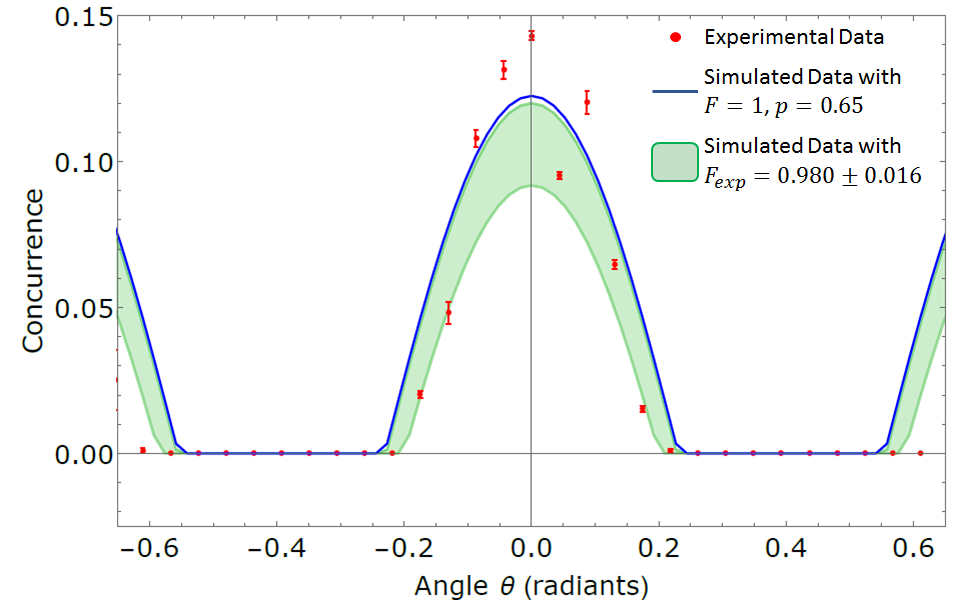
b) 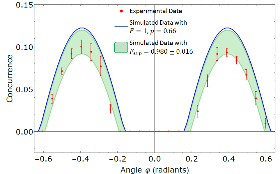
The simulated data considered two scenarios: one with perfect optical elements (POE) and maximally pure entangled input state, and another with realistic optical elements (ROE), non maximally pure entangled input state and error propagation. The differences between these two cases are described in TABLE 1.
| POE | Average ROE | |
|---|---|---|
| Fidelity | 1 | |
| 0.5 | ||
| 0.5 | ||
| 0.5 | ||
| 0.5 | ||
| 1 | ||
| 0 | ||
| 0 | ||
| 1 |
In both (Fig.3) and (Fig.4) cases there is a good agreement between experimental and simulated data. The discrepancies existing between , and their simulations could be attributed to the post-processing generation of the channel, since their action has been simulated by combining and operations with unstable photon counts during long-time scans varying and rotation angles. On the other hand, discrepancies between , and their simulations are strongly related to the difficulty of coupling the 16 possible spatial modes within a unique SMF at the end of the entire channel.
a) 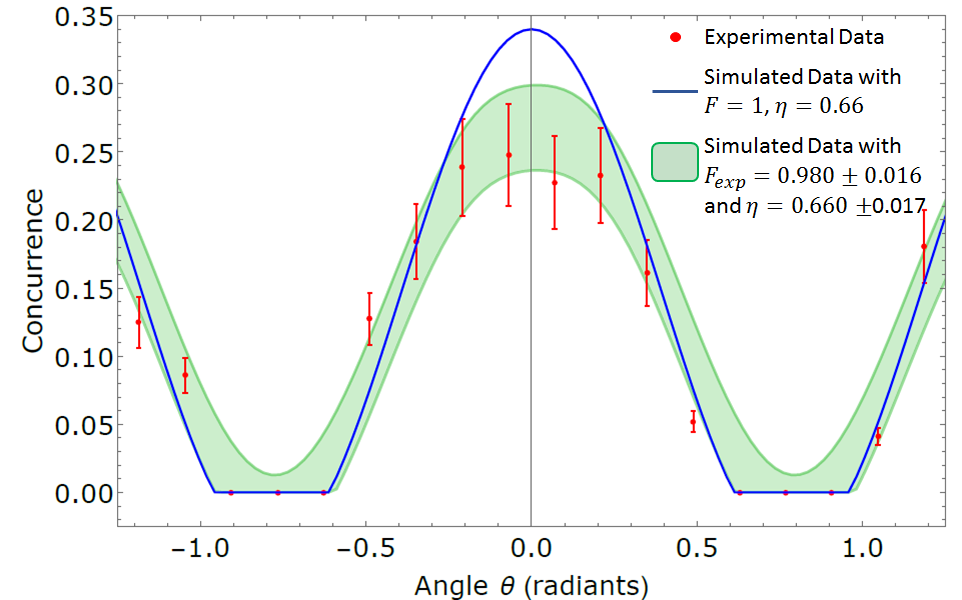
b) 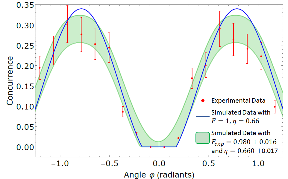
V Conclusions
We have given an experimental proof for a method aiming at increasing the entanglement transmission distance, applicable to communication lines decomposable into elementary maps. The technique consists in placing appropriate unitary operations between the elementary steps of the channel, allowing to restore the entanglement transmissivity of an initially entanglement-breaking communication line.
We implemented different single-qubit channels acting on the polarization of single photons combining standard bulk optics elements: rotated phase plates, beam splitters and photo-detectors. We applied such channels to a subsystem of a maximally entangled state, and computed the remaining fraction of entanglement after performing a two-photon state tomography. We measured clear revivals of the output entanglement whenever a unitary filter, consisting in a phase-plate with appropriate rotation angle, was placed in the middle of the transmission process.
Our results could be extended to more general physical scenarios involving different single qubit operations depasquale2012 , continuous and non-unitary channels cutandpaste , or amendable Gaussian maps depasquale2013 .
VI Acknowledgements
Á. Cuevas would like to thank the support from the Chilean agency CONICYT and to its PhD scholarships program.
J. Ferraz would like to thank the support from the Brazilian agency CAPES and the CsF program.
References
- (1) H. Barnum, M. A. Nielsen, and B. Schumacher, Phys. Rev. A 57, 4153 (1998).
- (2) B. W. Schumacher, Phys. Rev. A 54, 2614 (1996).
- (3) I. L. Chuang and M. A. Nielsen, Journal of Modern Optics 44, 11, 2455 (1997).
- (4) M. Horodecki, P. W. Shor and M. B. Ruskai, Rev. Math. Phys 15, 629 (2003).
- (5) C. H. Bennett, G. Brassard, S. Popescu, B. Schumacher, J. A. Smolin, and W. K. Wootters, Phys. Rev. Lett. 76, 722 (1996).
- (6) Á. Cuevas, M. Proietti, M. A. Ciampini, S. Duranti, P. Mataloni, M. Sacchi, C. Macchiavello. arXiv:1612.07754 (2016).
- (7) A. De Pasquale and V. Giovannetti, Phys. Rev. A 86, 052302 (2012).
- (8) A. De Pasquale, A. Mari, A. Porzio and V. Giovannetti, Phys. Rev. A 87, 062307 (2013).
- (9) L. Lami and V. Giovannetti, J. of Math. Phys. 56, 092201 (2015).
- (10) Á. Cuevas, A. Mari, A. De Pasquale, A. Orieux, M. Massaro, F. Sciarrino, P. Mataloni, V. Giovannetti arXiv:1604.08350 (2016), to appear soon in Phys. Rev. A. (2017).
- (11) R. Horodecki, P. Horodecki, M. Horodecki, and K. Horodecki, Rev. Mod. Phys. 81, 865 (2009).
- (12) M. A. Nielsen and I. L. Chuang. Quantum Computation and Quantum Information (Cambridge University Press, Cambridge, 2010).
- (13) E. Desurvire. Classical and Quantum Information Theory: An Introduction for the Telecom Scientist (Cambridge University Press, Cambridge, 2009).
- (14) N. K. Bernardes, Á. Cuevas, A. Orieux, C. H. Monken, P. Mataloni, F. Sciarrino and M. F. Santos. Scientific Reports 5, 17520 (2015).
- (15) J. Jin, V. Giovannetti, R. Fazio, F. Sciarrino, P. Mataloni, A. Crespi and Roberto Osellame. Phys. Rev. A 91, 012122 (2015).
- (16) A. Fedrizzi, et al., Optics Express 15, 23, 15377 (2007).
- (17) R. Horodecki, P. Horodecki, M. Horodecki, and K. Horodecki, Rev. Mod. Phys. 81, 865 (2009).
- (18) William K. Wootters. Phys. Rev. Lett. 80, 10 (1998).
- (19) M. Barbieri, F. De Martini, G. Di Nepi, and P. Mataloni. Phyx. Rev. Lett. 92,17 (2004).
- (20) D. James, P. Kwiat, W. Munro, and A. White. Phys. Rev. A, 64, 052312 (2001).
- (21) A. Chiuri, V. Rosati, G. Vallone, S. Pádua, H. Imai, S. Giacomini, C. Macchiavello, and P. Mataloni. Phys. Rev. Lett. 107 (2011).