Levitated optomechanics with a fiber Fabry-Perot interferometer
Abstract
In recent years quantum phenomena have been experimentally demonstrated on variety of optomechanical systems ranging from micro-oscillators to photonic crystals. Since single photon couplings are quite small, most experimental approaches rely on the realization of high finesse Fabry-Perot cavities in order to enhance the effective coupling. Here we show that by exploiting a, long path, low finesse fiber Fabry-Perot interferometer ground state cooling can be achieved. We model a m long cavity with a finesse of and analyze the impact of additional noise sources arising from the fiber. As a mechanical oscillator we consider a levitated microdisk but the same approach could be applied to other optomechanical systems.
Cavity optomechanicsakm has achieved several long-awaited experimental results highlighting the quantum nature of the interaction. From the generation of ponderomotive squeezingbrooks ; painter ; purdy and field quadrature QND measurementmy1 to the cooling of the mechanical motion to a thermal occupation number below unityconnel ; teufel ; chan ; harris . These results, obtained in a variety of systems, have increased the interest in the generation of other non-classical states and in the investigation of the quantum to classical transition. In recent years, optical cooling of levitated dielectric nanoparticlesnanop has been receiving a lot of attention. These unclamped oscillators offer the possibility to be operated in a regime where thermal noise, due to the residual background gas, is not the main contribution to the overall decoherence rate. Typically, the nanoparticle is trapped by optical tweezerstwee or an electro-dynamicPtrap trap and cooled by an optical cavity field. In these configurations random momentum kicks to the nanoparticle associated with radiation pressure shot noise represent a major limitation toward ground state cooling, as has been recently reportednovotny .
An intriguing possibility towards the suppression of recoil heating is to levitate an apodized microdisk. If its radius is significantly bigger than the optical waist a microdisk behaves as a thin dielectric slab for which scattering occurs only due to surface roughness. This is in stark contrast to a sub-wavelength nanosphere that scatters light in a dipole field pattern. A similar system was initially prosed in Ref. chang2 , where a tethered microdisk was considered. They showed that by apodizing the edges of the microdisk even for a radius comparable to the waist, the scattering limited finesse is .
Most optomechanical systems require a high finesse optical cavity in order to enhance the light matter interaction. Here, we propose a levitated microdisk trapped in the standing wave of a long low finesse extrinsic fiber Fabry-Perot (FFP) interferometer. This scheme is shown in Fig. 1. The input field is injected into the cavity via an input coupler with a small radius of curvature, the field is propagated in free space for a few millimeters and then coupled into a single mode fiber. At the far end of the fiber a high reflectivity mirror or a distributed Bragg reflector provides the end mirror for the FFP.

There are three critical aspects that need to be addresseed. These include the optical losses that are introduced at the fiber/free space interface, the cavity mode volume that will determine the microdisk coupling to the optical fields and the additional noise sources and non-linear effects introduced by the fiber that could hinder the overall performance of the system.
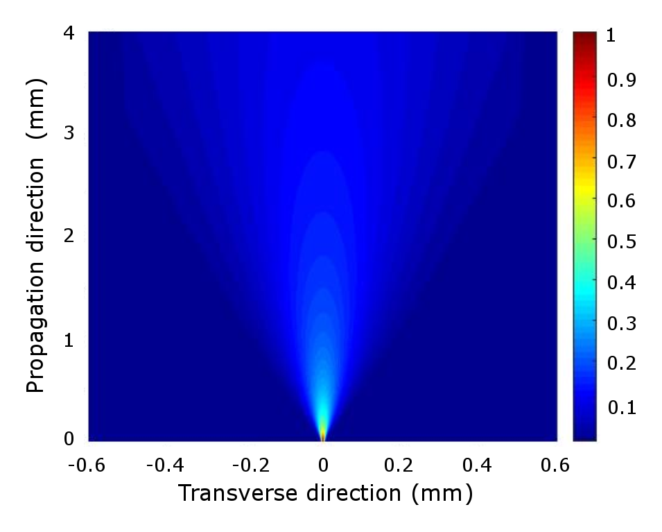
Optical losses have been evaluated with numerical methods aimed at calculating the cavity reflection coefficient (considering ideal input and output couplers). The beam was propagated from the fiber tip in free space using a finite difference beam propagation method exploiting the assumption of slowly varying fieldsyoung . Therefore, the initial field is a HE11 mode. After a length the beam was reflected by a mirror and propagated back to the fiber. The beam was than propagated through mm of fiber implementing a propagation methodfeit . The total round trip power loss is obtained by comparing the initial and final power. The parameters considered are mm, a wavelength of nm and a Corning SMF- optical fiber; with these values an overall power loss of % was calculated, corresponding to an interface limited cavity finesse of . An example of the intensity profile obtained before reflection in shown in Fig. 2.
The cavity mode volume is defined as
| (1) |
where is the normalized cavity field. We divide the integral in two domains, fiber and free space. In the former , where and is the fiber mode field radius (mfr), while in the trapping region
| (2) |
with where is the Rayleigh range. Since the beam is highly divergent Eq. 2 is an estimation. To be correct one needs to include the curvature of the wavefronts and consider the details of the mirror geometry. However, for the parameters considered in the following the para-axial approximation holdsTey and the contribution to the total mode volume coming from the free space region is only of the order of a few % thus Eq.2 provides a good estimate. By evaluating the integral in Eq. 1 we find
| (3) |
where is the length of the free space region, L is the fiber length and its refractive index. A fiber cavity allows to achieve a cavity waist of the order of the wavelength without the need work in the near concentric configuration close to the instability regiondurak .
Fiber noises and non-linear effects. We are going to assume that the environmental, electronic and classical laser noises can be controlled to a negligible level, then, the fundamental noise introduced by the fiber is the thermoptic induced phase noise, usually referred to as thermal phase noise in the fiber community. Since the intensities required for trapping the microdisk are typically rather high, possible issues could also arise from non-linear effects like Brillouin and Raman scattering.
Fiber Thermal noise. Fiber interferometers, in various configurations(Mach-Zehnder, Michelson…), constitute an active field of research especially for sensing applicationsfibersensors . The current generation of devices are approaching the fundamental thermal noise limit. This has been measured with high accuracy in a Mach-Zehnder interferometerbartolo and compared to a model initially proposed by Wanserwan . In his theory the power spectral density (PSD) of phase noise for a fiber of length can be estimated to bedong
| (4) |
where is the thermoptic coefficient, the linear expansion coefficient, is the thermal conductivity of the fiber medium and is a term that characterizes a frequency cut-off dependent on fiber geometry. It is given by:
| (5) |
In this expression , , where is the fiber outer radius, and is the thermal diffusivity. Eq. 4 describes the variance of the phase after the light field as passed through the fiber a single time, naturally, in a FFP the light bounces multiple times between the cavity mirrors so that the final total phase noise grows with an increasing finesse. In order to include thermal phase noise in the cavity dynamical equations it is simpler to consider it as detuning noise, that is , where is the speed of light.
Raman and Brillouin Scattering. For an optical field propagating in a molecular medium a fraction of the total power can be transferred to a frequency downshifted field through the interaction with the vibrational modes of the medium. Acoustical phonons are involved in Brillouin scattering while optical phonons participate in Raman scattering. For both processes the non linear dynamics becomes exponentially more relevant after a critical threshold is surpassed. In the case of Raman scattering the critical power can be estimated asagrawal where is the fiber length, is the effective mode area and m/W is the peak Raman gain. A typical value for the mode-field radius at nm is m and considering a m long fiber, than W. A similar expression can be exploited for the case of Brillouin scatteringagrawal , where m/W is the peak brillouin gain. For the parameters considered before we obtain mW. As for the case of phase noise, these values correspond to a single pass through the fiber. For a FFP the thresholds can be significantly reducedogusu ; labudde . However, lower values for have been reported in the literaturelanticq . Furthermore, stimulated Brillouin scattering is one of the most important limiting factors in high power fiber lasers and, as such, increasing its threshold is a highly researched topic. The mainstream approach relies on the introduction of non-uniformities in the fiber to achieve spectral broadening of the Brillouin gain spectrum, thus reducing the peak value . These non-uniformities ranges from temperature gradientskova to modifications of fiber composition or geometrykoby ; evert .
Description of the model. We consider an apodized microdisk, of radius and thickness , trapped in the standing wave of the FFP close to the fiber/free-space interface; we assume a high aspect ratio in order to minimize both modifications of the Gaussian profile and scattering of the intra-cavity field. We focus on the center of mass CM degree of freedom of the microdisk along the cavity axis. The transverse confinement is typically weaker giving much lower dynamical timescales while the lowest flexural mode typically has a frequency MHz. Three beams drive the cavity: a high power trapping beam at and two low power beams at to cool and detect the microdisk motion. The model we are considering is, thus, an extension of that presented in Ref.tania . We add to that description an additional field and include the fiber phase noise contribution. It must be pointed out that this treatment is based on the high finesse approximation, that is, describing the optical resonance as a Lorentzian. For the finesse values that we are going to consider the difference with the Airy peak and a Lorentzian can be significant. The equation of motions are:
| (6) |
where meaning trap, cooling and meter fields. In Eqs. 6 is the coupling strength, is the field frequency, is the empty cavity detuning, is the total cavity half-linewidth, is the driving amplitude, is a weighted sum of all vacuum operators and is a detuning noise term that accounts for the fiber phase noise. This is considered to provide an uncorrelated contribution to all cavity fields, that is . The field fluctuations are uncorrelated and have the following correlation functionszoller
| (7) |
Finally, is a Brownian stochastic force with zero mean value that arises from the background gas and obeying the correlation functionzoller ; landau :
| (8) |
where is the Boltzman constant and is the viscous damping rate.
We consider and with . The steady state is readily obtained to be
| (9) |
where is the hot cavity detuning and . Upon displacement of the operators in Eqs. 6 and subsequent linearization the dynamical equations become
| (10) |
where is the optical trap frequency. In the following we will assume , , and so that represents a good approximation considerably simplifying the model since the effective optomechanical parameters are purely determined by the cooling field. Thus, by moving into Fourier space and defining
| (11) |
with which the effective mechanical parameters can be expressed as 111To simplify the notation we use and , the mechanical susceptibility is .The symmetrized displacement PSD, then, is given by
| (12) |
Eq. 12 accounts for all force noises acting on the microdisk except for recoil heating due to the trapping potential. This can be included through the substitution , where is the initial phonon number and is the recoil heating rate in which is the disk-limited cavity finessechang2 . By assuming and , where and is the effective coupling strength, the final phonon occupation number is given byvitali2
| (13) |
It is possible to exploit Eq. 13 to estimate a maximum injected cooling power before the fiber phase noise starts contributing significantly.
Phase noise introduced by the fiber can have a significant impact on detection sensitivity since it could increase the detection noise floor. This can be evaluated by looking at the homodyne PSD of the resonant meter field. By using Eqs. 10 and by defining and we can express the intra-cavity meter field as
| (14) |
By using standard input-output formalism the reflected meter field is given by ; than as usual the homodyne observable is defined as .
Results. We consider a FFP whose input coupler is held at mm from the fiber input face and a m long fiber at the end of which an ideal mirror is assumed. The fiber has a core (cladding) diameter of m and a mfrm. The system is considered to be held in a UHV environment at a pressure mbar which corresponds to a gas-damping coefficient . The cavity finesse is , which gives a MHz and a cavity half-linewidth kHz, optical losses introduced by the fiber-free space interface contribute to the overall decay channel by . The apodized microdisk has a radius of m and a thickness m. With these values the coupling parameter is MHz. The trapping frequency is chosen to be Hz which gives a trapping beam power of mW. An estimate of the optimal cooling beam power can be obtained using Eq. 13 by requiring that the phase noise contribution equals the cooling beam back-action. That is, we impose . Assuming a detuning of and a ratio we find W for our parameters. With these parameters the optical cooling rate Hz (). We consider a meter beam power of W which provides a good compromise between final phonon number occupation and peak-to-noise ratio (PNR) in the homodyne detection.
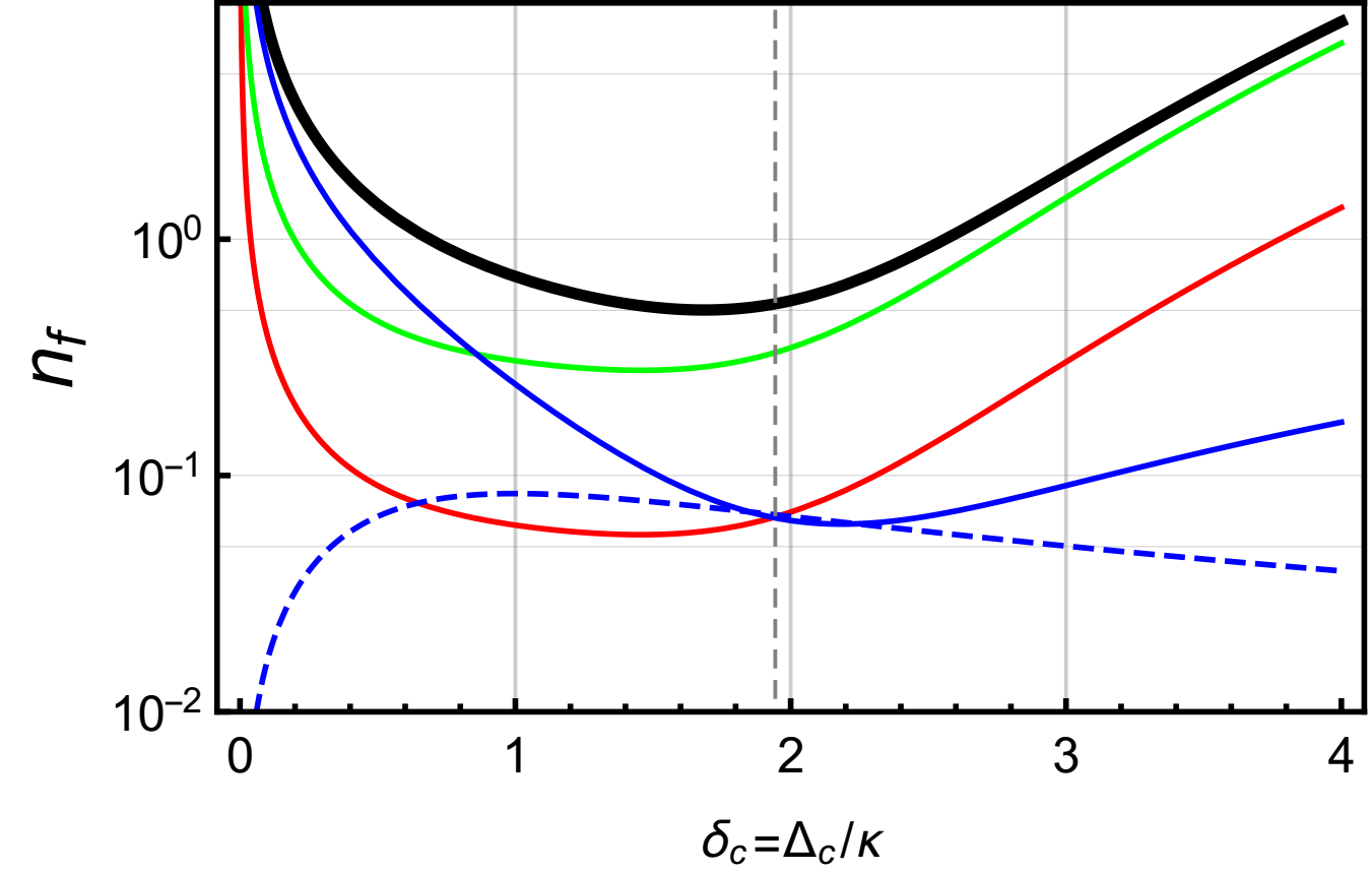
Despite the extremely low finesse a final thermal occupation number smaller than one can be obtained. This is shown in Fig.3 where we plot the final effective phonon number as a function of cooling field detuning . As imposed, fiber phase noise gives an equal contribution to the cooling field back-action, however, the limiting contribution comes from the back-action of the meter. A direct consequence is that the minimal is no longer obtained for the typical optimal detuning in the resolved sideband regime but at a slightly lower value. This is found to be for which a is obtained. Interestingly, without the meter back-action the final phonon number would be despite the contribution from the fiber phase noise.
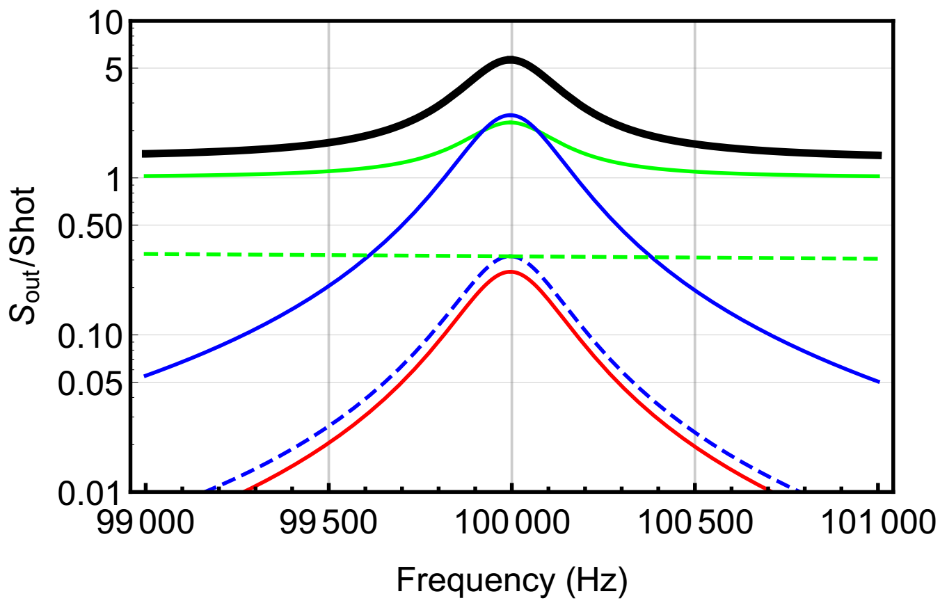
To verify the detectability of the microdisk motion we evaluated the homodyne spectra of the phase quadrature for the resonant meter field. This is show in Fig. 4 where we plot the total quadrature PSD normalized to shot noise along with all contributions. The dominant noise floor is given by the meter field shot noise with a non-negligible contribution due to fiber phase noise. We point out that this is the case since the trapping frequency for the microdisk is significantly higher than the frequency cut-off described by Eq. 5, indeed, phase noise contribution is orders of magnitude higher at low frequency.
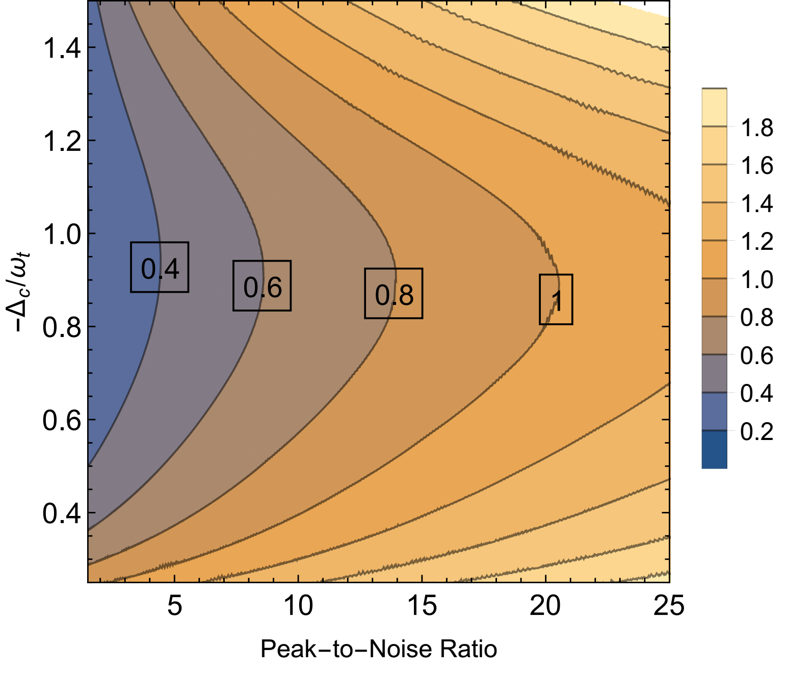
In order to emphasize the tradeoff between detectability and final occupation number, we show in Fig. 5 a contour plot of as function of cooling beam detuning and achievable peak-to-noise ratio. A final can be obtained with a high PNR with an input power of W. Interestingly, has a smooth dependance on since the system is not deeply into the resolved sideband regime.
In conclusion, we have shown that an apodized microdisk trapped in an extrinsic Fiber Fabry-Perot interferometer could be cooled down to the quantum ground state despite the extremely low finesse of the system. Thermoptic phase noise introduced by random temperature fluctuations along the fiber has been taken into account and has been shown not to constitute an intrinsic limit toward ground state cooling. Further analysis is however required. The intra-cavity power of the trapping beam is mW, this value coincides with the threshold for Brillouin scattering for a single pass in the m long fiber considered here. This implies that additional measures to significantly increase the Brillouin threshold need to be put in place. An intriguing possibility is the use of photonic crystal hollow-core fibers (HCF) due to an increased power handling capability thanks to a reduced interaction with silicaOuzounov . At the same time, a lower thermal phase noise level have been measured for HCFscranch allowing more flexibility in the parameters choice. Optical losses at the interface have already been estimated and found of the same order as for a standard single mode fiber, however, HCFs have significantly higher losses and coupling to higher modes could impact the system performance.
It has been recently proposed that a levitated sensor could be exploited to detect high frequency gravitational waves geraci1 . It has been shown that, under the right conditions, the attainable sensitivity could be more than an order of magnitude better than current interferometers like LIGO and VIRGO in the frequency range of kHz. The configuration considered here could represent a viable alternative to implement such a proposal, and will be studied in future work, with the fiber-based cavity potentially eliminating the demand for large optical mirrors. A variety of sources could produce gravitational waves at such frequencies, including signals from Black Hole superradiance minasuperrad . For example such signals can be associated with the QCD axion, a notable dark matter candidate masha1 . Such sources can also be sought after in current advanced gravitational wave interferometer observatories masha2 , and the more compact levitated-sensor approach could significantly expand the search capabilities in the higher frequency band geraci1 .
Acknowledgements The authors acknowledge funding from the EPSRC Grant No. EP/N031105/1. AP has received funding from the European Union’s Horizon 2020 research and innovation programme under the Marie Sklodowska-Curie Grant Agreement No. 749709. AG is supported by the U.S. National Science Foundation grant no. PHY-1506431 and the Heising-Simons Foundation.
References
- (1) M. Aspelmeyer, T. Kippenberg and F. Marquardt, Rev. Mod. Phys. 86, 1391 (2014).
- (2) D.W.C. Brooks et al., Nature 488, 476 (2012).
- (3) A.H. Safavi-Naeni et al., Nature 500, 185 (2013).
- (4) T.P. Purdy et al., Phys. Rev. X 3, 031012 (2013).
- (5) A. Pontin et al., arXiv:1611.00917 (2016).
- (6) A.D. Connell et al., Nature 464, 697 (2010).
- (7) J.D. Teufel et al., Nature 475, 359 (2011).
- (8) J. Chan et al., Nature 478, 89 (2011).
- (9) M. Underwood et al., Phys. Rev. A 92 , 031802(R) (2015).
- (10) P.F. Barker and M.N. Shneider, Phys. Rev. A 81, 023826 (2010); D.E. Chang et al PNAS 107, 1005 (2010); O. Romero-Isart et al., New J. Phys. 12, 033015 (2010).
- (11) T. Li et al., Nature Phys.7 , 527 (2011); J. Gieseler et al., Phys. Rev. Lett. 109 , 103603 (2012).
- (12) J. Millen et al.,Phys. Rev. Lett. 114 , 123602 (2015).
- (13) V. Jain et al., Phys. Rev. Lett. 116 , 243601 (2016).
- (14) D.E. Chang et al., New. J. Phys., 14, 045002 (2012).
- (15) Y. Chung and N. Dagli, IEEE J. Quantum Electron. 26, 1335 (1990).
- (16) M.D. Feit and J.A. Fleck, Appl. Opt. 17, 3990 (1978).
- (17) M.K. Tey et al., New. J. Phys., 11, 043011 (2009).
- (18) K. Durac et al., New. J. Phys., 16, 103002 (2014).
- (19) C.k. Kirkendall and A. Dandridge, J. Phys.D: Appl. Phys. 37, R197 (2004).
- (20) R.E. Bartolo et al.,IEEE J. Quantum Electron. 48, 720 (2012).
- (21) K.H. Wanser, Electron. Lett. 28, 53 (1992).
- (22) J. Dong, J. Huang and T. Li, Appl. Phys. Lett. 108, 021108 (2016).
- (23) G. Agrawal, Non-linear fiber optics, Academic Press (1995).
- (24) K. Ogusu, J. Opt. Soc. Am. B 20, 685 (2003).
- (25) P. Labudde et al., Opt. Commun. 32, 385 (1980).
- (26) V. Lanticq et al., Opt. Lett. 34, 1018 (2009).
- (27) V.I. Kovalev ang R.G. Harrison, Opt. Lett. 31, 161 (2006).
- (28) A. Kobyakov , Opt. Express. 13, 5338 (2005).
- (29) A. Evert et al., Opt. Express. 20, 17401 (2012).
- (30) T. Monteiro, New. J. Phys. 15, 015001 (2013).
- (31) C. W. Gardiner and P. Zoller, Quantum Noise, Springer, New York, 2000).
- (32) L. D. Landau and E. Lifshitz, Statistical Physics, Pergamon, New York, (1958).
- (33) M. Abdi et al., Phys. Rev. A, 84, 032325 (2011).
- (34) D.G. Ouzounov et al., Science, 31, 1702 (2003).
- (35) G.A. Cranch and G.A. Miller, Appl. Opt., 54, F8 (2015).
- (36) A. Arvanitaki and A. A. Geraci, Phys. Rev. Lett. 110, 071105 (2013).
- (37) A. Arvanitaki, S. Dimopoulos, S. Dubovsky, N. Kaloper, and J. March-Russell, Phys. Rev. D 81, 123530 (2010); A. Arvanitaki and S. Dubovsky, Phys. Rev. D 83, 044026 (2011).
- (38) A. Arvanitaki, M. Baryakhtar, and X. Huang, Phys. Rev. D 91, 084011 (2015).
- (39) A. Arvanitaki, M. Baryakhtar, S. Dimopoulos, S. Dubovsky, and R. Lasenby, Phys. Rev. D 95, 043001 (2017).