Passive Polarimetric Multistatic Radar Detection of Moving Targets
Abstract
We study the exploitation of polarimetric diversity in passive multistatic radar for detecting moving targets. We first derive a data model that takes into account polarization and anisotropy of targets inherent in multistatic configurations. Unlike conventional isotropic models in which targets are modeled as a collection of uniform spheres, we model targets as a collection of dipole antennas with unknown directions. We consider a multistatic configuration in which each receiver is equipped with a pair of orthogonally polarized antennas, one directed to a scene of interest collecting target-path signal and another one having a direct line-of-sight to a transmitter-of-opportunity collecting direct-path signal. We formulate the detection of moving target problem in a generalized likelihood ratio test framework under the assumption that direct-path signal is available. We show that the result can be reduced to the case in which the direct-path signal is absent. We present a method for estimating the dipole moments of targets. Extensive numerical simulations show the performance of both the detection and the dipole estimation tasks with and without polarimetric diversity.
Index Terms:
passive radar, polarimetry, multistatic, moving targetsI Introduction
I-A Overview
Passive radar senses the environment using transmitters of opportunity such as digital television stations, wideband cell-phone towers, radio transmissions, satellites, etc. The past decade has seen a sharp rise in the availability of such transmitters and with it a growing research interest in passive radar systems [1, 2, 3, 4, 5, 6, 7, 8, 9, 10, 11, 12].
The polarimetric diversity in the context of passive radar, refers to each receiver being equipped with a pair of linear and orthogonally polarized antennas. Polarimetric diversity in passive radar is important for the following reasons:
-
•
In conventional passive radars, sources, scatterers and receivers are typically assumed to be isotropic and polarimetric diversity is not considered [13, 2, 4, 5, 14, 15, 16, 17, 18, 19, 20]. Under the isotropy assumption, the vector wave equation simplifies to a scalar one. However, for the multistatic configuration the directionality/polarization of electomagnetic (EM) waves from the scatterers and antennas become increasingly important and the isotropy assumption may no longer hold.
-
•
Polarization diversity provides an additional antenna at each receiver that is polarized in an orthogonal direction. This means that even if the signal received is weak at one antenna, a relatively strong signal is received at the other ensuring the effectiveness of spatial diversity offered by the multistatic configuration.
- •
These reasons motivate the exploitation of polarimetric diversity in passive radar to produce better detection, imaging and classification performance than that of conventional non-polarimetric radar.
In this paper, we consider a multistatic configuration in which each receiver is equipped with a pair of polarimetrically diverse antennas, one of which has a direct line-of-sight to a transmitter of opportunity collecting direct-path signal and another one is directed to a scene of interest collecting target-path signal. We derive a target model and a received signal model for the scattered field from moving targets in a polarimetrically diverse configuration starting from first principle. Our derivation is based on the vector wave equation, using the dyadic Green’s function and dyadic reflectivity taking into account the linear motion of a moving target. We reduce the dyadic reflectivity to a spatially distributed dipole target model. This model is derived from the eigendecomposition of the target dyad. This decomposition induces a three colocated dipoles for the target at each spatial location with each eigenvector interpreted as a dipole moment. To reduce the size of the problem, we consider only the dominant eigenvalue/eigenvector - effectively modeling a scatterer as a single dipole with unknown dipole direction and reflectivity. We then model the receive and transmit antennas as dipole antennas to arrive at the final form of the received signal model.
We assume that the transmitted waveform and transmit antenna polarization state is unknown and formulate the moving target detection problem as a generalized likelihood ratio test. We derive the test statistic for both the case in which the direct-path signal is available and one in which it is not. We present a method of estimating target dipole direction and hence its polarization state. In [27], we analyze the performance gains in moving target detection due to polarimetric diversity in passive multistatic radar. Extensive numerical simulations show that polarimetric diversity provides superior detection performance than that of non-diverse case. Additionally, it provides information on anistoropic characteristic of scatterers that can be used for target recognition tasks.
I-B Related Work
The exploitation of polarimetry in radar application has its origins as far back as the mid 20th century [28, 29, 30, 31, 32]. However traditionally, radar polarimetry has been applied to active monostatic systems, as in polarimetric Synthetic Aperture Radar (SAR) and polarimetric SAR interferometry [25, 24, 33, 34]. In [35] multistatic polarimetric active radar has been studied for imaging of moving targets. In this work, the multistatic system exhibits polarimetric diversity in both transmitter and receiver which are both modeled as dipole antennas. The imaging scheme, however, does not extract polarization information about the target scene and consists of weighted sum of correlations between the received signal and scaled and delayed versions of the transmitted waveforms. In contrast, we study multistatic passive radar systems in which a priori knowledge on the transmitted waveforms or the polarimetric state of the transmitters of opportunity is not available. Furthermore, our objective is not only to estimate the reflectivity but also the polarization state of targets.
The dipole target model was first studied in [36]. In [33], this model is utilized and a filtered-backprojection type imaging scheme for monostatic active polarimetric SAR was developed. [33] differs from our work in that it considers imaging of static targets using an active, monostatic configuration. In addition, it constrains target dipole moments to lie on a flat ground plane. We do not assume such constraints on the dipole moment direction.
Multistatic passive radar detection problems have been studied in [2, 3, 4, 15, 16, 17]. These works do not consider polarimetric diversity nor the estimation of target’s polarization state. In [2], spatially resolved detection of stationary scatterers is studied for multiple scattering environment. This is extended to moving targets in [3, 4]. In these papers, the authors make explicit isotropic assumptions for the target, transmitters and receivers. Our GLRT-based detection scheme is similar to the one presented in [15, 16]. However, in addition to our target and data models being different, we derive our test-statistic by considering the full continuous data and noise processes. We also relax the assumption that all noise processes have a common variance.
Passive polarimetry has been explored in remote sensing applications in the optical and infrared spectrum [37]. In acoustic imaging, ambient polarized acoustic noise field is used to recover the scattering matrix [38]. In [39, 40], polarimetric diversity for passive radar detection (PCL) is studied. In this work, they experimentally assess the effectiveness of polarimetric diversity in mitigating interference on the direct-path signal. Not only is their target, data model and test-statistic different from present work, but they do not consider estimation of the target’s polarization state. In addition, we consider the case in which direct-path signal is unavailable. In [41], we studied multistatic polarimetric passive radar for a single or widely spatially separated stationary targets without direct-path signals. In the present work, we consider ground moving targets and derive spatially resolved target detection scheme along with estimation of its polarization state. In addition, we consider two cases: when the direct-path signal is available at each receiver and when no such signal is available.
I-C Organization of the Paper
The paper is organized as follows: in Section II we derive the model of scattered vector field from a moving target. In Section III, we derive the dipole target model from the eigendecomposition of dyadic permittivity. The polarimetric data model is derived in Section IV. In Section V, we use the polarimetric data model to derive the target detection and target dipole moment estimation problems. In Section VI, we present numerical simulations to demonstrate the performance of the detection and estimation methods. Section VII concludes the paper.
II Incident and Scattered Field Models
II-A Geometric Configuration of Multistatic Passive Radar
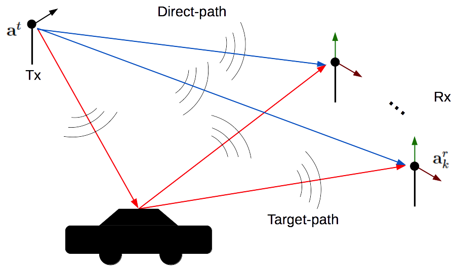
Fig. 1 depicts a typical configuration of a distributed passive radar that is of interest in this paper. We assume that there are stationary receivers distributed about a scene of interest and a single transmitter of opportunity. The location of the -th receiver is denoted as and the location of the transmitter of opportunity is denoted as . We assume that each receiver exhibits polarimetric diversity. In other words, each receiver consists of a pair of orthogonal dipole antennas receiving scattered signals from the scene of interest. Furthermore, we consider a case in which at each receiver, the direct-path111Direct-path signal is the signal received directly from the transmitter without any background scattering. signal and target-path222Target-path travels from the transmitter to the target and then scatters from the target and travels to the receiver. signal is separated. This separation can be achieved, for instance, by employing a beamforming technique on an array of receive antennas at each receiver location as in [15]. The direct-path signal is also referred to as the reference channel and the target-path signal is referred to as the surveillance channel in the literature [15, 20]. We assume that the transmitter consists of a single dipole antenna and that the dipole direction of the transmitter is not known.
II-B Scattered Field Model with Dyadic Reflectivity
Since we are interested in modeling the directionality of EM waves scattered from the target of interest, we begin with vector wave equation. We assume that the medium is reciprocal and lossless and is characterized by constant real-valued permeability, and spatially varying real-valued dyadic permittivity, where is the space of real symmetric matrices [42]. The vector wave equation is then [42]
| (1) |
where is the electric field, is the source term and is the temporal frequency.
Assumption 1.
We assume that the background medium is homogeneous and isotropic with scalar permittivity .
Under Assumption 1, we model as a perturbation of , i.e.,
| (2) |
where is a identity matrix. We assume that is compactly supported.
We can then rewrite (1) as
| (3) |
where is the wavenumber. Here, we note that where is the incident field originating from the source and is the scattered field. Using this fact, we can split (3) into two vector wave equations as
| (4) |
and
| (5) |
The solutions to the vector wave equations in (4) and (5) are given by [42]
| (6) |
and
| (7) |
where is the dyadic Green’s function333In (8), is the wave speed in free-space and is the Hessian operator. given by [42, 33]
| (8) |
(7) is the vector version of the well-known Lippmann-Schwinger equation [43]. We assume a weak surface scattering and make the Born approximation to linearize (7), arriving at
| (9) |
II-C Scattered and Incident Field From a Moving Target
In the previous section, we derived the general form of the scattered EM vector field. In this section, we derive the model for the scattered field from a moving scatterer based on (7). We begin with the following assumption.
Assumption 2.
We assume that the target at at time is moving with constant velocity . Let be location of the target at time .
From (7), we express the scattered field from the moving target in time domain as
| (10) | ||||
where is the inverse Fourier transform of (8) and
| (11) |
The model in (10) is similar to the one derived in [3] for the scalar scattered field from a moving target. We have extended this to the vector field case using the solution to the vector wave equation. This model captures anisotropic scattering from targets in multistatic configurations. In addition, consideration of the vector scattered field allows us to model the polarimetry of the scattered field.
We assume that the ground topography is known. Let a target be initially located at and moving with velocity where . Thus, we can write the reflectivity function, , that depends on in terms of that depends on , as follows:
| (12) |
where
| (13) |
We refer to as the dyadic phase space reflectivity function. Note that is equal to the dyadic permittivity, , with the third spatial variable constrained to be . We approximate (13) as
| (14) |
where is a smooth function approximating , such as a Gaussian with a small variance. Inserting (12) into (10) and integrating out the third component of and , we get
| (15) | ||||
For a typical ground moving target, the distance covered by the moving target while the transmitted signal travels from the transmitter to the target and then from the target to the receiver is much smaller than the distance from the target to the receiver. Under this assumption, we make the following first-order approximation:
| (16) |
where denotes the unit vector in the direction of . Plugging (16) into the phase in (8) we have444In (17), we made the approximation for the denominator.
| (17) | ||||
Thus, plugging (17) into the inverse Fourier transform of (6), we have
| (18) |
Now, using (18) and (17) in (15), the scattered field at the -th receiver becomes
| (19) | ||||
where
| (20) | ||||
| (21) |
Making the change of variables, we have
| (22) | ||||
where
| (23) |
In temporal Fourier domain, (22) becomes
| (24) | ||||
For any realistic ground moving target, we can safely assume that . Thus, we make the approximation that so that (24) becomes555By Cauchy-Schwarz we have that . Thus, from (20) and (21), we have that and similar for . Along with the assumption that we have .
| (25) | ||||
III Dipole Target Model
By reciprocity and the fact that is assumed to be real-valued, admits an eigendecomposition. Let , , be the eigenvalues of and , , be the corresponding eigenvectors. Then, the term in (25) can be written as
| (26) |
Note that we have suppressed and dependencies for , , and for notational simplicity. The decomposition in (26) can be interpreted as a source with colocated dipole antennas, each with dipole moment [36].
Assumption 3.
We approximate (26) with the largest eigenvalue and the corresponding eigenvector.
Let be the largest eigenvalue and be the corresponding eigenvector. Then,
| (27) |
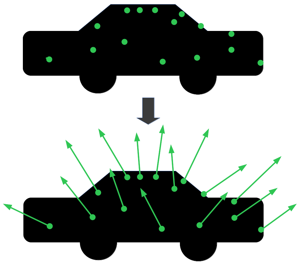
This approximation is equivalent to modeling the scatterer at by a short dipole antenna. Under this model, an extended target becomes a collection of dipole antennas. Such a dipole model for scatterers was first studied by Gustafsson in [36] and more recently by Voccola et. al. in [33, 34]. Fig. 2 illustrates the idea of the dipole target model.
IV Polarimetric Data Model
In the previous sections, we derived the models for the incident and the scattered fields from a moving target and the dipole target model approximation. In this section, we utilize these models to derive a model for the signal received by polarimetrically diverse dipole receivers due to a signal originating from a dipole transmitter and scattered by a moving target.
IV-A Model for the Incident Field from a Short Dipole Antenna
Let denote the dipole moment of the transmit antenna. Under the assumption that the length of the antenna is small compare to the distance from the antenna to the scene, we can approximate (6) as (see [34, 33, 41])
| (28) |
where is the Fourier transform of the transmitted waveform , is transmitter related terms including the antenna beam patterns and the geometric spreading factors and
| (29) |
Again, denotes the unit vector in the direction of and is a triple vector cross product term that expresses the vector projected onto the plane with normal .
IV-B The Model for the Ideal Target-Path Signal
Let and denote the dipole moments of the antennas at the -th receiver where and denote the horizontal and vertical dipole moments, respectively. Under the assumption that the lengths of the dipole antennas are small as compared to the distance from the target to the receiver, the received signal at the -th receiver can be modeled as [34, 33, 41]
| (30) | ||||
where
| (31) | ||||
| (32) | ||||
| (33) | ||||
| (34) |
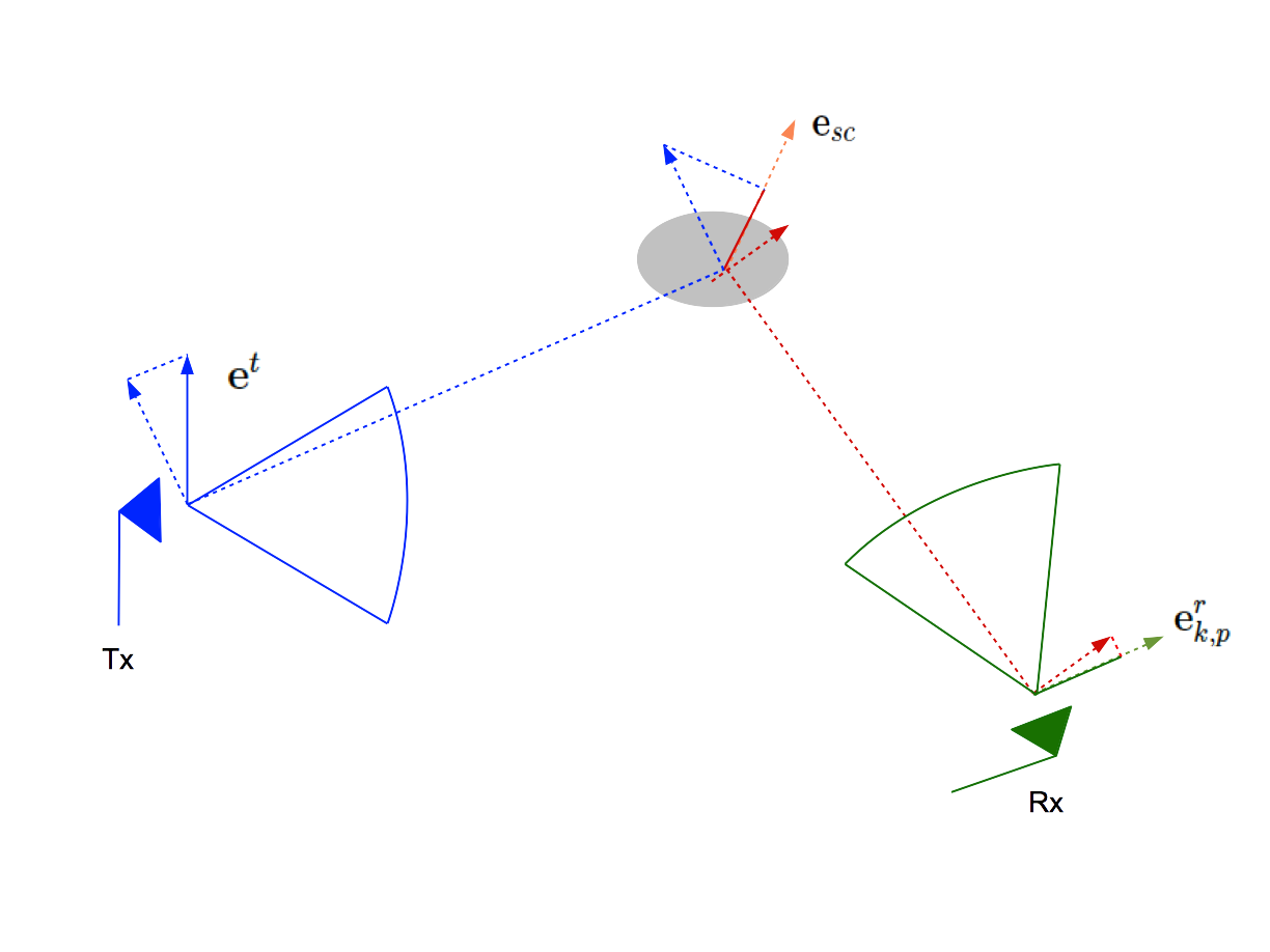
Fig. 3 illustrates the process of receiving the scattered signal from a dipole transmitter, dipole target, and dipole receiver. Note that the received signal depends on , , and . More specifically, the strengths of the signals are directly proportional to the scalar product between and and and . This implies that the dipole-target model captures the anisotropic scattering, because depends on the look direction . If is roughly parallel to , the received signal becomes weak. Conversely, if is roughly orthogonal to , the received signal becomes strong.
The are terms related to the receive antennas including the antenna beam patterns and the geometric spreading factors. We assume and are slowly varying functions of frequency, . Furthermore, we assume a narrowband (w.r.t. the center frequency, ) transmitted waveform having frequency support . Let where is a slowly varying function of such that the approximation holds. Thus, . Since , we have with bandlimitted support , .
Assumption 4.
We assume that and do not vary much within , and approximate and as constants w.r.t. .666We justify this assumption by noting that most sources of opportunities are narrowband and antenna beampatterns are close to uniform w.r.t. within the band.
With this assumption, (30) becomes
| (35) | ||||
where we make the substitution , so that . Furthermore, we make the approximation for the scalar multiple under the assumption that and .
IV-C Model for the Ideal Direct-Path Signal
The direct-path signal received at the -th receiver is proportional to the scalar product of the incident field given in (28) with the dipole moment of the receive antenna, and does not include the target related terms present in the target-path signal defined in (35). The direct-path signal is also scaled by terms related to the receiver denoted by and . Note that these terms may differ from and defined in (30) (for instance, and include a geometric spreading factor from target to the receiver that and do not). At the -th receiver, the transmitter related term, in (28) is evaluated at the receiver location, . Let , . Then, the ideal, noise-free direct-path signal at the -th receiver becomes
| (36) |
where
| (37) |
Note that in (36) we use the vector identity to make the substitution where .
IV-D Model for the Noisy Received Signals
(35) and (36) represent ideal, noise-free received signal models. In practice, however, all received signals are corrupted by noise. Thus, we model target-path and direct-path received signals as
| (38) | ||||
| (39) |
where
| (40) |
and
| (41) |
are the random noise processes present in the target-path and direct-path signals, respectively, at the -th receive antennas.
Assumption 5.
We assume that for all , is independent of for and that is independent of . Similarly, for all , is independent of for and is independent of . Furthermore, is independent of for all . Finally, we assume that all noise processes are zero-mean Gaussian white noise processes, i.e., the auto-covariances functions and for and .
We now consider the second-order statistics of all measurements. These statistics can be succinctly expressed as matrix-valued covariance functions by first considering the following random vectors:
| (42) |
and
| (43) |
Next, we define the following matrix valued covariance functions
| (44) |
and
| (45) |
By Assumption 5 on the noise processes, and can be expressed as
| (46) |
and
| (47) |
where and are diagonal matrices that do not depend on .
Finally, we assume that and are non-singular. Since and are both diagonal matrices, this assumption is satisfied so long as no or is identically zero.
V Target Detection and Target Dipole Estimation
We first set up a binary hypothesis test and next address it via generalized likelihood ratio test (GLRT). The solution to the GLRT leads to both the test-statistic for the detection task as well as a method for estimating the dipole moment of the target.
V-A Target Detection
We consider two detection problems: one where the direct-path signal is available and another problem where it is not. We present a unified framework to address both problems.
For the rest of this section we assume that we have a single point target. For multiple targets, if we assume that scattered signal from each target can be separated in time, i.e., the targets are sparsely distributed in space so that their respective ranges to each receiver are far apart, then we can apply time-domain windows to the data and treat each return separately as single point targets.
For a point target located at and moving with velocity , where and are constants. Thus, (35) becomes
| (48) |
where and .
We hypothesize that the point target is located at moving with velocity and let .We consider the vectorized measurements
| (49) |
and
| (50) |
Now, let
| (51) |
and
| (52) |
where denotes a block diagonal matrix with being a identity matrix.
Let
| (53) | ||||
| (54) |
In addition to target detection, we are interested in estimating up to a scaling factor to eventually estimate the target dipole, . Note that the transmitter term is included in . However, since is merely a scaling term, it neither affects the solution to the target detection problem nor estimation of the target dipole.
Given (36), (48),(51), (52), (53), and (54), for each hypothesized location and velocity pair, , we address the detection problem as the following test of hypothesis:
| (55) | ||||
In (55), we assume that direct-path received signals are available. If they are not, we can omit in the formulation or, equivalently, set them equal to zero.
Since both and are unknown, we address the hypothesis test in (55) within the GLRT framework and write the test-statistic as follows:
| (56) |
where and are probability measures for the stochastic processes under and , respectively, given . Thus, the GLRT is the ratio of the maximum likelihood estimates (MLEs) of and using the Radon-Nicodym derivatives of and . Under the noise assumption in Assumption 5, we have Gaussian pdfs for each under and .
Theorem 1 (Direct-path signal available.).
Proof.
See Appendix -A. ∎
If the direct-path signal is unavailable, e.g. because it is not collected, we set in the binary hypothesis problem (55). The solution to this modified problem is given by the following corollary to Theorem 1.
Corollary 1 (Direct-path signal is not available).
Proof.
See Appendix -D. ∎
V-B Estimation of Dipole Direction
Let be the eigenvector of corresponding to its largest eigenvalue. By (78), we see that is the estimate of up to a scalar. Now, since is block diagonal,
| (65) |
Then, by (65) and (72), can be written as
| (66) |
where is the estimate of up to a scalar. Hence, by the definition of in (54), it follows that can be approximated by unit vector in the direction of where is the Moore-Penrose pseudoinverse of
| (67) |
When no direct-path signal is available, by Corollary 1, we can restrict our attention to eigenvector corresponding to the maximum eigenvalue of . Let be that eigenvector. Then, by similar reasoning as above, is the estimate of . Thus, we can again approximate by the unit vector in the direction of .
VI Numerical Simulations
We evaluate the performance of the GLRT-based spatially resolved detection and dipole moment estimation using simulated data. Specifically, we compare the performance between the set up with and without polarimetric diversity. The effect of polarimetric diversity depends on the spatial location of the antennas. We further evaluate the effect of spatial diversity on the detection performance with and without polarimetric diversity. We also compare the performance due to polarimetric diversity with and without direct-path signal.
VI-A The Configuration for Simulations
The configuration we use in all simulation is as follows: A single transmitter is located at km from the scene center transmitting an MHz bandwidth signal. The scene is a m flat ground topography. All receivers lie on a circle of radius km from the scene’s center on the ground plane, all at km above the scene.
The transmitted waveforms are linearly polarized in a single direction with center frequency of GHz. The dipole moment of the transmit antenna is parallel to the ground plane in all cases. Two linearly polarized dipole antennas, labeled and are placed at each receiver. The dipole moment of each receiver’s -polarized antenna is parallel to the ground and points in the direction , where is the azimuth angle of the -th receiver location relative to the -axis. For the -polarized receive antennas, the dipole moment directions all point upwards in the -axis direction, i.e. . Only the -polarized receive antennas are used for the case in which there is no polarization diversity present in the receivers. Fig. 4 illustrates the simulation setup.
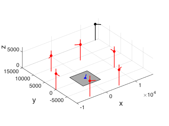
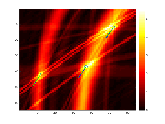
Fig. 5 shows an example test-statistic image for point targets. The plot also shows the dipole moment directions of each target (solid blue line at each target) and its estimated dipole moment (yellow dashed line at each target). Average target-path signal SNR and average direct-path signal SNR were both kept at dB, and receivers were used with samples.
VI-B Description of the Experiements
The numerical simulations presented in this section is categorized into two cases:
-
1.
The effect of polarization diversity on target detection task.
-
2.
The effect of polarization diversity on target dipole moment estimation.
We study the detection task via probability of detection as our metric. We present three subsets of simulated experiments for the detection task.
-
1.
No spatial diversity: Single receiver case with direct-path signals.
-
2.
Limited spatial diversity: Two receiver case with and without direct-path signals.
-
3.
Full spatial diversity: Six receivers surrounding the scene.
In first two scenarios, we limit the spatial diversity to focus on the effect of polarization diversity. The first scenario presents a case with single receiver in which we compare case with polarization diversity and without where direct-path signal is available in both cases. In order to compare with the case without direct-path signal, in the second scenario we place two receivers about the scene. Lastly, we examine the case with full spatial diversity and evaluate the detection performance therein. In the first two scenarios, objective is to show polarization diversity can improve detection performance when spatial diversity is limited. The third scenario, we aim to show that polarization diversity can help to fully exploit spatial diversity.
VI-C Target Detection Performance
To evaluate the target detection performance using the GLRT-based approach stated in Theorem 1, we numerically estimate the probability of detection under constant false alarm rate (CFAR) of . The threshold values that achieve the CFAR are determined numerically using realizations of noise under the null hypothesis, . The is held constant for each experiment. The noise processes added to each received signal are all assumed to have common variances of for target-path signals and for direct-path signals. In other words, we set and where is the identity matrix. The variances are determined by the average signal SNRs.
VI-C1 Single receiver with direct-path signal
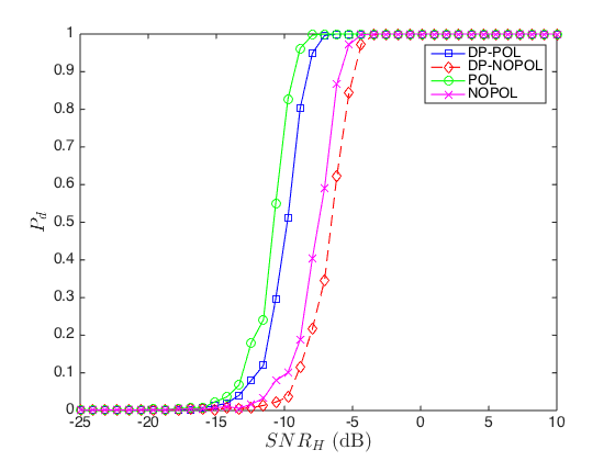
We begin our investigation with the simplest scenario of a single receiver with direct-path signal available. In this scenario, we only compare cases with direct-path signal between polarization diversity and no polarization diversity. We look at two cases, with high direct-path signal SNR (10 dB) and with low direct-path signal SNR (-30 dB). The receiver was placed so that -polarized and -polarized target-path signals had roughly equivalent SNRs. The simulation results are shown in Fig. 6.
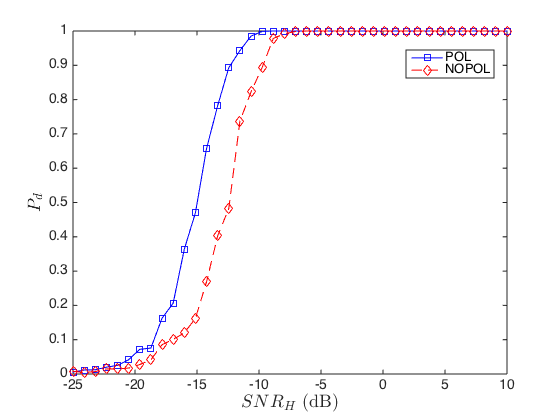
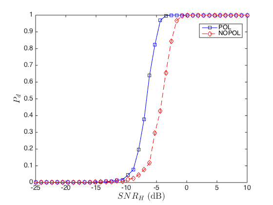
In Fig. 6, we see improvement in detection performance for polarimetrically diverse case over no polarimetric diversity, with both high direct-path SNR and low direct-path SNR. The improvement is similar in both cases. The high direct-path SNR primarily functions to shift the probability of detection graph. It also changes the slope of the probability of detection graph so that the degradation in probability of detection as function of target-path signal SNR is more gradual. Using fixed as a figure of merit, we see a dB improvement in received signal SNR. If we fix for case without polarimetric diversity, we see that there is improvement of in probability of detection with polarimetric diversity for high direct-path SNR case and improvement of in probability of detection for low direct-path SNR case.
VI-C2 Two receiver with and without direct-path signal
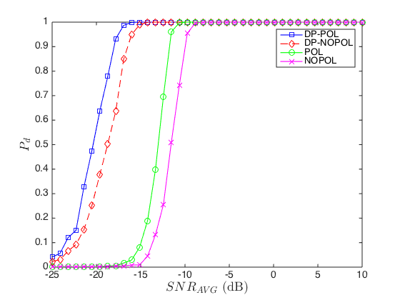
In this subsection, we present simulations with limited spatial diversity, with two receivers. By having two receivers, we can in edition compare scenarios between case with direct-path signals available and case without. We again look at case with high direct-path SNR ( dB) and low direct-path SNR ( dB). Fig. 7 shows the result.
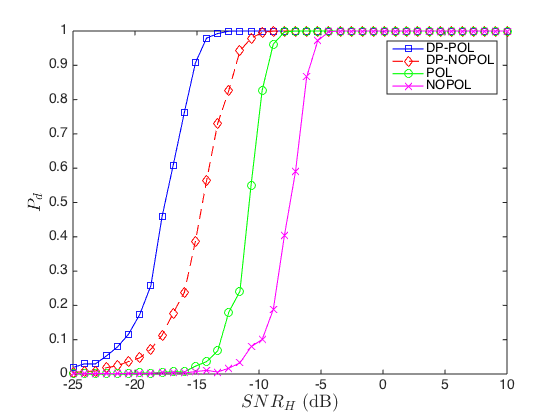
We see improvement in detection performance for polarimetrically diverse case over no polarimetric diversity, with both high direct-path SNR and low direct-path SNR. The improvement is again similar in both cases. For fixed as a figure of merit, we see a and dB improvement in average received signal SNR for case with high average direct-path SNR and low average direct-path SNR, respectively. Without direct-path, the improvement is dB. If we fix for case without polarimetric diversity, we see that there is improvement of about in probability of detection with polarimetric diversity for both high direct-path SNR, low direct-path SNR, and without direct-path signal cases. Furthermore, we see that with low direct-path SNR, the detection performance degrades to be comparable to, in fact, a bit worse than that of case without direct-path signals available.
VI-C3 Full spatial diversity: receivers
The final scenario we examined was with full spatial diversity using receivers equally spaced on the circle around the scene. For this experiment, we show results for different average direct-path signal SNRs. Fig. 8 shows the results of the probability of detection the different average direct-path SNR cases. Comparing Fig. 8(a) and Fig.8, we see that the improvement in the probability of detection graph is minimal with growing high direct-path SNRs.
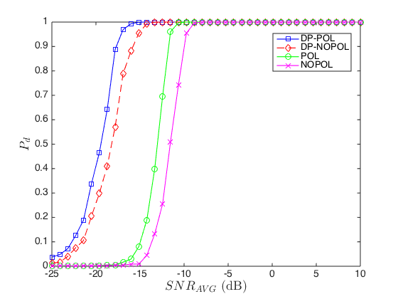
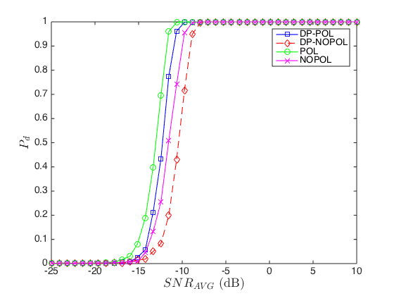
For fixed as a figure of merit, we see a dB improvement in average received signal SNR is observed for high average direct-path SNR ( dB), dB improvement with average direct-path SNR at dB and dB for low average direct-path SNR ( dB). Without direct-path, the improvement is dB. Fixing for case without polarimetric diversity, we see that there is improvement of about in probability of detection with polarimetric diversity for dB average direct-path SNR, for dB average direct-path SNR, and for dB average direct-path SNR. For case without direct-path the improvement in is .
VI-D Numerical Simulation of Target Dipole Moment Estimation
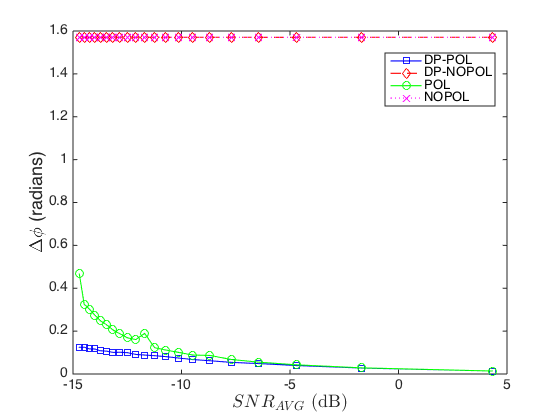
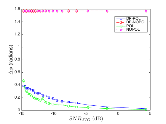
We also examine the performance of dipole moment estimation. We again use receivers equally spaced on a circle about the center of the scene. The performance criteria used is the the angle between the true dipole moment and the estimated one. Specifically, we use realizations of noise and use the sample average of the estimated angles, labeled , in radians, between the true dipole moment and the estimated one as the final performance criteria. We repeated this process for various target-path noise levels. Fig. 9 shows the resulting graph of vs. average target-path signal SNRs (). Note that non-diverse cases completely fails to accurately estimate the dipole moment. Namely, is close to for all values. This is due to the fact that for the non-diverse case, estimated dipole moment all have a dominant component along the -axis. The -axis component of the target dipole moment cannot be estimated accurately since it lies in the orthogonal complement of the subspace spanned by the dipole moments of the -polarized receive antennas as they all lie in a plane parallel to the ground plane. Furthermore, in the case of dipole moment estimation, high level of direct-path noise degrades the estimation performance to the extent that having only the target-path signal results in better estimates. This is due to the fact that, although the direct-path signals do not contain information about the dipole moment of the target directly, the estimation of , i.e. the eigenvector, does depend on the direct-path signals.
VII Conclusions and Future Works
In this paper, we derived from first principles, a novel polarimetric data model for moving target that takes into account anisotropic scattering. This model represents a target as a spatially distributed collection of dipole antennas. We considered a bistatic scenario with a single transmitter of opportunity equipped with a dipole antenna with unknown dipole moment direction and multiple receivers equipped with a pairs of orthogonally polarized dipole antennas. We address the target detection with and without direct-path signal in a unified GLRT framework and derived a method to estimate the dipole moment of the target. The detection test-statistic is given in terms of the maximum eigenvalues of whitened data correlation matrices. For the case with the direct-path signal, the test-statistic is the difference between the maximum eigenvalues of full data correlation matrix (with both target-path and direct-path received signals) and the correlation matrix for the direct-path signals only. When direct-path signals are not available, the test-statistic reduces to the maximum eigenvalue of the target-path correlation matrix. The dipole moment estimation was derived from the eigenvector associated with the maximum eigenvalue of the data correlation matrix. This estimation method falls out naturally from the solution to a generalized eigenvalue problem from the GLRT framework.
In addition, through series of numerical simulations, we show that polarimetric diversity helps in both the detection and dipole estimation tasks. Specifically, numerical simulations show that polarimetric diversity improves the probability of detection under constant false alarm rate. The improvement was observed both with limited spatial diversity and full spatial diversity. For the dipole estimation, we further show that, without diversity, full -dimensional estimation of the dipole moment is untenable due to non-trivial null space. We further showed that availability of direct-path signal generally improves both the detection and the estimation tasks.
In the companion paper [27], we provide a mathematical analysis of the detection performance. For further extension of this work, we may add structured noise such as clutter and examine the detection test-statistics under such scenario. An alternative to GLRT could also be employed for the detection task, such as a Bayesian framework.
References
- [1] Q. Wang, Y. Lu, and C. Hou, “An experimental wimax based passive radar study,” in Microwave Conference, 2009. APMC 2009. Asia Pacific, Dec 2009, pp. 1204–1207.
- [2] L. Wang, I.-Y. Son, and B. Yazici, “Passive imaging using distributed apertures in multiple-scattering environments,” Inverse Problems, vol. 26, 2010.
- [3] L. Wang and B. Yazici, “Passive imaging of moving targets exploiting multiple scattering using sparse distributed apertures,” Inverse Problems, vol. 28, no. 12, p. 125009, 2012. [Online]. Available: http://stacks.iop.org/0266-5611/28/i=12/a=125009
- [4] ——, “Passive imaging of moving targets using sparse distributed apertures,” SIAM Journal on Imaging Sciences, vol. 5, no. 3, pp. 769–808, 2012.
- [5] L. Wang, C. Yarman, and B. Yazici, “Doppler-hitchhiker: A novel passive synthetic aperture radar using ultranarrowband sources of opportunity,” Geoscience and Remote Sensing, IEEE Transactions on, vol. 49, no. 10, pp. 3521–3537, Oct 2011.
- [6] H. Griffiths and C. Baker, “Passive coherent location radar systems. part 1: performance prediction,” Radar, Sonar and Navigation, IEE Proceedings -, vol. 152, no. 3, pp. 153–159, June 2005.
- [7] C. Baker, H. Griffiths, and I. Papoutsis, “Passive coherent location radar systems. part 2: waveform properties,” Radar, Sonar and Navigation, IEE Proceedings -, vol. 152, no. 3, pp. 160–168, June 2005.
- [8] B. Dawidowicz, P. Samczynski, M. Malanowski, J. Misiurewicz, and K. Kulpa, “Detection of moving targets with multichannel airborne passive radar,” Aerospace and Electronic Systems Magazine, IEEE, vol. 27, no. 11, pp. 42–49, November 2012.
- [9] P. Krysik and K. Kulpa, “The use of a gsm-based passive radar for sea target detection,” in Radar Conference (EuRAD), 2012 9th European, Oct 2012, pp. 142–145.
- [10] S. Wacks and B. Yazici, “Passive synthetic aperture hitchhiker imaging of ground moving targets - part 1: Image formation and velocity estimation,” Image Processing, IEEE Transactions on, vol. 23, no. 6, pp. 2487–2500, June 2014.
- [11] C. E. Yarman, L. Wang, and B. Yaziciı, “Doppler synthetic aperture hitchhiker imaging,” Inverse Problems, vol. 26, no. 6, p. 065006, 2010. [Online]. Available: http://stacks.iop.org/0266-5611/26/i=6/a=065006
- [12] E. Mason, I.-Y. Son, and B. Yazici, “Passive synthetic aperture radar imaging using low-rank matrix recovery methods,” IEEE Journal of Selected Topics in Signal Processing, 2015, to appear.
- [13] I.-Y. Son, T. Varslot, C. E. Yarman, A. Pezeshki, B. Yazici, and M. Cheney, “Radar detection using sparsely distributed apertures in urban environment,” in Defense and Security Symposium. International Society for Optics and Photonics, 2007, pp. 65 671Q–65 671Q.
- [14] D. Hack, L. Patton, A. Kerrick, and M. Saville, “Direct cartesian detection, localization, and de-ghosting for passive multistatic radar,” in Sensor Array and Multichannel Signal Processing Workshop (SAM), 2012 IEEE 7th, June 2012, pp. 45–48.
- [15] D. E. Hack, L. K. Patton, B. Himed, and M. A. Saville, “Detection in passive MIMO radar networks,” IEEE Transactions on Signal Processing, vol. 62, no. 11, pp. 2999–3012, June 2014.
- [16] D. E. Hack, L. K. Patton, B. Himed, M. Saville et al., “Centralized passive mimo radar detection without direct-path reference signals,” Signal Processing, IEEE Transactions on, vol. 62, no. 11, pp. 3013–3023, 2014.
- [17] K. S. Bialkowski, S. D. Howard et al., “Generalized canonical correlation for passive multistatic radar detection,” in Statistical Signal Processing Workshop (SSP), 2011 IEEE. IEEE, 2011, pp. 417–420.
- [18] J. E. Palmer, H. A. Harms, S. J. Searle, and L. M. Davis, “Dvb-t passive radar signal processing,” Signal Processing, IEEE Transactions on, vol. 61, no. 8, pp. 2116–2126, 2013.
- [19] F. Colone, G. De Leo, P. Paglione, C. Bongioanni, and P. Lombardo, “Direction of arrival estimation for multi-frequency fm-based passive bistatic radar,” in Radar Conference (RADAR), 2011 IEEE. IEEE, 2011, pp. 441–446.
- [20] G. Cui, J. Liu, H. Li, and B. Himed, “Target detection for passive radar with noisy reference channel,” in Radar Conference, 2014 IEEE, 2014, pp. 0144–0148.
- [21] T. Webster, “Scalar and vector multistatic radar data models,” Ph.D. dissertation, Rensselaer Polytechnic Institute, Troy, NY, December 2012.
- [22] J.-S. Lee and E. Pottier, Polarimetric Radar Imaging: From Basics to Applications, 1st ed., ser. Optical Science and Engineering. Boca Raton, FL: CRC Press, 2009, vol. 143.
- [23] S. R. Cloude and E. Pottier, “A review of target decomposition theorems in radar polarimetry,” IEEE Transactions on Geoscience and Remote Sensing, vol. 34, no. 2, pp. 498–518, March 1996.
- [24] W.-M. Boerner, “Basics of sar polarimetry i,” DTIC Document, Tech. Rep., 2007.
- [25] A. Moreira, P. Prats-Iraola, M. Younis, G. Krieger, I. Hajnsek, and K. Papathanassiou, “A tutorial on synthetic aperture radar,” IEEE Geoscience and Remote Sensing, vol. 1, no. 1, pp. 6–43, March 2013.
- [26] J. A. Jackson, “Three-dimensional feature models for synthetic aperture radar and experiments in feature extraction,” Ph.D. dissertation, Ohio State University, 2009.
- [27] I.-Y. Son and B. Yazici, “Performance analysis of passive polarimetric multistatic radar detection of moving targets,” 2017, to be published.
- [28] G. Sinclair, “Modification of the radar target equation for arbitrary targets and arbitrary polarization,” Antenna Laboratory, The Ohio State Univsersity Research Foundation, Tech. Rep., 1948.
- [29] ——, “The transmission and reception of elliptically polarized waves,” Proceedings of the IRE, vol. 38, no. 2, pp. 148–151, 1950.
- [30] E. M. Kennaugh, “Polarization properties of radar reflections,” Master’s thesis, The Ohio State University, March 1952.
- [31] G. A. Deschamps, “Geometrical representation of the polarization of a plane electromagnetic wave,” Proceedings of the IRE, vol. 39, no. 5, pp. 540–544, 1951.
- [32] C. D. Graves, “Radar polarization power scattering matrix,” Proceedings of the IRE, vol. 44, no. 2, pp. 248–252, 1956.
- [33] K. Voccola, M. Cheney, and B. Yazici, “Polarimetric synthetic-aperture inversion for extended targets in clutter,” Inverse Problems, vol. 29, no. 5, April 2013.
- [34] K. Voccola, “Statistical and analytical techniques in synthetic aperture radar,” Ph.D. dissertation, Rensselaer Polytechnic Institute, Troy, NY, August 2011.
- [35] T. Webster, M. Cheney, and E. L. Mokole, “Multistatic polarimetric radar data modeling and imaging of moving targets,” Inverse Problems, vol. 30, no. 3, p. 035002, 2014.
- [36] M. Gustafsson, “Multi-static synthetic aperture radar and inverse scattering,” Technical Report LUTEDX/(TEAT-7123)/1-28/(2003), 2004.
- [37] J. S. Tyo, D. L. Goldstein, D. B. Chenault, and J. A. Shaw, “Review of passive imaging polarimetry for remote sensing applications,” Applied Optics, vol. 45, no. 22, pp. 5453–5469, August 2006.
- [38] K. Wapenaar and J. Thorbecke, “On the retrieval of the directional scattering matrix from directional noise,” SIAM Journal of Imaging Science, vol. 6, pp. 322–340, 2013.
- [39] F. Colone and P. Lombardo, “Exploiting polarimetric diversity in fm-based pcl,” in Radar Conference (Radar), 2014 International. IEEE, 2014, pp. 1–6.
- [40] ——, “Polarimetric passive coherent location,” Aerospace and Electronic Systems, IEEE Transactions on, vol. 51, no. 2, pp. 1079–1097, 2015.
- [41] I.-Y. Son and B. Yazici, “Passive imaging with multistatic polarimetric radar,” in 2015 IEEE International Radar Conference, 2015.
- [42] W. C. Chew, Waves and Fields in Inhomogenous Media. Wiley-IEEE Press, 1999.
- [43] D. Colton and R. Kress, Inverse Acoustic and Electromagnetic Scattering Theory, 2nd ed. Springer, 1998.
-A Proof of Theorem 1
Define the inner product
| (68) |
and the associated norm as
| (69) |
Under the Gaussian noise assumptions in Section IV-D, we have the following log-likelihood function under
| (70) | ||||
and under
| (71) |
The (56) implies that we can then solve the MLE problem by maximizing (70) w.r.t. and maximizing (71) w.r.t. and taking their difference.
We maximize (74) first over and find in terms of , then maximize it over .
By maximizing over , we arrive at a solution given by the following Lemma.
Lemma 1.
Given (74),
| (75) |
Proof.
See Appendix -B. ∎
Using Lemma 1, we plug (75) into (74) and we arrive at
| (76) |
where
| (77) |
In Appendix -C, it is shown that maximizing (77) w.r.t. is equivalent to solving the following generalized eigenvalue problem:
| (78) |
The solution to (78) is given by . Therefore,
| (79) |
We can follow similar procedure to solve maximization of (71) and arrive at
| (80) | ||||
Noting that common scalar term is irrelevant, we arrive at our conclusion that
| (81) | ||||
-B Proof of Lemma 1
Since (74) is Fréchet differentiable we use Gâteaux derivative to differentiate (74) w.r.t . First note that
| (82) |
By definition of Gâteaux derivative we have that
| (83) | ||||
| (84) | ||||
| (85) | ||||
| (86) | ||||
| (87) |
where, in the last two lines, we used the fact that diagonal matrices commute and that is unitary for every . By similar computation, we have that
| (88) | ||||
Thus, we have
| (89) |
Setting (89) equal to zero implies the desired result.
-C Derivation of (78)
Note that is not a function of . Under the assumption that , the integrand of is Lipschitz w.r.t. . Furthermore, is continuous w.r.t. and so is given that is continuous w.r.t. . Since the domain of integration, , is compact, and the integrand continuous w.r.t. , the integrand is Lipschitz w.r.t. . Thus, by Lebesgue Dominated Convergence theorem we can interchange the integral and the gradient operator arriving at
| (90) |
We now use the product rule to evaluate the gradient of the integrand. First, we have that
| (91) |
Next, we have by the chain rule,
| (92) |
| (93) | ||||
Plugging in (93) into (90) and setting we arrive at the generalized eigenvalue problem in (78).