The complete micromagnetic characterization of asymmetrically sandwiched ferromagnetic films
Abstract
The magnetic properties of ferromagnetic thin films down to the nanoscale are ruled by the exchange stiffness, anisotropies, and the effects of magnetic fields. As surfaces break inversion symmetry, an additional effective chiral exchange is omnipresent in any magnetic nanostructure. These so-called Dzyaloshinskii-Moriya interactions (DMIs) affect all inhomogeneous magnetic state. These effects are mostly subtle, but can also be spectacular. E.g., DMIs cause a chirality selection of the rotation sense and can fix the local rotation axis for the magnetization in domain walls, But, they can stabilize also entirely different twisted magnetic structures. The chiral skyrmions a two-dimensional particle-like topological soliton is the ultimately smallest of these objects, which currently is targetted as a possible information carrier in novel spintronic devices. Observation and quantification of the chiral exchange effects provide for the salient point in understanding magnetic properties in ultrathin films and other nanostructures. An easy and reliable method to determine the Dzyaloshinksii exchange constant as materials parameter of asymmetric thin films is the crucial problem. Here, we put forth an experimental approach for the determination of the complete set of the micromagnetic parameters. Quasi-static Kerr microscopy observations of domain wall creep motion and equilibrium sizes of circular magnetic objects in combination with standard magnetometry are used to derive a consistent set of these materials parameters in polycrystalline ultrathin film systems, namely CrOx/Co/Pt stacks. The quantified micromagnetic model for these films identifies the circular magnetic objects, as seen by the optical microscopy, as ordinary bubble domains with homochiral walls. From micromagnetic calculations, the chiral skyrmions stabilized by the DMI in these films are shown to have diameters in the range 40 - 200 nm, too small to be observed by optical microscopy.
keywords:
Dzyaloshinskii-Moriya interaction, exchange parameter, quasi-static determinationChiral magnetic objects such as skyrmions[1, 2],
homochiral magnetic bubble domains[3] or homochiral
domain walls (DW)[4] promise to become new fundamental
units for logic and memory devices.[5, 6, 7, 8, 9]
The chirality of non-collinear magnetic inhomogeneities can be
predetermined by the chiral exchange, an effect of the relativistic spin-orbit effect [10, 11].
Ordinarily, this small effect only leads to a weak
canting of moments in magnetically ordered materials.
However, in certain acentric crystals the DMIs affect the magnetic order on larger
length scale and stabilize chirally twisted states, as predicted theoretically by Dzyaloshinskii [12],
and later found in cubic helimagnets like MnSi [13, 14].
The symmetry conditions for these chiral effects to occur are entirely
general, and have been formulated by Dzyaloshinskii for ferromagnetic
and antiferromagnetic media.
As a surface or an interface unavoidably breaks inversion symmetry,
these chiral effects are always present
in any magnetic nanostructure.[15, 16, 2, 17]
Recognition of the importance and ubiquity of these effects
has been slow, and experimental investigations of
chiral magnetic behavior in thin magnetic films have started only
in recent years. Early observations demonstrated
chiral magnetic spiral ground-states
in a most simple antiferromagnetic monolayer film [18],
or the selection of on handedness during the formation of
vortex states in magnetic nanodisks [19].
Current interest in the chiral exchange effects in nanostructures
is centered on their peculiar ability to stabilize localized solitonic states.
The chiral DMIs have been theoretically shown to stabilize two-dimensional
radial solitons [1, 20, 2].
These solitons are double-twisted magnetizati configurations with a unique
sense of rotation that are now called chiral magnetic skyrmions.
These multidimensional solitons are fundamentally different from ordinary
circular domains, which are the well-known magnetic bubbles [5].
The swirl-like configuration of the chiral skyrmion is described by a radial profile where neighboring spins are noncollinearly twisted, both in radial and azimuthal direction. Homochiral bubble domains consist of a homogeneously magnetized circular area confined by a homochiral DW. Although both objects have the same topological charge, a unit skyrmion number, they display different dynamical properties, stability, and susceptibility to pinning[7]. The performance of skyrmion-based devices, e.g. storage density and the operation speed will be determined by the physical nature of the specific type of the chiral object, which in turn imposes stringent requirements on the functional magnetic layer. For instance, in films with isolated free skyrmions the modulated states, like one-dimensional spiral phases and skyrmion lattice states, must be suppressed by strong uniaxial anisotropies[21], while a homochiral DMI is preserved.
Design of thin magnetic film systems carrying isolated chiral magnetic skyrmions with defined properties
requires not only breaking of inversion symmetry, but control of the strength of the chiral
DM exchange and of the magnetic anisotropies.
Promising technological material platforms supporting individual localized chiral objects even at room temperature[3, 22, 23] are multilayer system generally comprised of an ultra-thin ferromagnetic (FM) layer sandwiched between two heavy metal (HM) layers[24, 25, 26, 27, 23] or one HM and a metal oxide (MO) layer.[28, 29, 30, 31, 22] Recently, in search of chiral skyrmions in such film systems, the creation and observation of circular magnetic objects have been reported displaying a very wide range of typical diameters, e.g., from around 50 nm[32] up to 2 m[3], although experimentally determined Dzyaloshinskii constant are almost the same. The skyrmion diameter is approximately fixed by the chiral modulation length , given by the ratio of direct exchange to Dzyaloshinskii constant for the chiral DMIs. The uniaxial anisotropy and demagnetization effect modifies the profiles and size of the skyrmions to a certain extent [20]. Together with the saturation magnetization , this complete set of micromagnetic materials parameters in a thin ferromagnetic film also determines the properties of the magnetic domain walls and the magnon dynamics of the collinear ferrromagnetic state. As sufficiently anisotropic magnetic films have a collinear ground-state, the effects of chiral DMIs are hidden and can be traced only indirectly by observing their effects on non-collinear magnetization configurations and their behavior. Various approaches have been proposed, how to determine the Dzyaloshinskii constant.[33, 34, 35] By now a standard method is to measure the asymmetry of magnon dispersion in thin films. However this method requires rather high quality of the films, which is not always practiable for complex multilayered and polycrystalline films. Observations of quasi-static inhomogeneities affected by the DMIs is an alternative. Microscopic observations of wall profiles, vortex core sizes, or skyrmions as excitations are difficult, as extremely high resolution must be achieved to measure tiny differences, e.g., in a left and right handed magnetic vortex or wall section [33]. Also, it is experimentally not straighforward to stabilize DWs with different handedness in a film material.
Therefore, the method currently employed relies on
observations of DW mobility,
as the interface energy of the wall is modified by the combination
of the chiral DMI and appropriate external oblique fields [24, 25].
This method only requires magneto-optical Kerr microscopy
with the resolution of a light microscope.
This method is an experimentally appealing
and can provide a routine approach to
determine the chiral magnetic properties of candidate
platforms for studies on isolated magnetic
skyrmions.
However, it is highly indirect
and relies on a precise determination
of all other micromagnetic materials parameters.
At present, there is no agreement in reported data regarding
the strength of the DMIs and the size of skyrmions in
asymetrically sandwiched thin films, Dzyaloshinskii
constants determined by different methods are not in
agreement, and there is no consensus about various
influences of different surfaces and cappings or substrate
layers on the DMIs in asymmetric sandwiches
[28, 29, 30, 31, 36, 22].
Here, we employ the quasi-static approach by observing DW creep to determine the DMI strength. By using a modified analysis method, we show how it can be used to quantify the full set of the micromagnetic parameters. We develop a measurement routine, which in conjunction with the proper theoretical framework, allows to obtain the Dzyaloshinskii constnats from a sequence of Kerr microscopy measurements without any ambiguous assumption on the exchange constant. When the DMI strength is determined, the exchange parameter can be deduced from characteristic diameters of circular magnetic objects.
Localized homochiral objects can be identified either as skyrmions or magnetic bubbles. This can be achieved by following the scaling behavior of the object size with the ferromagnetic layer thickness.
This approach is validated on a //CrOx/Co/Pt trilayer system combining the features of (i) stacking-order inversion and (ii) a novel metal-oxide joining the family of so far investigated systems based on aluminum, magnesium and gadolinium oxide.[28, 29, 30, 31, 36, 22] In this system important technology-relevant criteria like all-electric accessibility for read-out purposes and easy film preparation are ensured from an inverted growth of the film stack (substrate/MO/FM/HM). This implies a reduced optimization effort on MO layer preparation and avoids chemical interactions at the Co/MO interface during deposition. Furthermore, CrOx is introduced as an alternative MO system, in order to clarify the existence of an enhancing contribution of MO interfaces to the DMI strength.[22, 37] The cobalt layer thickness is varied to assess the scaling properties of the DMI and homochiral magnetic objects.
From the characteristic scaling dependence of the object diameter with respect to the cobalt layer thickness, we infer that the investigated systems support homochiral bubbles, rather than skyrmions. The DMI strength in our samples has comparably small values, which can yet support homochiral magnetic textures. Remarkably, the obtained exchange stiffness in the studied sample series are significantly diminished compared to the bulk value of cobalt. We further find an unambiguous evidence that interface quality or more generally microstructural features and defects modify the effective DMI mechanism. On the other hand, no empirical evidence is found for a contribution of the Co/MO interface to the DMI strength.
Results
In the following the full sequence of measurement and analysis steps for the determination of the micromagnetic materials parameters is described.
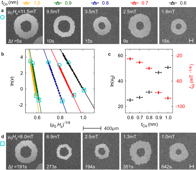
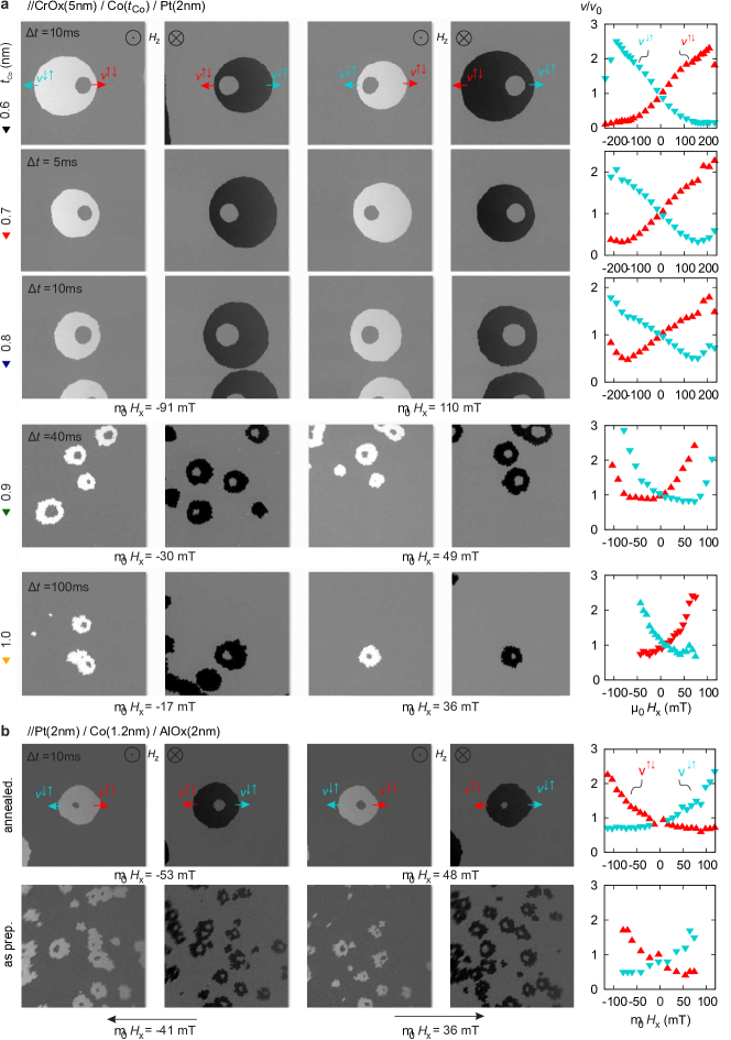
The DMI quantification method used here relies on the analysis of the field-driven evolution of domain patterns. The remagnetization process in the studied samples is generally governed by the nucleation of domains and subsequent propagation of DWs through the entire film. The DW velocities obey the creep law with the scaling parameters and (Supplementary S2). With an additionally applied field () perpendicular to the easy axis, the domain growth exhibits an asymmetric distortion as shown in figure 2a. This is a consequence of the combined modification of the DW energy by and the DMI field .[4] The DMI field is a function of all micromagnetic parameters including saturation magnetization , anisotropy energy , exchange parameter and DMI strength .
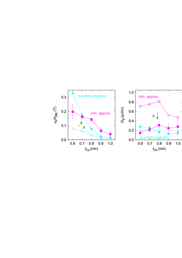
As shown in Fig. 2a the asymmetry of the domain growth is most pronounced along the axis of . By evaluating the dependence of the DW creep velocities of and DWs a -curve is recorded as plotted for different cobalt layer thicknesses in figure 2b. In an simple approximation [24, 26, 31] and only for a limited number of cases can be directly read from a usually broad minimum of the -curve. To rescale the DMI field to the Dzyaloshinskii constant for the surface-induced DMIs , a precise knowledge of all intrinsic parameters, especially the exchange constant , is required. Since is difficult to determine, usually the bulk value of =16 pJ/m for cobalt is assumed. Furthermore, ambiguities have been raised, if the method is performed in the creep regime at high in-plane fields ().[31]
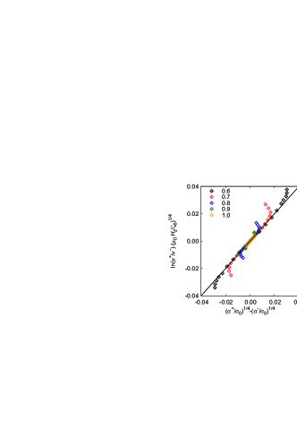
Therefore, we first derive a revised analysis that is able to determine independently from the value of the exchange stiffness , based on the original idea [24, 25] for the quantification of the DMI strength (see methods section). By focusing the evaluation of the DW velocity asymmetry on the low -field region the aforementioned ambiguities can be avoided. This allows to establish relation between the value of the Dzyaloshinskii constant and the ratio of asymmetric DW velocities which are measured in dependence on the obliquely applied field.
The relation reads
| (1) |
as derivied in Methods.
Here, only the asymmetry ratio of the DW-velocities for one field combination of and and the creep parameter are essential inputs from experiment. The two intrinsic magnetic parameters and can be obtained from elementary magnetometry.
Hence, a generally applicable approach is provided, even if no clear minimum can be obtained.
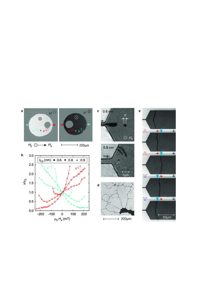
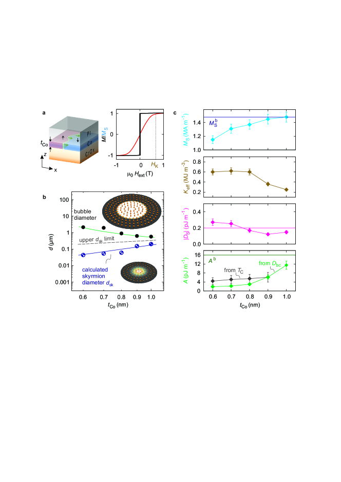
The typical size of the homochiral magnetic objects (Fig 2c) allows for the determination of one unknown parameter of the micromagnetic parameter set, here the exchange parameter . Depending on the scaling properties of the object diameter (see Fig 1b and Supplementary) the analysis has to be carried out either in the framework of isolated magnetic bubble domains[38] or skyrmion theory[39].
In the first case of magnetic bubble domains the diameter is expected to follow an inversely proportional trend to the cobalt thickness. In a correctly chosen experimental regime with fields just below the collapse field the generated objects eventually vanish at the size of the characteristic collapse diameter . According to bubble domain theory[38] the stability of the bubble is related to the ratio of the DW energy and the shape anisotropy . We point out, that in the presence of DMI the modified DW energy of has to be considered and therefore the -independent determination of is an inevitable premise. After the calculation of the stability criterion for the measured collapse diameter (see methods section) the exchange parameter remains as the only free parameter, if and are known, and can be calculated by the following relation
| (2) |
Only if a scaling of the diameter is observed, the objects classify as skyrmions. Micromagnetic simulations according to Leonov et al.[39] with known and can be performed to determine the exchange parameter by only varying until the resulting diameter matches the experimentally observed skyrmion size.
| (nm) | (MA m-1) | (MA m-1) | (MJ m-3) | (mT)1/4 | (mT) | (K) | (pJ m-1) | (nm) | (pJ m-1) | (nm) |
|---|---|---|---|---|---|---|---|---|---|---|
| 0.6 | 1.15 | 0.84 | 0.60 | 25 | 2.6 | 385 | 1.9 | 1.8 | -0.271 | 44 |
| 0.7 | 1.31 | 0.76 | 0.62 | 31 | 4.1 | 440 | 2.2 | 1.9 | -0.253 | 54 |
| 0.8 | 1.37 | 0.70 | 0.60 | 40 | 6.7 | 479 | 3.0 | 2.2 | -0.169 | 61 |
| 0.9 | 1.45 | 0.40 | 0.36 | 78 | 9.4 | 530 | 6.2 | 4.1 | -0.123 | 152 |
| 1.0 | 1.48 | 0.27 | 0.25 | 87 | 10.8 | - | 11.5 | 6.8 | -0.148 | 203 |
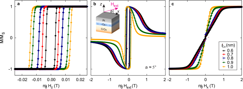
The full approach is validated on a samples series of out-of-plane magnetized //CrOx/Co()/Pt trilayers (Fig. 1a) with varying cobalt layer thicknesses prepared by sputter deposition. Elementary magnetic characterization is carried out by zero offset anomalous Hall magnetometry[40] to extract the anisotropy field from the hysteresis loops (Fig. 1a), supported by SQUID VSM for the determination of and its temperature dependence to extrapolate (Supplementary S1). All samples show perpendicular-to-plane easy axis of magnetization. Towards thinner cobalt layers significantly decreases while the effective anisotropy constant increases (see Fig. 1c).
Furthermore, we observed the formation of 360 ∘ DWs or so called winding pairs[38, 41] during field driven creep motion as well as a coherent currentinduced DW mediated by spin orbit torques as shown in Fig. 2d and e. From these two qualitative findings the presence of sufficiently strong interface-induced DMI indicative of a homochiral nature of the DWs is concluded.
The two parameters and were determined as described above. As result of the asymmetric domain growth (Fig. 2a,b) we find an almost -invariant DMI strength with a mean value of -0.200.09 pJ/m. This suggests a purely interface induced DMI mechanism for the studied //CrOx/Co()/Pt trilayer system. Since the diameter scaling was not observed (Fig. 1b), the exchange parameter was determined in the framework of magnetic bubble domain theory. As depicted in Fig. 1c increasingly significant deviations as large as an order of magnitude of from the bulk value were obtained with decreasing . The complete set of all magnetic parameters is summarized in Tab. 1.
Discussion
The DMI strength is quantified from the asymmetry ratio of DW creep velocities independently from the exchange parameter . The developed low-field analysis of the creep velocities provides a complementary quantification methods to the most commonly employed evaluation of the DMI-induced asymmetric magnon dispersion.
The DMI strength of pJ/m in //CrOx/Co/Pt trilayers is almost independent of the cobalt thickness. This indicates the interface-induced character of the DMI mechanism as previously reported in comparable systems [28, 29]. Hence the variation of the cobalt layer thickness is a common approach to tailor the effective DMI constant .
The //Pt(2nm)/Co(1.2nm)/AlOx(2nm) tilayers have large DMI values of pJ/m and pJ/m in the as-deposited and annealed state respectively. The opposite sign of the asymmetric DW expansion in //CrOx/Co/Pt and //Pt/Co/AlOx trilayers corresponds to a sign change of the Dzyaloshinskii-vector of the system. In case only the Co/Pt interface contributes to the DMI, the sign change is expected due to the inversion of the stacking order.
In following the significant difference of DMI values of the investigated samples to those reported in literature is addressed from a structural point of view. The determined DMI values in the here studied samples are considerably smaller than in other reported //Pt/Co/MO systems [28, 29, 30, 31, 36, 22].
A similar approach to that of Sagasta et al. [43] relating spin-Hall angles to the Pt resistivity to obtain correlations of microstructural properties to the spin-orbit effect strength is applied for the DMI strength.
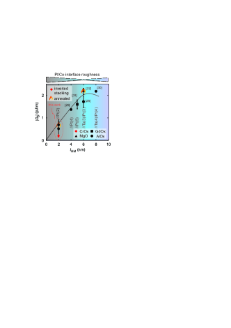
As indirect indicator of the interface roughness/quality the combined thickness of the Ta and Pt in the bottom layer is evaluated (Supplementary S4). The smoothest interfaces for these systems is expected in a thickness range between 6 and 8 nm. As the behavior in the ultra-thin limit is related to the wetting of metals on the substrate, it is inferred that the heavy metal kind is of subordinate role for the process. As long as the Pt layer is closed (i.e. 2 nm) a Ta buffer layer contributes to the smoothening of the layer. Therefore the interface roughness is related to the combined layer thickness of Pt and Ta in this discussion.
Fig. 3 shows that and are also correlated in a striking, almost linear dependence. For this comparison the reference samples with only a 2 nm thick platinum bottom layers were prepared.
The stack inversion accounts for an additional reduction of the DMI strength, as also found for Pt/Co/MgO trilayers, by a factor of 0.63 [44] due to a modified growth mode of Co/Pt bilayers on metal oxides, resulting in an even rougher interface. The clear impact of the interface quality on the DMI helps to explain the reduced DMI in the //CrOx/Co/Pt samples as a result of unfavorable growth conditions for Pt on the CrOx/Co buffer layers. The reference samples with Co grown on only 2 nm thick Pt yield are similarly rough but have slightly better interfaces. It is therefore concluded, that the DMI strength is predominated by the Pt/Co interface quality. A cartoon picture of how the roughness may influence the effective DMI constant is presented in (Supplementary S4). According to our comparison of results obtain for DMI constants in stacks with different metal oxides, a DMI contribution from the MO/Co interface is experimentally not evident (Supplementary S4).
The cobalt layer thickness in //CrOx/Co()/Pt trilayers has a strong impact not only on the saturation magnetization and the effective anisotropy but also on the exchange parameter . After employing the developed approach to determine the DMI constant independently of the exchange parameter, can be quantified from the size of circular magnetic objects. Judging from the -scaling of the diameter, the objects are identified as magnetic bubble domains. In the framework of bubble domain theory the exchange parameter can be deduced from the collapse diameter of magnetic bubble domains. For samples satisfying the condition the study of bubble domain stability offers a quasi-static alternative to methods relying on magnetization dynamics [35, 45].
As the investigations revealed the exchange parameter in the ultra thin Co layer can be diminished up to an order of magnitude compared to the cobalt bulk exchange value 16 pJ/m. This trend is supported by the approximative estimation of from the extrapolated Curie temperature. A similar reduction of was reported in a comparable system [45]. The reduction is attributed to a micro-structural origin, e.g. an increasing number of grain boundaries with decreasing cobalt layer thickness in the ultrafinely polycrystalline samples.
With the significantly diminished the expected domain wall width as well as the exchange length can be smaller than 2 nm responsible for the strong susceptibility of DWs to small pinning sites as e.g. grain boundaries.
With the determined DMI strength all samples safely remain in the limit of a collinear ferromagnetic ground-state. Due to the large anisotropy the effective DMI constants are at most 33 % of the theoretical limit or the critical DMI constant [20], for the formation of modulated spiral and skyrmion phases.
The DW energy is reduced by 1-6 % in the CrOx/Co/Pt samples due to the DMI. However, it is sufficient to induce modifications to the DW providing homochiral and Néel-type properties. Consequently the DWs obtain homochiral and Néel-type properties that are responsible for the formation of winding pairs and coherent current induced DW motion. It is therefore concluded that the magnetic bubble domains are confined by a homochiral DW.
With the complete set of micro-magnetic parameters the skyrmion diameter can be calculated. For the studied sample series the expected skyrmion diameter lies in a range between 40 and 200 nm. An upper limit for the is given by considering the bulk exchange value in the micromagnetic simulations.
Methods
Sample preparation. A sample series of perpendicularly magnetized //CrOx(5 nm)/Co()/Pt(2 nm) was magnetron-sputtered at room temperature on thermally oxidized silicon substrates with cobalt layers of varying thickness and an argon pressure of 10-3 mbar. The Pt top layer thickness of only 2 nm is sufficient to serve as a oxidation barrier providing large optical transmittance and low magnetoresistive shunting. The thin amorphous CoOx buffer layer is nonmagnetic (Supplementary). Optical lithography and subsequent Ar-Ion-Beam etching were used for patterning.
DMI quantification. For the quantification of the DMI constant we used wide field Kerr microscopy with maximum fields up to 250 mT and 20 mT. The latter is provided by a small air-core coil, which is driven by a Keysight Sourcemeter providing field pulses of defined width down to 2 ms. The DW velocities are determined from the traveled distance measured from differential Kerr-images taken from the initial and final states after application of an current pulse with the width of . Great caution was given to avoid a misalignment of the sample with respect to the hard axis field, that causes an additional component. To cancel any remaining effect of a possible misalignment the respective velocities for and DW from both up and down domains were averaged (Supplementary S2).
The quasi-static modification of the DW energy by the and can be accounted for by the introduction of in the creep law[24, 25], with . The DW energy in the presence of both fields is reduced from the Bloch wall energy to the following ratio
| (3) |
with the shape anisotropy energy scaled by the demagnetization factor of the DW. This expression is valid as long as the field combination of is smaller than the transition field from Bloch to Néel-Wall .
It is further assumed, that the pinning parameters and entering the quantity are -invariant[24].
For DWs segments situated in an (anti-)parallel ()-field configuration one can write the following system of equations
| (4) |
In Eq. (4) the creep parameter , that can be determined less accurately due to extrapolation (Supplementary S2), is eliminated, which leads to the following expression
| (5) |
Eq. (5) can be solved numerically for (Supplementary S2). With the following expansion that is valid when DW energies are only slightly changed by total effective field
| (6) |
an analytical relation between and the velocity ratio in applied fields can be derived from Eq. (5), that reads
| (7) |
Note, that the creep parameter depends on the exchange constant (and all the other micromagnetic and microstructural parameters). Here, is directly and independently determined from the experiments in the perpendicular field (). Inserting this parameter now in expressions (7) and (8) yields the DMI strength from the second set of experiments with , but small. Eq. (7) can then be rescaled to the DMI strength according to
| (8) |
With this relation the interface-induced DMI constant can be directly calculated from the logarithmic asymmetry ratio of the DW-velocities obtained at one field combination of and , the creep parameter and the two elementary magnetic parameters and . It is emphasized that this expression does not explicitly depend on the exchange parameter and is applicable only for small .
Determination of the exchange parameter. Patterning the samples into stripes of 60 m width with a constriction to 3 m in the scheme of Ref. [3] allows for the creation of circular magnetic objects. By simultaneous application of current pulses and small easy axis field (), homochiral DWs are pushed along the stripe by spin orbit torques.[46, 47] A homochiral circular object is formed due to the contraction of a domain channel in divergent currents and the expulsion from the constriction area.
In the studied system a scaling of the diameter of the generated objects as expected for skyrmions is not observed. Hence, an analysis in the framework of isolated magnetic bubble domains rather than skyrmion theory is required. The typical diameter of these bubble domains is of the order the collapse diameter of bubble domains (Supplementary S3).
According to bubble theory,[38] valid for with , the reduced collapse diameter can be derived from the ratio of DW energy to shape anisotropy satisfying the condition:
| (9) |
with the complete elliptic integrals and as function of
| (10) |
We point out that in the presence of DMI the energy of DWs with the favored chirality reads . Solving equation 9 for the exchange parameter , as the only unknown material parameter remaining, yields expression (2 Furthermore, the correct experimental conditions can be verified by calculating the expected collapse field from the condition of the force function
| (11) |
proving that the experimental fields were just slightly below the theoretical collapse field (Supplementary S3).
Note that in case of the largest cobalt thickness deviations might occur due to the violation of the condition .
Calculation of skyrmion diameters. For the analysis of skyrmion diameters, we use the micromagnetic framework with the continuous description of Dzyaloshinskii-Moriya interaction [48, 7]. As a model, we consider a thin ferromagnetic infinite plate of thickness along the -axis. Taking into account that thickness of ferromagnetic layer is smaller than characteristic magnetic length, we consider a uniform average values of magnetic parameters along the -axis. Also, we assume that the magnetostatic interaction, which is always present in the system, can be reduced to the easy-surface anisotropy, which results to the appearance of effective anisotropy coefficient . Due to this, the total micromagnetic energy density of our system will have a following form
| (12) |
where we take into account the exact form of interface-induced DMI term, is the unity vector directed perpendicular to the interface surface along the -axis. For the case of simplicity, we introduce cylindrical coordinate system with and use angular parametrization for the reduced magnetization vector . In this case, the total energy density (12) will have the following form:
| (13) |
We are looking for azimuthally symmetric solutions, which represent either skyrmion or skyrmion-bubble textures [21, 39]:
| (14) |
where is a linear function with respect to . This allows us to simplify the expression (13) and derive the total energy of a chiral axisymmetric magnetic texture:
| (15) |
The Euler-Lagrange equation for the total energy functional (15) has the following form,
| (16) |
with boundary conditions for isolated axisymmetric skyrmion:
| (17) |
The boundary value problem (16) and (17) can be solved numerically by using finite-difference method. Usually the function has spike-like shape in the vicinity of point and decays exponentially at hight distances from the skyrmion center. The characteristic size of a localized magnetization profile is usually defined as [21, 17, 39]
| (18) |
where is the inflection point of the profile .
References
- [1] Bogdanov, A. N., A. N. & Yablonsky, D. A. Thermodynamically stable vortexes in magnetically ordered crystals - mixed state of magnetics. Zhurnal Eksperimentalnoi I Teoreticheskoi Fiziki 95, 178–182 (1989).
- [2] Bogdanov, A. N. & Rößler, U. K. Chiral symmetry breaking in magnetic thin films and multilayers. Physical Review Letters 87, 037203 (2001). DOI 10.1103/PhysRevLett.87.037203.
- [3] Jiang, W. J. et al. Blowing magnetic skyrmion bubbles. Science 349, 283–286 (2015). DOI 10.1126/science.aaa1442.
- [4] Thiaville, A., Rohart, S., Jue, E., Cros, V. & Fert, A. Dynamics of dzyaloshinskii domain walls in ultrathin magnetic films. EPL 100, 57002 (2012). DOI 10.1209/0295-5075/100/57002.
- [5] Kiselev, N. S., Bogdanov, A. N., Schäfer, R. & Rößler, U. K. Chiral skyrmions in thin magnetic films: new objects for magnetic storage technologies? Journal of Physics D-applied Physics 44, 392001 (2011). DOI 10.1088/0022-3727/44/39/392001.
- [6] Parkin, S. S. P., Hayashi, M. & Thomas, L. Magnetic domain-wall racetrack memory. Science 320, 190–194 (2008). DOI 10.1126/science.1145799.
- [7] Fert, A., Cros, V. & Sampaio, J. Skyrmions on the track. Nature Nanotechnology 8, 152–156 (2013).
- [8] Soumyanarayanan, A., Reyren, N., Fert, A. & Panagopoulos, C. Emergent phenomena induced by spin-orbit coupling at surfaces and interfaces. Nature 539, 509–517 (2016). URL http://dx.doi.org/10.1038/nature19820.
- [9] Wiesendanger, R. Nanoscale magnetic skyrmions in metallic films and multilayers: a new twist for spintronics. Nature Reviews Materials 1, 16044 (2016). URL http://dx.doi.org/10.1038/natrevmats.2016.44.
- [10] Dzyaloshinskii, I. E. A thermodynamic theory of weak ferromagnetism of antiferromagnetics. Journal of Physics and Chemistry of Solids 4, 241–255 (1958). DOI 10.1016/0022-3697(58)90076-3.
- [11] Moriya, T. Anisotropic superexchange interaction and weak ferromagnetism. Phys. Rev. 120, 91–98 (1960). URL https://link.aps.org/doi/10.1103/PhysRev.120.91. DOI 10.1103/PhysRev.120.91.
- [12] Dzyaloshinskii, I. E. Theory of helicoidal structures in antiferromagnets .1. nonmetals. Soviet Physics Jetp-ussr 19, 960–971 (1964).
- [13] Bak, P. & Jensen, M. H. Theory of helical magnetic-structures and phase-transitions in mnsi and fege. Journal of Physics C-solid State Physics 13, L881–L885 (1980). DOI 10.1088/0022-3719/13/31/002.
- [14] NAKANISHI, O., YANASE, A. & HASEGAWA, A. Electronic-energy band-structure of mnsi. Journal of Magnetism and Magnetic Materials 15-8, 879–880 (1980). DOI 10.1016/0304-8853(80)90805-7.
- [15] Fert, A. Magnetic and transport properties of metallic multilayers. In Materials Science Forum, vol. 59, 439–480 (Trans Tech Publ, 1990).
- [16] Crepieux, A. & Lacroix, C. Dzyaloshinsky-moriya interactions induced by symmetry breaking at a surface. Journal of Magnetism and Magnetic Materials 182, 341–349 (1998). DOI 10.1016/S0304-8853(97)01044-5.
- [17] Rößler, U. K., Bogdanov, A. N. & Pfleiderer, C. Spontaneous skyrmion ground states in magnetic metals. Nature 442, 797–801 (2006). DOI 10.1038/nature05056.
- [18] Bode, M. et al. Chiral magnetic order at surfaces driven by inversion asymmetry. Nature 447, 190–193 (2007). DOI 10.1038/nature05802.
- [19] Im, M.-Y. et al. Symmetry breaking in the formation of magnetic vortex states in a permalloy nanodisk. Nature communications 3, 983 (2012).
- [20] Bogdanov, A. N. & Hubert, A. Thermodynamically stable magnetic vortex states in magnetic crystals. Journal of Magnetism and Magnetic Materials 138, 255–269 (1994). DOI 10.1016/0304-8853(94)90046-9.
- [21] Butenko, A. B., Leonov, A. A., Rossler, U. K. & Bogdanov, A. N. Stabilization of skyrmion textures by uniaxial distortions in noncentrosymmetric cubic helimagnets. Physical Review B 82, 052403 (2010). DOI 10.1103/PhysRevB.82.052403.
- [22] Boulle, O. et al. Room-temperature chiral magnetic skyrmions in ultrathin magnetic nanostructures. Nature Nanotechnology 11, 449 (2016). DOI 10.1038/nnano.2015.315.
- [23] Woo, S. et al. Observation of room-temperature magnetic skyrmions and their current-driven dynamics in ultrathin metallic ferromagnets. Nature Materials 15, 501 (2016). DOI 10.1038/NMAT4593.
- [24] Je, S.-G. et al. Asymmetric magnetic domain-wall motion by the dzyaloshinskii-moriya interaction. Physical Review B 88, 214401 (2013). DOI 10.1103/PhysRevB.88.214401.
- [25] Hrabec, A. et al. Measuring and tailoring the dzyaloshinskii-moriya interaction in perpendicularly magnetized thin films. Physical Review B 90, 020402 (2014). DOI 10.1103/PhysRevB.90.020402.
- [26] Lavrijsen, R. et al. Asymmetric magnetic bubble expansion under in-plane field in pt/co/pt: Effect of interface engineering. Physical Review B 91, 104414 (2015). DOI 10.1103/PhysRevB.91.104414.
- [27] Di, K. et al. Direct observation of the dzyaloshinskii-moriya interaction in a pt/co/ni film. Physical Review Letters 114, 047201 (2015). DOI 10.1103/PhysRevLett.114.047201.
- [28] Belmeguenai, M. et al. Interfacial dzyaloshinskii-moriya interaction in perpendicularly magnetized pt/co/alox ultrathin films measured by brillouin light spectroscopy. Physical Review B 91, 180405 (2015). DOI 10.1103/PhysRevB.91.180405.
- [29] Cho, J. et al. Thickness dependence of the interfacial dzyaloshinskii-moriya interaction in inversion symmetry broken systems. Nature Communications 6, 7635 (2015). DOI 10.1038/ncomms8635.
- [30] Kim, N. H. et al. Improvement of the interfacial dzyaloshinskii-moriya interaction by introducing a ta buffer layer. Applied Physics Letters 107, 142408 (2015). DOI 10.1063/1.4932550.
- [31] Vanatka, M. et al. Velocity asymmetry of dzyaloshinskii domain walls in the creep and flow regimes. Journal of Physics-condensed Matter 27, 326002 (2015). DOI 10.1088/0953-8984/27/32/326002.
- [32] Legrand, W. et al. Room-temperature current-induced generation and motion of sub-100 nm skyrmions. Nano Letters 17, 2703–2712 (2017). DOI 10.1021/acs.nanolett.7b00649.
- [33] Butenko, A., Leonov, A., Bogdanov, A. & Rößler, U. Theory of vortex states in magnetic nanodisks with induced dzyaloshinskii-moriya interactions. Physical Review B 80, 134410 (2009).
- [34] Cortes-Ortuno, D. & Landeros, P. Influence of the dzyaloshinskii-moriya interaction on the spin-wave spectra of thin films. Journal of Physics-condensed Matter 25, 156001 (2013). DOI 10.1088/0953-8984/25/15/156001.
- [35] Langer, M. et al. Parameter-free determination of the exchange constant in thin films using magnonic patterning. Applied Physics Letters 108, 102402 (2016). DOI 10.1063/1.4943228.
- [36] Di, K. et al. Asymmetric spin-wave dispersion due to dzyaloshinskii-moriya interaction in an ultrathin pt/cofeb film. Applied Physics Letters 106, 052403 (2015). DOI 10.1063/1.4907173.
- [37] Belabbes, A., Bihlmayer, G., Bluegel, S. & Manchon, A. Oxygen-enabled control of dzyaloshinskii-moriya interaction in ultra-thin magnetic films. Scientific Reports 6, 24634 (2016). DOI 10.1038/srep24634.
- [38] Hubert, A. & Schäfer, R. Magnetic Domains: The Analysis of Magnetic Microstructures. (Berlin: Springer, 1998).
- [39] Leonov, A. O. et al. The properties of isolated chiral skyrmions in thin magnetic films. New Journal of Physics 18, 065003 (2016). DOI 10.1088/1367-2630/18/6/065003.
- [40] Kosub, T., Kopte, M., Radu, F., Schmidt, O. G. & Makarov, D. All-electric access to the magnetic-field-invariant magnetization of antiferromagnets. Physical Review Letters 115, 097201 (2015). DOI 10.1103/PhysRevLett.115.097201.
- [41] Benitez, M. J. et al. Magnetic microscopy and topological stability of homochiral neel domain walls in a pt/co/alox trilayer. Nature Communications 6, 8957 (2015). DOI 10.1038/ncomms9957.
- [42] Slepicka, P., Svorcik, V., Slouf, M., Rybka, V. & Spirkova, M. Characterization of metal nanolayers sputtered on poly(ethyleneterephtalate). Optoelectronics and Advanced Materials-rapid Communications 2, 153–160 (2008).
- [43] Sagasta, E. et al. Tuning the spin hall effect of pt from the moderately dirty to the superclean regime. Phys. Rev. B 94, 060412 (2016). URL https://link.aps.org/doi/10.1103/PhysRevB.94.060412. DOI 10.1103/PhysRevB.94.060412.
- [44] Lee, J. M. et al. All-electrical measurement of interfacial dzyaloshinskii-moriya interaction using collective spin-wave dynamics. Nano Letters 16, 62–67 (2016). DOI 10.1021/acs.nanolett.5b02732.
- [45] Nembach, H. T., Shaw, J. M., Weiler, M., Jue, E. & Silva, T. J. Linear relation between heisenberg exchange and interfacial dzyaloshinskii-moriya interaction in metal films. Nature Physics 11, 825 (2015). DOI 10.1038/NPHYS3418.
- [46] Emori, S., Bauer, U., Ahn, S.-M., Martinez, E. & Beach, G. S. D. Current-driven dynamics of chiral ferromagnetic domain walls. Nature Materials 12, 611–616 (2013). DOI 10.1038/NMAT3675.
- [47] Ryu, K.-S., Yang, S.-H., Thomas, L. & Parkin, S. S. P. Chiral spin torque arising from proximity-induced magnetization. Nature Communications 5, 3910 (2014). DOI 10.1038/ncomms4910.
- [48] Rohart, S. & Thiaville, A. Skyrmion confinement in ultrathin film nanostructures in the presence of dzyaloshinskii-moriya interaction. Physical Review B 88, 184422 (2013). DOI 10.1103/PhysRevB.88.184422.
- [49] Nozaki, T., Oida, M., Ashida, T., Shimomura, N. & Sahashi, M. Temperature-dependent perpendicular magnetic anisotropy of co-pt on cr2o3 antiferromagnetic oxide. Applied Physics Letters 103, 242418 (2013). DOI 10.1063/1.4850533.
- [50] Iunin, Y. L. et al. Asymmetric domain nucleation and unusual magnetization reversal in ultrathin co films with perpendicular anisotropy. Physical Review Letters 98, 117204 (2007). DOI 10.1103/PhysRevLett.98.117204.
- [51] Pizzini, S. et al. Chirality-induced asymmetric magnetic nucleation in pt/co/alox ultrathin microstructures. Physical Review Letters 113, 047203 (2014). DOI 10.1103/PhysRevLett.113.047203.
- [52] Metaxas, P. J. et al. Creep and flow regimes of magnetic domain-wall motion in ultrathin pt/co/pt films with perpendicular anisotropy. Physical Review Letters 99, 217208 (2007). DOI 10.1103/PhysRevLett.99.217208.
- [53] Gorchon, J. et al. Pinning-dependent field-driven domain wall dynamics and thermal scaling in an ultrathin pt/co/pt magnetic film. Physical Review Letters 113, 027205 (2014). DOI 10.1103/PhysRevLett.113.027205.
- [54] Lemerle, S. et al. Domain wall creep in an ising ultrathin magnetic film. Phys. Rev. Lett. 80, 849–852 (1998). URL https://link.aps.org/doi/10.1103/PhysRevLett.80.849. DOI 10.1103/PhysRevLett.80.849.
- [55] Kabanov, Y. P. et al. In-plane field effects on the dynamics of domain walls in ultrathin co films with perpendicular anisotropy. Ieee Transactions on Magnetics 46, 2220–2223 (2010). DOI 10.1109/TMAG.2010.2045740.
- [56] Kim, D.-Y., Kim, D.-H., Moon, J. & Choe, S.-B. Determination of magnetic domain-wall types using dzyaloshinskii-moriya-interaction-induced domain patterns. Applied Physics Letters 106, 262403 (2015). DOI 10.1063/1.4922943.
- [57] Soucaille, R. et al. Probing the dzyaloshinskii-moriya interaction in cofeb ultrathin films using domain wall creep and brillouin light spectroscopy. Phys. Rev. B 94, 104431 (2016). URL https://link.aps.org/doi/10.1103/PhysRevB.94.104431. DOI 10.1103/PhysRevB.94.104431.
- [58] Jue, E. et al. Chiral damping of magnetic domain walls. Nature Materials 15, 272 (2016). DOI 10.1038/NMAT4518.
- [59] Melo, L. L., Vaz, A. R., Salvadori, M. C. & Cattani, M. Grain sizes and surface roughness in platinum and gold thin films. Ismanam 2003: Metastable, Mechanically Alloyed and Nanocrystalline Materials 20-21, 623–628 (2004).
- [60] Tacchi, S. et al. Interfacial dzyaloshinskii-moriya interaction in films: Effect of the heavy-metal thickness. Phys. Rev. Lett. 118, 147201 (2017). URL https://link.aps.org/doi/10.1103/PhysRevLett.118.147201. DOI 10.1103/PhysRevLett.118.147201.
- [61] Torrejon, J. et al. Interface control of the magnetic chirality in cofeb/mgo heterostructures with heavy-metal underlayers. Nature Communications 5, 4655 (2014). DOI 10.1038/ncomms5655.
- [62] Gross, I. et al. Direct measurement of interfacial dzyaloshinskii-moriya interaction in heterostructures with a scanning nv magnetometer . Phys. Rev. B 94, 064413 (2016). URL https://link.aps.org/doi/10.1103/PhysRevB.94.064413. DOI 10.1103/PhysRevB.94.064413.
- [63] Lo Conte, R. et al. Role of b diffusion in the interfacial dzyaloshinskii-moriya interaction in ta/co20fe60b20/mgo nanowires. Physical Review B 91, 014433 (2015). DOI 10.1103/PhysRevB.91.014433.
- [64] Levy, P. M. & Fert, A. Anisotropy induced by nonmagnetic impurities in cumn spin-glass alloys. Physical Review B 23, 4667–4690 (1981). DOI 10.1103/PhysRevB.23.4667.
- [65] Kotzler, J., Gorlitz, D., Kurfiss, M., von Sawilski, L. & Vedmedenko, E. Y. Vortex fluctuations and freezing of dipolar-coupled granular moments in thin ferromagnetic films. Physical Review B 73, 224425 (2006). DOI 10.1103/PhysRevB.73.224425.
Acknowledgements
We thank C. Krien (IFW Dresden) for sputter deposition of the metal multilayers, D. Stein (IFW Dresden) for Kerr microscopy measurements, G. Rane (IFW Dresden), A. Scholz and J. Grenzer (HZDR) for XRR measurements, C. Xu (HZDR) for SQUID-VSM measurements, S. Facsko for performing and analyzing the AES measurements as well as T. Schneider (HZDR) for the help with MuMax simulation. Support by the Structural Characterization Facilities at IFW Dresden and IBC of the HZDR is gratefully acknowledged. This work was funded in part by the European Research Council under the European Union’s Seventh Framework Programme (FP7/2007-2013)/ERC grant agreement no. 306277 and the European Union Future and Emerging Technologies Programme (FET-Open Grant No. 618083).
Author contributions statement
M.K. and T.K. set up the magneto-transport measurements. A.K. set up the environment and code for the micromagnetic calculations. M.K. carried out the elementary magnetometry and all Kerr microscopy experiments as well as the corresponding data analysis. H.F. wrote an analysis script for the evaluation of domain wall velocities. U.K.R. gave supporting theoretical background. R.S. provided support for Kerr microscopy measurements. O.V. calculated the skyrmion diameters. M.K., T.K. and D.M. created the graphics and M.K., U.K.R, T.K., A.K.and D.M. wrote the manuscript with comments from all authors. D.M., O.G.S., J.L. and J.F. supervised the project.
Additional information
To include, in this order: Accession codes (where applicable); Competing financial interests (mandatory statement).
The corresponding author is responsible for submitting a competing financial interests statement on behalf of all authors of the paper. This statement must be included in the submitted article file.
Supplementary Information
S1 Magnetometry
The full hysteresis loops (Fig. S1a,c) are obtained from anomalous Hall effect (AHE) measurements. As the hysteresis loops measured by vibrating sample magnetometry (VSM) are susceptible to magnetic contaminations adding an unknown paramagnetic offset to the hysteresis loops, only the remanent magnetization values are taken into account.
Apart from a small linear contribution of 10 m/T attributed to the ordinary Hall effect of the platinum layer, all studied samples show full remanence and the determined magnetization value is a direct measure of the saturation magnetization for these samples under this condition. Therefore it is justified to use the remanent magnetization in easy axis direction as the saturation magnetization value of the samples.
To calculate the hard axis loops from Hall-loops measured in tilted geometry (see Fig. S1b), the following geometrical relations are employed. In the tilted geometry the field component, that is effectively applied in the direction of the hard axis direction of magnetization, is equal to the projection of the external field vector onto the film plane, . The angle is calculated from the ratio of the respective switching fields of easy axis and tilted hysteresis loop. Given that the samples exhibit full remanence the inplane magnetization component at any field point can be deduced from the following geometrical relation
| (S1) |
with the ratio of the field-dependent Hall resistance to its value obtained at zero field in the fully magnetized remanent state.
The anisotropy field is deduced from the hard axis loop since it is equal to the integral of according to the definition of the effective anisotropy energy constant .
The following temperature dependent properties were obtained by vibrating sample magnetometry. By fitting the temperature dependent magnetization curves (see Fig. S2a) to the following expression
| (S2) |
the Curie temperatures are extrapolated. A value of 0.75 for the critical exponent is determined from the fit for all samples. The analysis suggests a strong reduction of from the bulk value of =1394 K in the thin films.
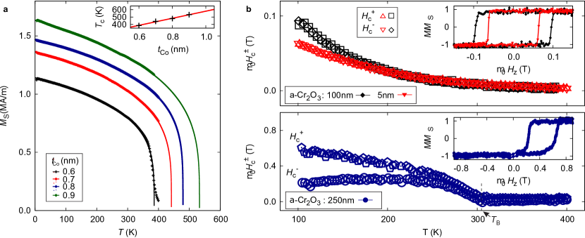
During cool-down from 400 K to 100 K the coercive fields of three samples with different Cr2O3 seed layers were tracked in VSM by constantly sweeping the field. Fig. S2b shows that left and right switching field branches are symmetric in the whole temperature range not only for the sample with 5 nm thick amorphous a-Cr2O3 but also in the case of the much larger thickness of 100 nm. This clearly proves the absence of anti-ferromagnetic properties in the a-Cr2O3 layers that otherwise would induce an exchange bias (EB) effect.
In contrast, the EB effect is very obvious in the reference sample with crystalline -Cr2O3. The hysteresis loop is shifted up to 400 mT below the blocking temperature of about 305 K.
The absence of magnetoelectric properties in a-Cr2O3 layers down to temperatures of 100 K confirms the former finding that a strong perpendicular magnetic anisotropy (PMA) induced by Cr2O3 does not originate from the perpendicular exchange coupling effect at crystalline -Cr2O3/FM interface [49].
The usage of amorphous chromium oxide (a-Cr2O3) for spin-orbit effect studies has hitherto been neglected, due to its possible magneto-electric properties and related effects. The strong PMA induced by Cr2O3 allows the variation of the FM thickness in a reasonably large range. The aim is to preserve perpendicularly magnetized films from the same sandwiched system over a significant large range. Thus, the possibility to adjust the magnetic properties is provided and the influence of the interfaces can be studied.
S2 Field-driven DW creep motion
The nucleation field distribution is very sharp at small and broadens for larger thicknesses accompanied by an increase of nucleation sites. For similar Pt/Co/Pt systems an asymmetric nucleation for opposite initial magnetization saturation states at defects has been reported [50], which might stem from the recently discussed step-edge-induced DMI [51].
In a certain field range, that is different for each sample, DW motion is observed such that it does not develop overhanging wall sections. For larger this field range starts to overlap with the nucleation field distribution, so that in at higher fields it can not be discerned, whether a sample area remagnetized due to nucleation or wall propagation.
The field-driven DW propagation is classified into different propagation regimes [52, 53]. With successively increasing external magnetic field the creep, thermally assisted flux flow and depinning regimes are observed until the flow motion regime is asymptotically reached. While the highly non-linear response at low fields is well understood in terms of the creep law, the regimes close to the depinning are both experimentally and theoretically less clear according to Ref. [53].
Also the typical field ranges of the flow regime are hard to realize in experiment as they have to be applied as well-defined short-time large-amplitude field pulses. For these two reasons the following investigations are performed in the creep regime.
Under small magnetic fields applied along the easy axis of magnetization, the DW velocities obey the creep law [54, 52]
| (S3) |
with the value of the critical exponent exactly . The two creep law parameters and can be deduced from the linear fit in the representation of the data (Fig. S3b).
The parameters and are functions of the pinning properties of the sample [54] determined by the correlation length and the pinning strength of the disorder
| (S4) |
with the attempt frequency , pinning barrier and critical field .
A systematic behavior of the scaling parameters as function of the cobalt thickness is obtained that is similar to other intrinsic magnetic parameters. The thicker and the lower the creep velocity, the more disrupted is the circular shape of the domains. The origin of this DW morphology differences lies in the increasing amount of pinning sites [52].
Both the nucleation field of the investigated pinning site and the creep motion behavior are symmetric under magnetization reversal. The observation of macroscopic DW creep inherently measures an average DW dynamics that neglects local lateral contributions due to film roughness or the granular structure. This average effectively describes an asymmetric film, where only the polar -axis is distinguished with an effective -symmetry. Locally the defects naturally break this polar simple structure and contribute to the transient pinning of the wall. Since the domain shape remains circular, there is no evidence for an effective lower symmetry and additional DMI contributions that break the -symmetry, which allows the description in terms of the theoretical assumption of the symmetry breaking from the -interface.
With an additionally field applied perpendicularly to the easy axis of magnetization, the domain growth exhibits an asymmetric distortion [55] as shown in Fig. S4. This is a consequence of the combined modification of the DW energy by and the DMI field acting in the DW and can be used to deduce the DMI constant from the asymmetry ration of the DW creep velocities of (+) and (-) DWs moving along the axis of as derived in the methods section of the paper.
The Eq. (5) can be solved numerically for .
As shown in Fig. S6 the dimensionless values of left and right side of Eq. (5) are situated on the diagonal for a correctly adjusted .
All points that are deviating from the plot diagonal are not captured by the assumption of the model of sufficiently small (i.e. the factor [31]) and have to be omitted for the analysis.
In most of the previous reports [24, 26, 31, 56] it is assumed, that the minimum occurring in -curves Fig. S4 marks the position where the external field cancels the DMI field. In an approximative approach and only for a limited number of cases can then be directly read from a usually broad minimum. This serves as a direct and fast, but only crude measure of considering the typically observed data sets, as e.g. shown in Fig. S4.
The minimum is usually found in field ranges where the magnetization within the domains is starting to get tilted (i.e. [31]). This alters the DW energy by essentially changing the demagnetization factor of the wall and in turn also its mobility. Hence the minimum position cannot be simply identified with . This becomes increasingly important for thicker films where the anisotropy field is smaller and consequently leads to distortions of the -curves (see Fig. S4).
Furthermore, the DMI field is a function of all micromagnetic parameters including the saturation magnetization , anisotropy energy , exchange parameter and DMI strength . The rescaling to the DMI constant requires a precise knowledge of all these parameters. As is difficult to determine, usually the bulk value (=16 pJ/m for cobalt) is assumed.
In the following it will be discussed, how the assumption of the bulk exchange parameter can distort the results of the DMI field and the DMI strength for the studied //CrOx/Co()/Pt samples series. It has been shown that the true exchange parameter in these films is markedly reduced. When using the bulk in the analysis, the curves of the DMI field and the DMI strength obtained from the minimum approximation and the low field analysis derived in this work are not matching, as shown in Fig. S6. The experimentally obtained significant reduction of corrects the deviation between the differently determined values. The DMI constants calculated from the minimum approximation of with the bulk are clearly overestimated, and are shifted towards the results of the -independent low-field analysis, when the correct exchange parameters are inserted (Fig. S6b). The DMI fields of the low-field analysis are underestimated when considering the bulk and are shifted towards the results of the minimum approximation (Fig. S6a). Despite the -correction the non-matching trends of of both methods indicates the approximative nature of the minimum approach. Within the errorbars only one matching result is obtained for nm.
Recently doubts about the commonly applied quantification methods for the DMI have been raised [31, 57], as the results from the asymmetric magnon dispersion and various quasistatic approaches (Tab. S1) yield widely differing values of . The presented results exemplify one important reason, as the used approaches so far have been unable to determine and the crucial important exchange constant independently.
The here presented alternative low-field analysis of the field-induced DW velocity asymmetry offers a twofold clarification for the ambiguities of previous results. Firstly one has to be aware of the multi-fold field effects on the DW mobility in different field regions, that can be easily avoided in the low-field approximation. And secondly, the relevance of every single micromagnetic parameter for the calculation and rescaling of quantities has to be strictly considered.
It was further proposed to ascribe the asymmetry of the domain expansion in the picture of a dissipation effect attributed to chiral damping [58]. According to this idea the DW velocity is inversely proportional to the damping of the system. Depending on the DW chirality the damping is either enhanced or diminished by , with the exchange length and the DW magnetization component perpendicular to the film normal. In contrast to the previously presented approach the attempt frequency in the creep parameter , Eq. (S4), is modified by the DMI induced chiral damping, while the is only affected by the hard axis field. According to Ref. [58], this results in a entirely different qualitative trend of the -curves. Contrary to the observation in the here studied samples, no shift along the field axis of this curve is predicted in this model. This precludes the interpretation of the data in terms of the chiral damping.
S3 Generation of circular magnetic objects
| (nm) | (m) | (mT) | (mT) | ||
|---|---|---|---|---|---|
| 0.6 | 2.0 0.4 | 0.06 | 2.864 | 3.182 | 0.14 |
| 0.7 | 1.84 0.4 | - | 2.789 | - | |
| 0.8 | 0.84 0.20 | 0.29 | 2.496 | 2.815 | 0.52 |
| 0.9 | 0.59 0.20 | - | 2.347 | - | |
| 1.0 | 0.54 0.10 | 5.42 | 2.285 | 2.603 | 1.10 |
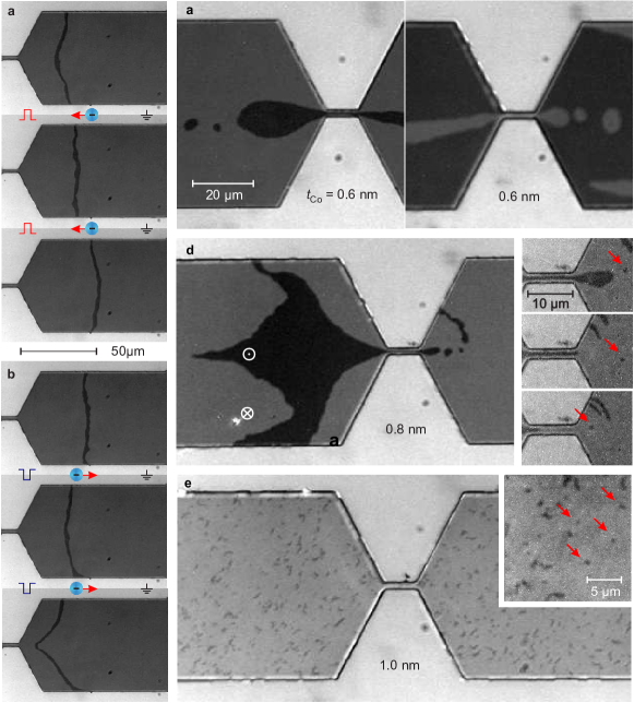
Circular chiral magnetic objects may be generated in the scheme of Jiang et al. [3] or by applying a demagnetization routine. In the prepared microstripes a coherent current-induced motion of two DWs enclosing a domain is observed upon the application of current pulses to the magnetic stripe (see Fig. S8a and b).
The DWs move against the direction of the electron flow, and consequently the DW shift changes sign with the reversal of the current direction. The constriction of the microstripe causes inhomogeneities of the current density which reflects in a distinct DW velocity profile across the microstripe width with a velocity maximum at the center of the stripe (see last image in Fig. S8b).
The current-induced DW motion is attributed to the action of spin-orbit torques[46, 47] on the DWs. It is required that the DWs are homochiral to enable a coherent motion of the object. Additionally, a DW magnetization component parallel to the current direction (i.e. Néel-like type wall) is needed in order to allow for the spin-orbit torques to efficiently induce DW propagation against the direction of electron motion. In the presence of DMI these DW properties are a natural consequence which also result in the formation of winding pairs.
Circular homochiral magnetic objects are generated due to the contraction of a domain channel in divergent currents during the expulsion from the constriction area, when additionally applying an easy axis field () to stabilize the created magnetic object (inset of Fig. S8d). The resulting objects sometimes are of arbitrary shape and usually shrink to circular objects of a typical diameter. Small alternating external magnetic fields can assist to reach this equilibrium state. Due to large pinning in the samples the objects are rather immobile when applying either magnetic field or current pulses.
In the samples with 0.9 nm the strong pinning prevents an efficient current-induced motion. Instead a typical meander pattern of magnetic domains is observed. In these cases the circular objects were observed during the magnetization reversal as remainder of the continuously shrinking meander structures.
Considering the scaling of the characteristic diameter of the circular objects with the cobalt layer thickness one can identify them as magnetic bubble domains or skyrmions. The individual scaling behaviors are discussed in the following assuming a constant exchange parameter for simplicity.
The diameter of bubbles is related to the ratio of the DW energy and the shape anisotropy. In the case of the bubble collapse, this ratio is determined by the stability criterion, which is monotonically increasing with the collapse diameter. The shape anisotropy is a quadratic function of the saturation magnetization, which decreases almost linearly with decreasing in the investigated samples. Therefore decreases with increasing . Hence, cylindrical bubble domains stabilized by the dipolar stray fields are expected to shrink in size with increasing layer thickness, i.e. their size should be inversely proportional to .
On the other hand the skyrmion diameter is approximately proportional to the chiral modulation length ) scaling with the ratio of ferromagnetic to asymmetric exchange constant. For decreasing with increasing an increase of the skyrmion diameter is expected at constant . Chiral skyrmions are therefore expected to become larger in thicker films.
The opposing trends allow to identify the character of the observed circular objects. Quantitative estimates then can corroborated the identification, as bubbles are generally much larger than skyrmions under reasonable assumptions about the materials parameters.
The observed magnetic objects have diameters of the order of 1 m. As shown in Fig. 1 their diameters follow the inversely proportional thickness trend violating the skyrmion diameter scaling . Hence, objects are identified as homochiral bubble domains and the bubble domain theory is employed to determine the remaining unknown magnetic material parameter from the bubble size (Methods). Tab. S8 summarizes the experimental and calculated parameters.
Only if the skyrmion scaling is observed, the exchange parameter can be evaluated in the framework of skyrmion theory. Micromagnetic simulations (Methods) with known , and can be performed to determine the exchange parameter by only varying until the resulting diameter matches the experimentally observed skyrmion size.
In principle a homochiral bubble should be convertible to skyrmion by constriction. Vice versa the expansion of a skyrmion could generate a bubble domain. In the experiments the nucleation of a reverse domain from the collapse site of a bubble domain in opposite field was not observed. This infers that at least one of transformations from homochiral bubbles into skyrmions or vice versa is unlikely to appear in the systems in the chosen experimental condition. Standard Kerr microscopy imaging does not provide the magnification for a visual documentation of this processes given the estimated diameter range for the skyrmions. Together with the hitherto unclarified energetics of the transmutation process between the two objects
this topic remains unsettled.
S4 DMI discussion
A strongly diverging Pt resistivity in the ultra thin limit of Pt films suggest an increase of Pt/Co interface roughness below 5 nm [42]. It has been established from structural characterization methods that heavy metals are showing an increasingly rough growth for increasing layer thicknesses above 10 nm [59]. Furthermore, investigations of the DMI strength in systems with ultra-thin Pt cover layers revealed inhomogeneous coverage below 2 nm [60]. The result of these studies suggests the following scenario for the heavy metal film growth. Below the percolation threshold, estimated to be about 2 nm, heavy metals form porous, non-closed layers. This is indicated by almost non-conducting properties [42], coverage effect in the DMI study of Ref. [60] as well as the finding of this work that samples with Pt cover layers thinner than 2 nm are susceptible to oxidation. The continuing improvement of the Pt conductivity up to 6 nm as found in Ref. [42] suggests a smoothening of the layers before the roughness increases again [59].
Recent ab initio calculations, Fig. 2 of Ref. [22] show a complex distribution of DMI contributions in every atomic layer of Pt/Co and Pt/Co/MgO stacks. Considering the calculation results for Pt/Co interfaces, two limits for the DMI are predicted. A maximum DMI of =2.3 pJ/m is given by taking into account the contribution of the single Co layer adjacent to the Pt layer. The lower limit or averaged DMI of =1.5 pJ/m is calculated as the sum over all atomic layer contributions for typical Co layer thicknesses (3 ML). It is further concluded [22] that the presence of the MgO interface results in an average DMI value exceeding of the Pt/Co interface. This is attributed to a contribution of same sign and similar strength arising at the Co/MgO interface promising the ability to enhance the DMI by precise engineering of the FM/MO interface.
Figure S9 contains a summary of data reported so far on HM/FM/MO systems.
The DMI constant and are plotted as a phase diagram [23] to gauge an empirical correlation of the DMI and the details of the sample. A first cluster of comparable Pt/Co/MO samples is formed around an average value of (1.770.27) pJ/m. Systems with intrinsically different aluminum- [28, 29, 30], magnesium- [36, 22] or gadolinium [31] oxides yield fairly comparable DMI values considering the error bars.
Therefore, it is concluded, that the Co/Pt-interface is the dominating factor and no clear evidence for an impact of the type of MO on the DMI strength can be found. This result matches with the expectation of weak hybridization of electronic states between Co and MO. In this light the upper cluster lies perfectly within the DFT predicted limits (blue area in Fig. S9) suggesting a crucial impact of the Co/Pt interface only. Although a FM/MO contribution might be present, it is not strictly needed to explain the results in the upper cluster. Moreover, it would be required that the DMI contribution arising from the Co/MO interface has the same sign and a similar magnitude independent of the MO (such as Al, Mg or Gd oxides) or its oxidation level.
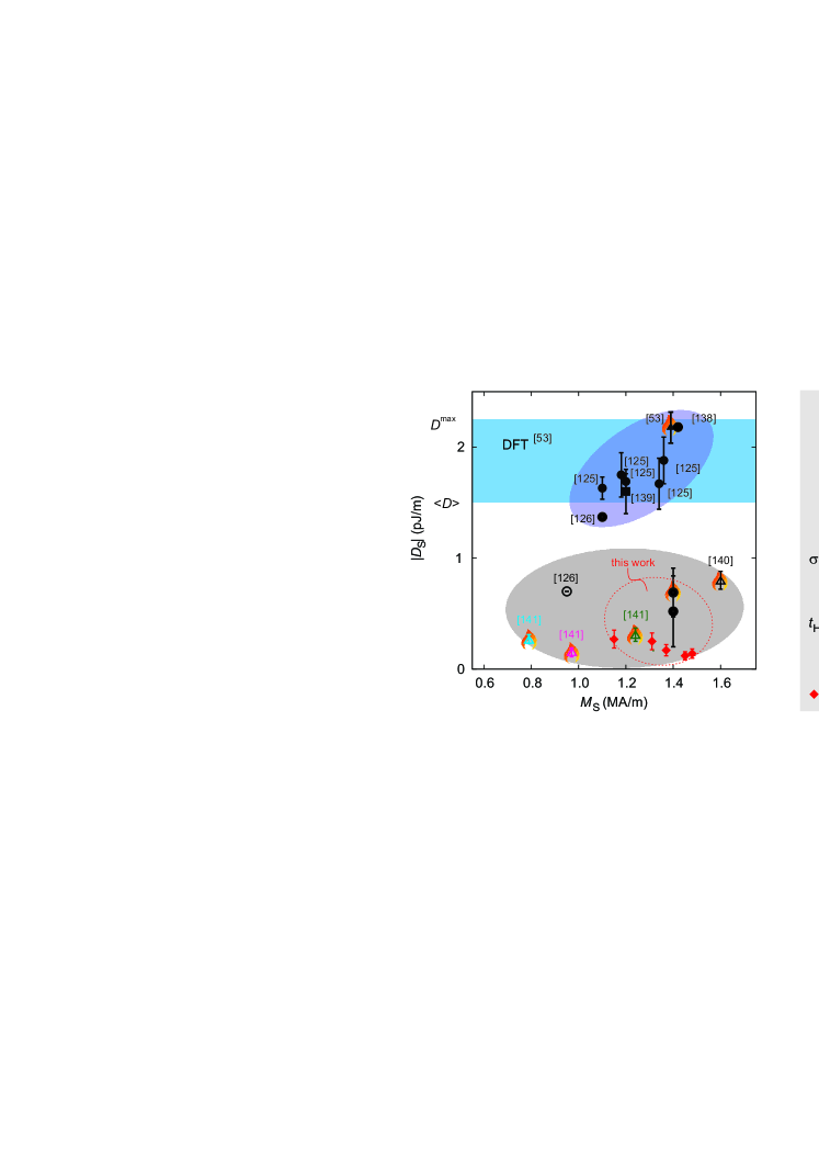
A second cluster is formed at lower DMI values by our results joined by systems comprised of structurally more complex ferromagnets like CoFeB [36, 29] or different heavy metals (HM) such as Ta, TaN, W and Hf [61, 57, 62] in the bottom layer. It has been suggested that the difference in DMI strength for different HMs originate from their respective electro-negativity [61]. This interpretation might be compromised by the mircostructural details of the interfaces, that are expected to vary with the different heavy metals and were disregarded in Ref. [61]. In the clarification of this aspect account should be taken of both for the growth conditions of different HMs and the additional complexity of the employed CoFeB ferromagnetic layer. The latter causes undefined changes of the interface properties due to composition variation and/or boron migration to the interfaces [63]. At the current state, these systems can not be consulted for the evaluation of the possible DMI mechanism.
Nevertheless, assuming a significant contribution of the Co/MO interface the grouping samples with chromium oxide in the lower cluster could then only be explained by an anti-parallel contribution of the CrOx/Co interface partly canceling that of the Co/Pt interface. The obtained experimental results strongly suggest that the DMI in Pt/Co/MO systems dominantly arises from the Pt/Co interfaces, since no empirical evidence for a contribution of the metal-oxide/Co interface to the DMI strength is obtained. The differences of DMI strength between the samples are likely consequences of different interface qualities.
| stack | ||||||
|---|---|---|---|---|---|---|
| (MA/m) | (MA/m) | (pJ/m) | (pJ/m) | |||
| //Ta(4)/Pt(4)/Co(t)/AlOx(2) | 1.42 | [30] | ||||
| //Ta(3)/Pt(3)/Co(t)/MgO | 1.40 | 27.5 | 1.5h, 250∘C, vac. | [22] | ||
| //Ta(3)/Pt(3)/Co(0.6)/AlOx(2) | 1.36 | 0.79 | [28] | |||
| //Ta(3)/Pt(3)/Co(0.8)/AlOx(2) | 1.18 | 0.67 | [28] | |||
| //Ta(3)/Pt(3)/Co(0.9)/AlOx(2) | 1.20 | 0.57 | [28] | |||
| //Ta(3)/Pt(3)/Co(0.95)/AlOx(2) | 1.34 | 0.35 | [28] | |||
| //Ta(3)/Pt(3)/Co(1.2)/AlOx(2) | 1.10 | 0.08 | [28] | |||
| //Pt(5)/Co(1)/GdOx(t) | 1.20 | 0.56 | 16 | 35s O2-plasma | [31] | |
| //Pt(4)/Co(t)/AlOx(2) | 1.10 | [29] | ||||
| //Pt(2)/CoFeB(0.8)/MgO(2) | 1.60 | 0.19 | 1h, 240∘C, vac. | [36] | ||
| //Pt(4)/CoFeB(t)/AlOx(2) | 0.95 | [29] | ||||
| //TaN(1)/CoFeB(1)/MgO(2) | 1.24 | 1h, 300∘C, vac. | [57] | |||
| //W(3)/CoFeB(1)/MgO(2) | 0.79 | 1h, 300∘C, vac. | [57] | |||
| //Hf(1)/CoFeB(1)/MgO(2) | 0.97 | 1h, 300∘C, vac. | [57] |
Sputtered finely polycrystalline thin magnetic films will have various contributions to the chiral DMI, which may compete and eventually average to a vanishing twisting effect, in particular if different surfaces of rotated grains or surface defects like steps cause alternating twisting effects on the magnetization.
A random distribution of local DMI terms along the surface with alternating signs and directions of Dzyaloshinskii-vectors in the microscopic local DMI between local spins may average to a very weak effective chiral coupling.
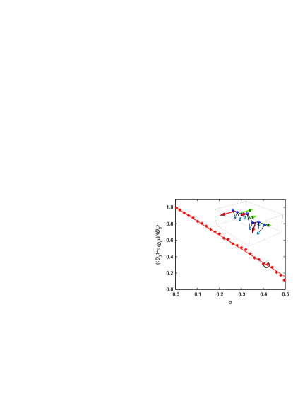
To provide a cartoon picture of the possible averaging mechanism, the roughness influence on the DMI strength is evaluated by a modified Levy-Fert three-site model [64]. To calculate the dependence of the DMI strength on the degree of disorder, the disorder/roughness has been introduced as a Gaussian distribution of the interatomic distances around an ideal lattice constant with standard deviation [65]
| (S5) |
, are the distance vectors from the impurity to corresponding FM sites, the distance vector between FM sites, while is corresponding DMI vector.
Based on the obtained calculation results the average of the -component of is found to be constant for all while the standard deviation of this component linearly increases. It is concluded, that the effective DMI constant , which is relevant e.g. for the altered DW motion in the experiments, is related to the reduced average of the -component by its standard deviation . This results in an almost complete destruction of the DMI at larger disorder as one can see qualitatively from Fig. S10. Even though a constant average should result in the maintenance of chiral order, the large local deviations diminish the effective DMI.
The inset in Fig. S10 shows the distribution of DM vectors in a linear chain of atoms with disorder. Only nearest neighboring magnetic atoms (blue/dark gray spheres) have been considered in the calculations. Each pair has been coupled via a nearest neighboring heavy metal atom (cyan/light gray spheres). For the sake of comparison three left atomic bonds are completely ordered in a hcp-like manner.