Valley filtering in spatial maps of coupling between silicon donors and quantum dots
Abstract
Exchange coupling is a key ingredient for spin-based quantum technologies since it can be used to entangle spin qubits and create logical spin qubits. However, the influence of the electronic valley degree of freedom in silicon on exchange interactions is presently the subject of important open questions. Here we investigate the influence of valleys on exchange in a coupled donor/quantum dot system, a basic building block of recently proposed schemes for robust quantum information processing. Using a scanning tunneling microscope tip to position the quantum dot with sub-nm precision, we find a near monotonic exchange characteristic where lattice-aperiodic modulations associated with valley degrees of freedom comprise less than 2 % of exchange. From this we conclude that intravalley tunneling processes that preserve the donor’s and valley index are filtered out of the interaction with the valley quantum dot, and that the and intervalley processes where the electron valley index changes are weak. Complemented by tight-binding calculations of exchange versus donor depth, the demonstrated electrostatic tunability of donor/QD exchange can be used to compensate the remaining intravalley oscillations to realise uniform interactions in an array of highly coherent donor spins.
Following proposals for spin-based quantum computingKane (1998); Loss and DiVincenzo (1998), spin qubits have been demonstrated in, e.g., diamondChildress et al. (2006), GaAsPetta et al. (2005); Nowack et al. (2011); Shulman et al. (2012); Medford et al. (2013), Si donorsPla et al. (2012) and Si quantum dots (QDs)Maune et al. (2012); Kim et al. (2014); Veldhorst et al. (2015); Reed et al. (2016). Exchange coupling plays a key role in these proposalsKane (1998); Loss and DiVincenzo (1998) and has been employed experimentally to couple spins over short distancesNowack et al. (2011); Veldhorst et al. (2015), and to define multi-spin qubitsPetta et al. (2005); Maune et al. (2012); Shulman et al. (2012); Medford et al. (2013); Kim et al. (2014); Reed et al. (2016) that can be coupled over larger distances via electric interactionsShulman et al. (2012), as also expected for spin-orbit qubitsFlindt et al. (2006); Nowack et al. (2007); Nadj-Perge et al. (2010); Salfi et al. (2016a, b). Because of the importance of exchange interactions, the impact of silicon’s valley degrees freedom on electron tunneling and exchange has been the subject of many theoretical studiesCullis and Marko (1970); Koiller et al. (2001, 2002); Wellard and Hollenberg (2005); Testolin et al. (2007); Hill (2007); Pica et al. (2014); Gamble et al. (2015); Wang et al. (2016); Nielsen et al. (2012); Zimmerman et al. (2017). Notably, small changes in donor positionCullis and Marko (1970); Koiller et al. (2001, 2002); Wellard and Hollenberg (2005); Pica et al. (2014); Gamble et al. (2015); Wang et al. (2016) and QD surface roughnessNielsen et al. (2012); Zimmerman et al. (2017) are expected to produce large modulations of exchange coupling, affecting two-qubit gate fidelities, owing to the lattice-aperiodicity of the valley wavevector. For donors, the negative effects of the predicted rapid non-monotonic dependence of exchange could be be reduced by atomic precision placementFuechsle et al. (2012); Weber et al. (2014) and/or quantum control schemes to recover two-qubit gate infidelitiesTestolin et al. (2007); Hill (2007). While predictions of the amplitude of the non-monotonic oscillations vary significantlyCullis and Marko (1970); Koiller et al. (2001, 2002); Wellard and Hollenberg (2005); Testolin et al. (2007); Hill (2007); Pica et al. (2014); Gamble et al. (2015); Wang et al. (2016); Nielsen et al. (2012); Zimmerman et al. (2017), experimentally establishing the strength of the exchange modulations has proven a difficult task and experimentally probing the role valleys in exchange has received no direct attention.
Tunneling and exchange in coupled donor/QD systemsLansbergen et al. (2008); Foote et al. (2015); Urdampilleta et al. (2015); Harvey-Collard et al. (2017) underpin some recent theory proposals for robust spin-based quantum computingSrinivasa et al. (2015); Pica et al. (2016); Tosi et al. (2017) seeking to exploit the long donor spin coherence timesTyryshkin et al. (2011); Steger et al. (2012); Wolfowicz et al. (2013) without direct exchange between donors. The role of valleys in coupled donor/QD systems differs compared to the more well studied case of two donorsDehollain et al. (2014); Gonzalez-Zalba et al. (2014); Weber et al. (2014): the absence of and valleys in the two-valley () QD state means that intravalley exchange processes, where electrons preserve their valley index, occur for the valleys but not for and valleys of the donor. Though not yet observed experimentally, this filtering of and valley degrees of freedom from intravalley donor/QD exchange should eliminate the main source rapid non-monotonic variations of exchange with in-plane donor position. However, weaker intervalley processes where electrons change their valley indexNing and Sah (1971); Pantelides and Sah (1974) remain a potential source of rapid non-monotonic exchange variations. Ignored in exchange calculations to dateCullis and Marko (1970); Koiller et al. (2001, 2002); Wellard and Hollenberg (2005); Testolin et al. (2007); Hill (2007); Pica et al. (2014); Gamble et al. (2015), intervalley processes become stronger as wavefunctions gets smallerNing and Sah (1971); Pantelides and Sah (1974). Large variations in exchange are also expected with donor depth variations, due to intravalley tunneling, where the phase of the donor (QD) electron is pinned by the ion (interface). The extent to which these processes influence schemes for donor/QD based quantum computing has yet to be establishedSrinivasa et al. (2015); Pica et al. (2016); Tosi et al. (2017).
Here we experimentally investigate whether changes in lateral QD position can overcome variations of donor/QD exchange associated with high spatial frequency “valley” oscillations and slow envelope function decay, for three dimensional donor positioning uncertainty. This is accomplished by experimentally probing the exchange coupling of a donor bound electron with a highly localized electrostatic QD whose lateral position relative to the donor can be controlled with sub-nm precision. The single-electron QD, which has a large meV charging energy and correspondingly few-nm small spatial extent, is formed beneath a passivated Si surface and its position, and coupling to donors, is controlled by moving the tip laterally above the sample surface. Here, we measure the donor/QD energy spectrum by single-electron transportSalfi et al. (2014); Voisin et al. (2015) to quantify the strength of the intervalley interference processes in the exchange coupling . We note that the tunability of the exchange interaction opens up interesting possibilities to electrically probe small-scale dopant-based quantum simulatorsSalfi et al. (2016c); Le et al. (2017); Dusko et al. (2018), or to perform electrical spin readout on optically active impurity centers in materials like silicon carbideKoehl et al. (2011); Castelletto et al. (2013), siliconBuckley et al. (2017); Beaufils et al. (2018), and diamondBrenneis et al. (2015); Bourgeois et al. (2015).
We find that lattice-aperiodic exchange has a small amplitude of the nominal exchange coupling, evidencing the valley filtering effect and setting an upper bound on the intervalley tunneling strength. We also experimentally explore the tunability of the donor/QD exchange with , and find that a modest nm lateral QD shift changes the donor/QD exchange by an order of magnitude. Finally, we show that the QD also has a negligible impact on the electronic orbital and valley population of the donor, which is nm beneath the Si surface, which is important for some proposalsSrinivasa et al. (2015); Pica et al. (2016). Using sp3d5s∗ calculations, we find that the observed tunability of donor/QD exchange can readily compensate variations in exchange due to nm scale donor depth uncertainty. These results show that valley-induced variations in donor/QD exchange can be (i) altogether neglected for in-plane donor positioning variations due to the valley filtering effect and weak intervalley scattering, and (ii) compensated for donor depth variations by modest electrostatic tuning of QD wavefunctions using surface gatesSrinivasa et al. (2015); Pica et al. (2016); Tosi et al. (2017), without distorting the donor wavefunction.
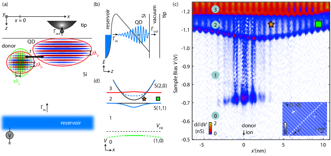
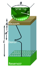
The key ingredient in our experiment is a single-electron QD whose coupling to individual donors can be tuned by controlling the QD position with sub-nm precision, using a scanning tunnelling microscope (STM) tip (Fig. 1a). The QD state is formed below a silicon/vacuum surface when the bands are locally bent downwards by the tip due to a bias applied to a reservoir (Fig. 1b)Morgenstern et al. (2001); Freitag et al. (2016). The QD and donor are contained in a lightly doped region, above a highly doped reservoir and below a (100) hydrogen terminated surface (Fig. 1a). The doping gradient was prepared by thermal annealingSalfi et al. (2014).
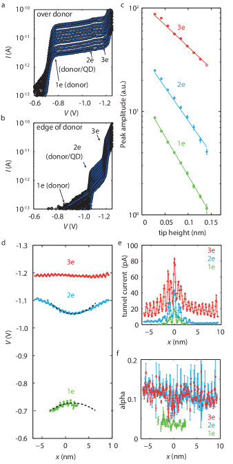
The energy of the QD was probed by spatially resolved single-electron tunneling. For the data shown in the map of Fig. 1c containing a neutral donor resonanceSalfi et al. (2014); Sinthiptharakoon et al. (2014) at V, we identify the first electron in a tip-induced QD state when the bands are bent downward for the resonance at V, away from the donor. Notably, the resonance shifts to V as the QD approaches the neutral donor showing that the coupled donor/QD state has a lower energy than the isolated donor and QD, since less downward bias of the localized state (relative to the reservoir) is required for resonant tunneling.
The observed local dip of the QD resonance near a neutral donor in Fig. 1c is inconsistent with a non-interacting state of the donor and QD where the QD energy would not depend on tip position (Fig. 1d, lower black line). To explain the data we need to consider spin singlet paired two-electron states S with electrons on the donor and on the QD. Charging an isolated donor with a second electron can also be ruled out, since a parabolic S(2,0) resonance would be expected in this case (Fig. 1d, upper black line). This is because as the tip moves away from the donor it is less effective at locally influencing the potential at the donor siteTeichmann et al. (2008) so a larger bias is needed to overcome the donor’s on-site Coulomb repulsion. In contrast, the resonance in Fig. 1c flattens out, approaching S(1,1)-like behaviour. Consequently the two-electron (2e) state in Fig. 1c can only be understood as a hybridized superposition of S(1,1) and S(2,0) singlets (Fig. 1d, solid blue).
Importantly, the donor/QD system forms a molecular state in Fig. 1c since the donor/QD exchange energy well exceeds the reservoir tunnel rates, . This result is obtained by combining two experimentally established inequalities: First has a lineshape of a thermally broadened reservoir (Fig. 2a), so . Second, well exceeds , as will be shown later.
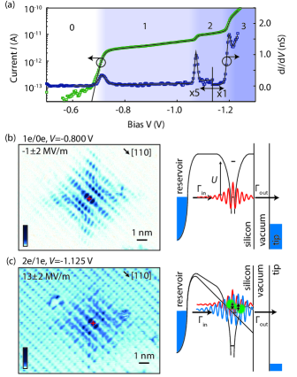
Using the spatially resolved map of tunneling from the donor at V (Fig. 2b) we identify the donor ground stateMiwa et al. (2013); Sinthiptharakoon et al. (2014) by the A1 valley interference patternSalfi et al. (2014). We determine the donor depth beneath the silicon surface ( nm) using a comprehensive tunnelling image analysisUsman et al. (2016). We assume zero electric field for comparison with Fig. 2b, which is justified since the tip bias V induces a small electric field MV/mSMr . With the donor/QD state in the bias window at V, the electric field in the sample is considerably larger (, see SMr, ). With the second resonance in the bias window, spatially resolved electron tunnelling to the tip (Fig. 2c) represents a quasi-particle wavefunction (QPWF)Rontani and Molinari (2005); Salfi et al. (2016c); Maruccio et al. (2007); Schulz et al. (2015).
For the discussion of the measured two electron donor/QD hybrid QPWF resonance in Fig. 2c we use the spin singlet model illustrated in Fig. 1d with , where is the probability amplitude for . For the transition, the tunneling current is SMr . Here is the donor orbital for electron number , is the movable QD’s position relative to the donor, is the lattice-scale structure of the moving QD’s wavefunction, and is a differential operator that takes the STM tip orbital into accountChen (1990). We have found exceptionally good agreement of our single donor measurementsSalfi et al. (2014); Voisin et al. (2015) with sp3d5s∗ theory, including -orbital tipsUsman et al. (2016).
As expected, the centre of the donor/QD QPWF map (Fig. 2c) strongly resembles the measured neutral donor (Fig. 2b) because both S and S contain donor bound orbitals, as reflected in the above expression for . We note that when the transition is in the bias window, the transition also remains energetically allowed (Fig. 2c). However, following the transition, the transition is much less likely than a transition because the electron loading rate from the reservoir far exceeds the tunnel rate to the tip SMr . Hence, the strong appearance of the donor in the QD resonance of Fig. 2c is not due to a transition. Rather, it confirms the pairing interaction of the QD with the donor.
Away from the donor, the donor/QD resonance (Fig. 2c) is lattice periodic in the plane as expected for a QD wavefunction containing only and valleysAndo (1982); Boykin et al. (2004). Importantly, the QD and donor states are expected to have a significant vertical overlap as illustrated in Fig 1a, since the QD charge density is expected to peak at , just nm from the donor ion at . Here, was estimated using the triangular well approximationAndo (1982) with , where MV/m is the electric field and is the longitudinal electron effective mass in SiSMr .
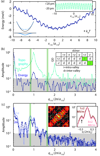
The remainder of the analysis focuses on the dependence of the envelope and spatial oscillations present in the donor/QD resonance energy . Plotted in Fig. 3a, obtained from Fig. 1c and the extracted lever armSMr , varies by meV over a nm range of tip positions. Notably, the interface experienced by the QD is atomically flat (Fig. 1c, inset), which is important since roughness disturbs the valley phase and exchange coupling of QDsGoswami et al. (2006); Nielsen et al. (2012); Yang et al. (2013); Zimmerman et al. (2017); Boross et al. (2016); Ferdous et al. (2018); Huang et al. (2017). The donor/QD energy map is dominated by exchange coupling , which in turn contains tunneling and exchange terms and Koiller et al. (2001). Here, is an effective charging energy, is the donor charging energy and is the QD/donor electron repulsion. The remaining contribution to is the Coulomb interaction of the QD with the neutral donor, estimated to be meVSMr . Importantly, the Fourier decomposition of (Fig. 3b) contains no lattice-aperiodic components above % of the average of (at ). Given that comprises more than 50 % of and the residual Coulomb interactions in do not have lattice aperiodic components, the 1% upper bound for corresponds to a 2 % upper bound of lattice aperiodic components of .
Tunneling and exchange in a coupled donor/QD system differs from two donorsCullis and Marko (1970); Koiller et al. (2001); Wellard and Hollenberg (2005); Pica et al. (2014); Gamble et al. (2015); Wang et al. (2016) because the QD is a superposition of valleys only, and the donor is a six-valley superposition as evidenced by lattice-aperiodic components in the Fourier transforms of STM tunnel current maps (Fig. 3c). Notably, the six-valley superposition of the deep donor is hardly affected at all by the QD electrostatic potential, even at an applied electric field of MV/m below the 2e resonance ( V). This is evidenced by the Fourier decomposition of the donor measurements below the 2e resonance (Fig. 3c, left inset). The amplitude of the Fourier peak at (black arrow in the right inset of Fig. 3c) reflects the and valley populationSalfi et al. (2014); Saraiva et al. (2016), and depends very little on the tip bias in our experiment (Fig. 3c). By extending our theory comparisonUsman et al. (2016) to include electric fields, we estimate a 0.5 % change in the population of the and valleys with the increase in electric field from MV/m to MV/m due to the STM tip voltageSMr . This is important because for shallower donors where ion-implant statistical uncertainty are suppressedvan Donkelaar et al. (2015), hybrid donor/QD systems can be formed with negligible perturbation to donor valley composition and hyperfine coupling.
We note that contains a lattice periodic oscillation (Fig. 3a, and Fig. 3b). This oscillation is likely an artefact from QD energy and wavefunction changes induced by tip-height variation (Fig. 3a, inset). For the former, an energy shift of ) is expectedVoisin et al. (2015), where is the lever arm from our fit. For pm (Fig. 3a, inset) meV, in agreement with the measured meV oscillation. Notably, the smooth exchange variation in Fig. 3a indicates that the valley phaseZimmerman et al. (2017); Boross et al. (2016); Ferdous et al. (2018) varies little, even though the electric field varies by MV/m due to the change in the resonance voltage from V to V.
We now consider lattice-aperiodic oscillations due to interference of valley degrees of freedom in coupled donor/QD systems. The spectral decomposition of can be theoretically understood from an extended Hubbard model for donor/QD tunneling, , and exchange, . Here, is the donor/QD separation, is the donor (QD) potential, () is the six valley donor (two-valley QD) wavefunction. In , intravalley (valley preserving) and intervalley (valley modifying) terms have lattice-aperiodic prefactors , since values are distributed about the conduction band minima. While the intravalley tunneling present in inter-donor exchange can be evaluated readilyKoiller et al. (2001), it is expected to be absent here for and valleys since they are not present in the QD state. The remaining intervalley processes where electrons change valley index while tunnelingNing and Sah (1971); Pantelides and Sah (1974) contribute lattice-aperiodic terms to . Hence, the bound on the lattice aperiodic exchange reflects both the effectiveness of valley filtering and provides an upper bound on the strength of intervalley exchange compared to total exchange, which to our knowledge, has not been reported to date. In particular, the intervalley exchange falls outside the scope of the effective mass approximation, but is expected to be enhanced for localized states compared to extended states. This is relevant because of the nm-spatial extent of the localized wavefunctions measured here, which is similar to silicon’s lattice constant nmLuttinger and Kohn (1955).
The experimentally confirmed weakness of the intervalley tunneling means that lateral and vertical donor positioning uncertainty of donors will influence donor/QD exchange in different ways. Lateral donor positioning uncertainty will influence coupling predominantly through the nm scale envelope decay length of the QD. In contrast, vertical donor positioning uncertainty will influence coupling through a combination of the vertical decay length of the donor and QD and interference processes in the intravalley exchange. The interference should contain an oscillatory term in donor depth because the surface pins the valleys of the QD, while the ion pins the valleys of donor bound electron. The strategy that stands out to compensate these exchange variations is to adjust the QD confinement potential and therefore overlap of the QD state with the fixed donor. This is already accomplished in our experiment since the QD follows the potential of the STM tip, and in proposed devices could be realized by tuning surface gate voltagesPica et al. (2016); Tosi et al. (2017). In particular, our measurements (Fig. 3a) show that a change of donor/QD separation by nm changes donor/QD exchange by an order of magnitude, showing that strongly confined QDs allow for a tremendous exchange tuning range.
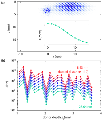
To determine if this tuning range is sufficient to overcome intravalley oscillations in exchange due to depth variations in the donors, a quantitative theory analysis has been carried out with atomistic sp3d5s∗ tight binding. Experimentally measuring these oscillations is difficult since it would require to ability to change the valley phase of the QD wavefunction, or directly measuring meV values of exchange with direct transport, which is not possible in our scheme at . The QD state in the calculation was calibrated so that full configuration interaction (FCI) wavefunctionsWang et al. (2016); Tankasala et al. (2018) reproduce experimentally measured spectra. A nm STM tip radius was found to reproduce the bias where and QD transitions occur, away from the donor. The lowering of the addition energy due to donor/QD coupling when the QD is directly over the donor is calculated to be meV, compared to the value meV in experiments (Fig. 3a).
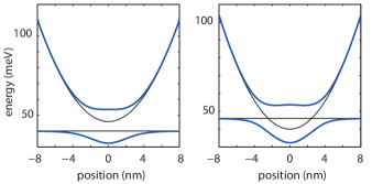
The expected variation in exchange with vertical donor positioning uncertainty was estimated by computing the donor/QD exchange for a range of donor depths and QD distances. The geometry used in the calculation includes the tip potential and donor ion potential. A cross section of the calculated charge density including the donor () and QD () is shown in Fig. 4a. In agreement with our measurements, the exchange varies slowly with lateral QD position (Fig. 4a, Inset), showing that tight binding accurately reproduces the weak intervalley scattering observed in experiments. The calculated exchange varies rapidly with donor depth (Fig. 4b), but notably, the total variation including the rapidly varying intravalley interference and envelope decay is less than two orders of magnitude for depths between and nm. This is important because it indicates that variations in exchange due to donor depth uncertainty can be compensated by adjusting donor/QD wavefunction overlap using gates. The calculations for different donor/QD lateral displacements along the 110 direction (Fig. 4b) show that a change of QD position of nm, between 18.43 nm and 23.04 nm, is sufficient to overcome this variation. We also note that similar to inter-donor exchange, residual coupling uncertainty can in principle be corrected by quantum controlTestolin et al. (2007); Hill (2007).
In conclusion, we have spatially mapped the energy of a neutral donor coupled to a single-electron QD that can be positioned in the plane with sub-nm accuracy using an STM tip. Besides additional applications of coupling to optically active impuritiesKoehl et al. (2011); Castelletto et al. (2013); Brenneis et al. (2015); Bourgeois et al. (2015); Buckley et al. (2017); Beaufils et al. (2018) or small-scale quantum simulatorsSalfi et al. (2016c); Le et al. (2017); Dusko et al. (2018), our results highlight that, similar to predictions for donor/donor interactions in strained Si, donor/QD interactions Srinivasa et al. (2015); Pica et al. (2016); Tosi et al. (2017); Harvey-Collard et al. (2017) do not suffer from valley-induced variations in exchange due to in-plane donor positioning uncertainty. The demonstrated monotonic tunability of donor/QD exchange with QD position is therefore promising for the realisation of uniform exchange couplings between highly coherent donors using tunable, electrostatically defined QDsSrinivasa et al. (2015); Pica et al. (2016); Tosi et al. (2017), that are compatible with an all donor based approachKane (1998); Hill et al. (2015).
Acknowledgements.
The authors would like to thank D. Culcer for helpful discussions. We acknowledge support from the ARC Centre of Excellence for Quantum Computation and Communication Technology (CE110001027), and partial support from the US Army Research Office (W911NF-08-1-0527). JS acknowledges support from an ARC DECRA fellowship (DE160101490). The authors acknowledge the use of computational resources from NanoHUB.org/NCN, and the Pawsey Supercomputing Centre with funding from the Australian Government and the Government of Western Australia. This work used the Extreme Science and Engineering Discovery Environment (XSEDE) ECS150001, which is supported by National Science Foundation grant number ACI-1548562Towns et al. (2014).Supplemental Material
.1 Electric field experienced by donor and QD
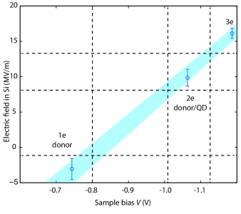
In this section we experimentally extract the vertical component of the tip-induced electric field, which eventually confines a single electron against the vacuum interface of Si in the undoped layer of the sample. It has been modelled using a simple one-dimensional electrostatic description accounting for the dependence of the single-electron tunneling peak voltage on tip height . In this approach, the electric field in the vacuum is given by , which is reduced by silicon’s relative dielectric constant giving Salfi et al. (2014); Voisin et al. (2015). Electric fields extracted using this procedure are plotted against bias in Fig. 5. Three different peak voltages from Fig. 1c in the main text were tracked: the donor 1e resonance (), the donor/QD 2e resonance (), and the 3e resonance ().
.2 Donor depth and repopulation of valleys due to electric fields in neutral donor state
In this section we perform and theory/experiment comparison showing that the electric field of the tip has a small impact on the valley population one-electron ground state of the donor. As a baseline, we start with wavefunction measurements in the smallest electric field (Fig. 5, V, MV/m), and where single dopants can be pinpointed with lattice precision in three dimensionsUsman et al. (2016). We re-plot the Fourier representation of the tunnel current along a direction for , for the deep donor discussed throughout the main text ( nm) shown in Fig. 6a in the main text. Plotted alongside this data is the same quantity for an applied electric field MV/m at a sample bias V, the same data is shown in Fig. 1c of the main text. Here, the ratio of the side peak at and the main peak at , given in Table 1, is proportional to product of and valley populationSalfi et al. (2014).
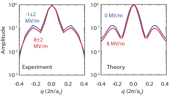
The Fourier decomposition of the predicted STM image for this depth is shown in Fig. 6b, for a uniform electric field MV/m and 8 MV/m, showing a good agreement with experiment with the tip-induced potential. A detailed analysis of the valley population of the donor, carried out on the tight-binding wavefunction using a basis change with the Slater orbitals described elsewhereSalfi et al. (2014), reveals only a 1% change in valley population for the higher field. Based on the good theory/experiment match and the valley repopulation estimate for the theory donor, we estimate the change in valley population of the measured donor, due to the tip-induced potential that confines the quantum dot (QD), is only around %.
| Electric Field | Expmt/Theory | 0 MV/m | 8 MV/m |
|---|---|---|---|
| Side-lobe ratio | Expmt. | 0.13 | 0.10 |
| Side-lobe ratio | Theory | 0.13 | 0.09 |
| Valley population (%) | Theory | 32.8 | 32.3 |
| Valley population (%) | Theory | 34.5 | 35.4 |
.3 Single-electron tunneling
In the following analysis we show how to extract addition energies for the 1e, 2e, and 3e transitions. We also show that in the limit , the presence of the charge transition in the bias window blocks the tunneling from contributing to the total current. We employ a classical rate equation analysis of electron tunneling to describe single-electron transport through multiple charge levels in our donor/QD systemBonet et al. (2002) with thermally broadened reservoirs. The starting point for this model is in ref. Voisin et al., 2015. Here, this model is generalized to non-zero temperature and multiple charge states. Within this framework, the total current is given by
| (1) |
Here, is the probability of electron occupation. Moreover, is the tunnel rate from (to) the tip causing a charge transition on the donor/QD system, which is given by the product of a bare tunnel rate and a Fermi-Dirac statistical distribution for the tip, as follows:
| (2) | ||||
| (3) |
where is the lever-arm for the charge state with bias , is Boltzmann’s constant, K is the sample temperature, and is the addition energy of the -electron state. Note that in our experiment, the reservoir chemical potential is well below the states being probed, relative to temperature, so that electron tunneling from the tip to the bound state is negligible.
We use a master equation to solve for given in ref. Bonet et al., 2002, which also contains tunneling in and out of the reservoir in the sample, to the quantized states. Noting that the current depends exponentially on tip height, (Fig. 7a,b), we can conclude that to the tip is much less than the from the reservoir. To zeroth order in , our rate equation model yields
| (5) |
where is the probability of an electron in the sample reservoir at the energy for the charge state.
We fit the measured -dependent spectrum in Fig. 7a,b. We employ an exponential barrier lowering with bias described by in . Fits for the tunnel current in the centre of the donor, and a few nm away from the donor, are shown for different tip heights as blue lines superimposed on the data in Fig. 7a and Fig. 7b, and are in excellent agreement with the data. The extracted values for as a function of tip height are shown in Fig. 7c, and demonstrate the exponential tip height dependence of current from experiments, as expected. The solution to the rate equations in the limit of small given in Equation 5 establishes the result that when the charge transition enters the bias window, the tunnel current reflects only this transition, and blocks the transition from contributing to the total tunneling current. Finally, the extracted energy for the two-electron state is given in Fig. 3a in the main text.
We fit the -dependent spectral data in the main text, Fig. 1c to obtain the voltage , lever arm and tunnel rate in this model, and extract the energy using and spatially smoothed values of , as plotted in Fig. 3a. The fit of the peak voltage, current, and lever arms are shown Fig. 7d, e and f. Notably for the peak voltage, close to the donor, the parabolic dependence on tip voltage is centred along the same coordinate nm. This offset from the donor center probably reflects the difference in the location of the centre of mass of the QD wavefunction, and the atom position where tunneling to the tip occurs.
.4 Simplified Hubbard model for spectrum and images
In this section we theoretically discuss a Hubbard model for the energy spectrum and images that is motivated by features observed in the experiments. Here, the donor-QD system is described by potentials of the donor and of the QD. Defining two single-electron Hamiltonians and , where is the kinetic energy operator, the states of interest in the separated systems corresponding to the donor and QD are and respectively, which satisfy equations and respectively. Then in the composite system defined by the total applied potential , the one-electron problem is determined by the Hamiltonian , and the two-electron problem is determined by the Hamiltonian where is a function of coordinate only, is a function of coordinate only, and is the electron-electron Coulomb repulsion.
To solve the one and two-electron problems we construct a Wannier basis of maximally localized orbitalsSchliemann et al. (2001), and , where is the overlap. The value ensures the orthogonality of the Wannier orbitals, i.e., , while the normalization is ensured by the prefactor .
.4.1 One-electron spectrum
For the one-electron Hamiltonian in the Wannier basis , the eigenstates obey
| (6) |
where is the identity matrix, is the donor/QD detuning, is the tunneling from to due to the total potential of the donor and tip, and energies and reflect confinement by and due to the donor and tip. The eigenenergies are:
| (7) |
.4.2 Two-electron spectrum
We expand the two-electron problem in a basis of singlets and triplets of the QD and donor Wannier functions written above. The singlets and triplets are
| (8) | |||
| (9) | |||
| (10) | |||
| (11) | |||
| (12) | |||
| (13) |
where , , , and .
We evaluate all the matrix elements of in the above basis. The singlet and triplet subspaces separate due to their spin orthogonality. The singlet subspace is described by
| (14) |
where is an effective charging energy to put two electrons on the donor, is an effective charging energy to put two electrons on the QD, is the charging energy of the donor level, is the mutual Coulomb repulsion of the QD and donor, is the charging energy of the QD level, and is an exchange interaction. The simplest limit is to diagonalize the upper block assuming that double occupation of the QD is unlikely (), giving
| (15) |
while the triplet energy is given straightforwardly by .
.4.3 Donor/QD resonance transition energy
When the single-electron donor/QD detuning is much larger than the two-electron effective charging energy, as expected for our experiments, we obtain a transition energy
| (16) |
From the definitions of and we obtain
| (17) |
where is the energy of the non-interacting QD’s ground state, and the final two terms are the Coulombic interaction of the QD with the neutral donor. Finally we rewrite the transition energy as
| (18) |
The purely Coulombic interaction of the neutral donor and the QD was calculated using
| (19) |
where we have assumed the donor is at the origin. Evaluating this integral using a Monte Carlo technique we find that varies in space and peaks at meV for when the QD overlaps the donor strongest. The small value of this interaction is attributed to the fact that the donor is neutral. Then, the transition energy should be dominated by exchange terms
| (20) |
accounting for most of the meV spatial variation in energy for Fig. 3a in the main text.
.4.4 transition image
The donor/QD system forms a molecule weakly probed by single-electron tunneling by the reservoirsSalfi et al. (2016c), such that the STM image represents a quasi-particle wavefunctionRontani and Molinari (2005). For our two-electron state and transition, the quasiparticle wavefunction is
| (21) |
for a single-electron final state . Then the total current is the sum of currents for each possible final state, given by , where is a derivative operator accounting for the orbital content of the STM tipChen (1990). The tip orbital with d-like symmetry has been found to be important to describe real space STM images of donor-bound electrons in siliconUsman et al. (2016). Considering two possible final states, the one-electron donor state and the one-electron QD state, we obtain
| (22) | ||||
Since the QD follows the tip, we note that only the lattice-periodic component of the QD wavefunction can be detected, so we must replace with . Doing this we obtain the expression for presented in the main text.
.5 Full configuration interaction model
A full configuration interaction approach using tight-binding wavefunctions, used in ref. Tankasala et al., 2018 to model two-electron states of donors in uniform electric fields, was used to model the interactions of the donor and tip-induced QD. Here, the uniform electric field is replaced by a non-uniform potential of an STM tip, as necessary for the STM tip to induce a QD as observed. We describe a procedure for calibrating parameters for the tip-induced potential shown schematically in Fig. 9, and give some details on how the results quoted in the main text are obtained. Note that the depth is fixed by single-donor metrology, for measurements taken near the flat-band conditionUsman et al. (2016).
First, we performed electrostatic calculations of the STM/vacuum/silicon junction using finite element analysis. Then we obtain the single electron energies and wavefunctions of the dot or hybrid donor-dot using atomistic the tight-binding technique including the electrostatic potential. The simulations were done in NEMO3DRahman et al. (2009). Then using the single electron wavefunctions, a basis of two-electron Slater Determinants is constructed and full configuration interaction calculations are performed taking into account the image charges, as described in ref. Tankasala et al., 2018. Diagonalizing the FCI Hamiltonian, the computed 2e total energies, charging energies and singlet-triplet splittings were obtained.
The STM tip parameters were fixed by comparing the binding energy and charging energy of the QD state when it is far away from the donor, at the boundaries of Fig. 1c in the main text. In our experiment, relative to the flat-band voltage ( V, Fig. 5), a sample bias V (actual bias V) and V (actual bias V) are required to bring the state into resonance with the sample reservoir. We could reproduce these binding and charging transitions using a tip radius of nm, for an expected reservoir depth of nm, a tip opening angle assumed to be ∘ and tip height nm. Variations in the tip opening angle and tip height were found to have less of an influence than the tip radius and reservoir depth. Reproducing the binding and charging transition voltages gives us confidence that the Bohr radius of the tip-induced QD is similar to the actual value in experiments.
For these tip and reservoir parameters, we estimated the modulation of the two-electron energy when the single-electron QD interacts with the single electron of the neutral donor at the depth determined from our experiments. In our transport experiment this is equivalent to comparing the transition energy of the QD state in the absence of interactions with the donor (the QD binding energy), to the transition energy of the QD/donor state, when the tip-induced dot is directly above the donor.
For a donor at we obtain = 53.3 meV - 46.5 meV = 6.8 meV, which is very similar to the value 5.5 meV from experiments. Assuming a donor one unit cell closer to the surface at gives = 56.7 meV - 46.5 meV = 10.2 meV, a larger interaction. This is because a donor closer to the surface has a larger overlap, and therefore exchange interaction, with the QD.
merlin.mbs apsrev4-1.bst 2010-07-25 4.21a (PWD, AO, DPC) hacked Control: key (0) Control: author (0) dotless jnrlst Control: editor formatted (1) identically to author Control: production of article title (0) allowed Control: page (1) range Control: year (0) verbatim Control: production of eprint (0) enabled
References
- Kane (1998) B E Kane, “A silicon-based nuclear spin quantum computer,” Nature 393, 133–137 (1998).
- Loss and DiVincenzo (1998) Daniel Loss and David P DiVincenzo, “Quantum computation with quantum dots,” Phys. Rev. A 57, 120–126 (1998).
- Childress et al. (2006) L Childress, M V Gurudev Dutt, Taylor J MM, A S Zibrov, F Jelezko, J Wrachtrup, P R Hemmer, and M D Lukin, “Coherent Dynamics of Coupled Electron and Nuclear Spin Qubits in Diamond,” Science 314, 281–285 (2006).
- Petta et al. (2005) J R Petta, A C Johnson, J M Taylor, E A Laird, A Yacoby, M D Lukin, C M Marcus, M P Hanson, and A C Gossard, “Coherent Manipulation of Coupled Electron Spins in Semiconductor Quantum Dots,” Science 309, 2180–2184 (2005).
- Nowack et al. (2011) K C Nowack, M Shafiei, M Laforest, G E D K Prawiroatmodjo, L R Schreiber, C Reichl, W Wegscheider, and L M K Vandersypen, “Single-Shot Correlations and Two-Qubit Gate of Solid-State Spins,” Science 333, 1269–1272 (2011).
- Shulman et al. (2012) M D Shulman, O E Dial, S P Harvey, H Bluhm, V Umansky, and A Yacoby, “Demonstration of Entanglement of Electrostatically Coupled Singlet-Triplet Qubits,” Science 336, 202–205 (2012).
- Medford et al. (2013) J Medford, J Beil, J M Taylor, S D Bartlett, A C Doherty, E I Rashba, D P DiVincenzo, H Lu, A C Gossard, and C M Marcus, “Self-consistent measurement and state tomography of an exchange-only spin qubit,” Nature Nanotech 8, 654–659 (2013).
- Pla et al. (2012) Jarryd J Pla, Kuan Y Tan, Juan P Dehollain, Wee H Lim, John J L Morton, David N Jamieson, Andrew S Dzurak, and Andrea Morello, “A single-atom electron spin qubit in silicon,” Nature 489, 541–545 (2012).
- Maune et al. (2012) B M Maune, M G Borselli, B Huang, T D Ladd, P W Deelman, K S Holabird, A A Kiselev, I Alvarado-Rodriguez, R S Ross, A E Schmitz, M Sokolich, C A Watson, M F Gyure, and A T Hunter, “Coherent singlet-triplet oscillations in a silicon-based double quantum dot,” Nature 481, 344–347 (2012).
- Kim et al. (2014) Dohun Kim, Zhan Shi, C B Simmons, D R Ward, J R Prance, Teck Seng Koh, John King Gamble, D E Savage, M. G. Lagally, Mark Friesen, S N Coppersmith, and Mark A Eriksson, “Quantum control and process tomography of a semiconductor quantum dot hybrid qubit,” Nature 511, 70–74 (2014).
- Veldhorst et al. (2015) M Veldhorst, C H Yang, J C C Hwang, W Huang, J P Dehollain, J T Muhonen, S Simmons, A Laucht, F E Hudson, K M Itoh, A Morello, and A S Dzurak, “A two-qubit logic gate in silicon,” Nature 526, 410–414 (2015).
- Reed et al. (2016) M D Reed, B M Maune, R W Andrews, M G Borselli, K Eng, M P Jura, A A Kiselev, T D Ladd, S T Merkel, I Milosavljevic, E J Pritchett, M T Rakher, R S Ross, A E Schmitz, A Smith, J A Wright, M F Gyure, and A T Hunter, “Reduced Sensitivity to Charge Noise in Semiconductor Spin Qubits via Symmetric Operation,” Phys. Rev. Lett. 116, 110402 (2016).
- Flindt et al. (2006) Christian Flindt, Anders S Sørensen, and Karsten Flensberg, “Spin-Orbit Mediated Control of Spin Qubits,” Phys. Rev. Lett. 97, 240501 (2006).
- Nowack et al. (2007) K C Nowack, F H L Koppens, Yu V Nazarov, and L M K Vandersypen, “Coherent Control of a Single Electron Spin with Electric Fields,” Science 318, 1430–1433 (2007).
- Nadj-Perge et al. (2010) S Nadj-Perge, S M Frolov, E P A M Bakkers, and L P Kouwenhoven, “Spin–orbit qubit in a semiconductor nanowire,” Nature 468, 1084–1087 (2010).
- Salfi et al. (2016a) J Salfi, J A Mol, Dimitrie Culcer, and S Rogge, “Charge-Insensitive Single-Atom Spin-Orbit Qubit in Silicon,” Phys. Rev. Lett. 116, 246801 (2016a).
- Salfi et al. (2016b) J Salfi, Mengyang Tong, S Rogge, and Dimitrie Culcer, “Quantum computing with acceptor spins in silicon,” Nanotechnology 27, 244001 (2016b).
- Cullis and Marko (1970) P R Cullis and J R Marko, “Determination of the Donor Pair Exchange Energy in Phosphorus-Doped Silicon,” Phys. Rev. B 1, 632–637 (1970).
- Koiller et al. (2001) Belita Koiller, Xuedong Hu, and S Das Sarma, “Exchange in Silicon-Based Quantum Computer Architecture,” Phys. Rev. Lett. 88, 027903 (2001).
- Koiller et al. (2002) Belita Koiller, Xuedong Hu, and S Das Sarma, “Strain effects on silicon donor exchange: Quantum computer architecture considerations,” Phys. Rev. B 66, 115201 (2002).
- Wellard and Hollenberg (2005) C Wellard and L Hollenberg, “Donor electron wave functions for phosphorus in silicon: Beyond effective-mass theory,” Phys. Rev. B 72, 085202 (2005).
- Testolin et al. (2007) M J Testolin, C D Hill, C J Wellard, and L C L Hollenberg, “Robust controlled-NOT gate in the presence of large fabrication-induced variations of the exchange interaction strength,” Phys. Rev. A 76, 012302 (2007).
- Hill (2007) Charles D Hill, “Robust Controlled-NOT Gates from Almost Any Interaction,” Phys. Rev. Lett. 98, 180501 (2007).
- Pica et al. (2014) G Pica, B W Lovett, R N Bhatt, and S A Lyon, “Exchange coupling between silicon donors: The crucial role of the central cell and mass anisotropy,” Phys. Rev. B 89, 235306 (2014).
- Gamble et al. (2015) John King Gamble, N Tobias Jacobson, Erik Nielsen, Andrew D Baczewski, Jonathan E Moussa, Inès Montaño, and Richard P Muller, “Multivalley effective mass theory simulation of donors in silicon,” Phys. Rev. B 91, 235318 (2015).
- Wang et al. (2016) Yu Wang, Archana Tankasala, Lloyd C. L. Hollenberg, Gerhard Klimeck, Michelle Y Simmons, and Rajib Rahman, “Highly tunable exchange in donor qubits in silicon,” npj Quantum Inf. 2, 16008 (2016).
- Nielsen et al. (2012) Erik Nielsen, Rajib Rahman, and Richard P Muller, “A many-electron tight binding method for the analysis of quantum dot systems,” Journal of Applied Physics 112, 114304 (2012).
- Zimmerman et al. (2017) Neil M Zimmerman, Peihao Huang, and Dimitrie Culcer, “Valley Phase and Voltage Control of Coherent Manipulation in Si Quantum Dots,” Nano Lett. 17, 4461–4465 (2017).
- Fuechsle et al. (2012) Martin Fuechsle, Jill A Miwa, Suddhasatta Mahapatra, Hoon Ryu, Sunhee Lee, Oliver Warschkow, Lloyd C. L. Hollenberg, Gerhard Klimeck, and Michelle Y Simmons, “A single-atom transistor,” Nature Nanotech 7, 242–246 (2012).
- Weber et al. (2014) Bent Weber, Y H Matthias Tan, Suddhasatta Mahapatra, Thomas F Watson, Hoon Ryu, Rajib Rahman, Lloyd C. L. Hollenberg, Gerhard Klimeck, and Michelle Y Simmons, “Spin blockade and exchange in Coulomb-confined silicon double quantum dots,” Nature Nanotech 9, 430–435 (2014).
- Lansbergen et al. (2008) G. P. Lansbergen, R Rahman, C J Wellard, I Woo, J Caro, N Collaert, S Biesemans, G Klimeck, L C L Hollenberg, and S Rogge, “Gate-induced quantum-confinement transition of a single dopant atom in a silicon FinFET,” Nature Physics 4, 656–661 (2008).
- Foote et al. (2015) Ryan H Foote, Daniel R Ward, J R Prance, John King Gamble, Erik Nielsen, Brandur Thorgrimsson, D E Savage, A L Saraiva, Mark Friesen, S N Coppersmith, and M A Eriksson, “Transport through an impurity tunnel coupled to a Si/SiGe quantum dot,” Appl. Phys. Lett. 107, 103112 (2015).
- Urdampilleta et al. (2015) Matias Urdampilleta, Anasua Chatterjee, Cheuk Chi Lo, Takashi Kobayashi, John Mansir, Sylvain Barraud, Andreas C Betz, S Rogge, M Fernando Gonzalez-Zalba, and John J L Morton, “Charge Dynamics and Spin Blockade in a Hybrid Double Quantum Dot in Silicon,” Phys. Rev. X 5, 031024 (2015).
- Harvey-Collard et al. (2017) Patrick Harvey-Collard, N Tobias Jacobson, Martin Rudolph, Jason Dominguez, Gregory A Ten Eyck, Joel R Wendt, Tammy Pluym, John King Gamble, Michael P Lilly, Michel Pioro-Ladrière, and Malcolm S Carroll, “Coherent coupling between a quantum dot and a donor in silicon,” Nat Comms 8, 1029 (2017).
- Srinivasa et al. (2015) V Srinivasa, H Xu, and J M Taylor, “Tunable Spin-Qubit Coupling Mediated by a Multielectron Quantum Dot,” Phys. Rev. Lett. 114, 226803 (2015).
- Pica et al. (2016) G Pica, B W Lovett, R N Bhatt, T Schenkel, and S A Lyon, “Surface code architecture for donors and dots in silicon with imprecise and nonuniform qubit couplings,” Phys. Rev. B 93, 035306 (2016).
- Tosi et al. (2017) Guilherme Tosi, Fahd A Mohiyaddin, Vivien Schmitt, Stefanie Tenberg, Rajib Rahman, Gerhard Klimeck, and Andrea Morello, “Silicon quantum processor with robust long-distance qubit couplings,” Nat Comms 8, 450 (2017).
- Tyryshkin et al. (2011) Alexei M Tyryshkin, Shinichi Tojo, John J L Morton, Helge Riemann, Nikolai V Abrosimov, Peter Becker, Hans-Joachim Pohl, Thomas Schenkel, Michael L W Thewalt, Kohei M Itoh, and S A Lyon, “Electron spin coherence exceeding seconds in high-purity silicon,” Nature Materials 11, 143–147 (2011).
- Steger et al. (2012) M Steger, K Saeedi, M L W Thewalt, J J L Morton, H Riemann, N V Abrosimov, P Becker, and H J Pohl, “Quantum Information Storage for over 180 s Using Donor Spins in a 28Si ”Semiconductor Vacuum”,” Science 336, 1280–1283 (2012).
- Wolfowicz et al. (2013) Gary Wolfowicz, Alexei M Tyryshkin, Richard E George, Helge Riemann, Nikolai V Abrosimov, Peter Becker, Hans-Joachim Pohl, Mike L W Thewalt, Stephen A Lyon, and John J L Morton, “Atomic clock transitions in silicon-based spin qubits,” Nature Nanotech , – (2013).
- Dehollain et al. (2014) Juan P Dehollain, Juha T Muhonen, Kuan Y Tan, André Saraiva, David N Jamieson, Andrew S Dzurak, and Andrea Morello, “Single-Shot Readout and Relaxation of Singlet and Triplet States in Exchange-Coupled P31 Electron Spins in Silicon,” Phys. Rev. Lett. 112, 236801 (2014).
- Gonzalez-Zalba et al. (2014) M F Gonzalez-Zalba, André Saraiva, Maria J Calderón, Dominik Heiss, Belita Koiller, and Andrew J Ferguson, “An Exchange-Coupled Donor Molecule in Silicon,” Nano Lett. 14, 5672–5676 (2014).
- Ning and Sah (1971) T H Ning and C T Sah, “Multivalley Effective-Mass Approximation for Donor States in Silicon. I. Shallow-Level Group-V Impurities,” Phys. Rev. B 4, 3468–3481 (1971).
- Pantelides and Sah (1974) Sokrates T Pantelides and C T Sah, “Theory of localized states in semiconductors. I. New results using an old method,” Phys. Rev. B 10, 621–637 (1974).
- Saraiva et al. (2016) A L Saraiva, J Salfi, J Bocquel, B Voisin, S Rogge, Rodrigo B Capaz, M. J. Calderón, and Belita Koiller, “Donor wave functions in Si gauged by STM images,” Phys. Rev. B 93, 045303 (2016).
- Salfi et al. (2014) J Salfi, J A Mol, R Rahman, G Klimeck, M Y Simmons, L C L Hollenberg, and S Rogge, “Spatially resolving valley quantum interference of a donor in silicon,” Nature Materials 13, 605–610 (2014).
- Voisin et al. (2015) B Voisin, J Salfi, J Bocquel, R Rahman, and S Rogge, “Spatially resolved resonant tunneling on single atoms in silicon,” J. Phys.: Condens. Matter 27, 154203 (2015).
- Salfi et al. (2016c) J Salfi, J A Mol, R Rahman, G Klimeck, M Y Simmons, L C L Hollenberg, and S Rogge, “Quantum simulation of the Hubbard model with dopant atoms in silicon,” Nat Comms 7, 11342 (2016c).
- Le et al. (2017) Nguyen H Le, Andrew J Fisher, and Eran Ginossar, “Extended Hubbard model for mesoscopic transport in donor arrays in silicon,” Phys. Rev. B 96, 245406 (2017).
- Dusko et al. (2018) Amintor Dusko, Alain Delgado, André Saraiva, and Belita Koiller, “Adequacy of Si:P chains as Fermi–Hubbard simulators,” npj Quantum Inf. 4, 1 (2018).
- Koehl et al. (2011) William F Koehl, Bob B Buckley, F Joseph Heremans, Greg Calusine, and David D Awschalom, “Room temperature coherent control of defect spin qubits in silicon carbide,” Nature 479, 84–87 (2011).
- Castelletto et al. (2013) S Castelletto, B C Johnson, V Ivády, N Stavrias, T Umeda, A Gali, and T Ohshima, “A silicon carbide room-temperature single-photon source,” Nature Materials , – (2013).
- Buckley et al. (2017) Sonia Buckley, Jeffrey Chiles, Adam N McCaughan, Galan Moody, Kevin L Silverman, Martin J Stevens, Richard P Mirin, Sae Woo Nam, and Jeffrey M Shainline, “All-silicon light-emitting diodes waveguide-integrated with superconducting single-photon detectors,” Appl. Phys. Lett. 111, 141101 (2017).
- Beaufils et al. (2018) C Beaufils, W Redjem, E Rousseau, V Jacques, A Yu Kuznetsov, C Raynaud, C Voisin, A Benali, T Herzig, S Pezzagna, J Meijer, M Abbarchi, and G Cassabois, “Optical properties of an ensemble of G-centers in silicon,” Phys. Rev. B 97, 035303 (2018).
- Brenneis et al. (2015) Andreas Brenneis, Louis Gaudreau, Max Seifert, Helmut Karl, Martin S Brandt, Hans Huebl, José A Garrido, Frank H L Koppens, and Alexander W Holleitner, “Ultrafast electronic readout of diamond nitrogen-vacancy centres coupled to graphene,” Nature Nanotech 10, 135–139 (2015).
- Bourgeois et al. (2015) E Bourgeois, A Jarmola, P Siyushev, M Gulka, J Hruby, F Jelezko, D Budker, and M Nesladek, “Photoelectric detection of electron spin resonance of nitrogen-vacancy centres in diamond,” Nat Comms 6, 8577 (2015).
- Morgenstern et al. (2001) M Morgenstern, V Gudmundsson, R Dombrowski, Chr Wittneven, and R Wiesendanger, “Nonlocality of the exchange interaction probed by scanning tunneling spectroscopy,” Phys. Rev. B 63, 201301 (2001).
- Freitag et al. (2016) Nils M Freitag, Larisa A Chizhova, Peter Nemes-Incze, Colin R Woods, Roman V Gorbachev, Yang Cao, Andre K Geim, Kostya S Novoselov, Joachim Burgdörfer, Florian Libisch, and Markus Morgenstern, “Electrostatically Confined Monolayer Graphene Quantum Dots with Orbital and Valley Splittings,” Nano Lett. 16, 5798–5805 (2016).
- Sinthiptharakoon et al. (2014) Kitiphat Sinthiptharakoon, Steven R Schofield, Philipp Studer, Veronika Brázdová, Cyrus F Hirjibehedin, David R Bowler, and Neil J Curson, “Investigating individual arsenic dopant atoms in silicon using low-temperature scanning tunnelling microscopy,” J. Phys.: Condens. Matter 26, 012001 (2014).
- Teichmann et al. (2008) K Teichmann, M Wenderoth, S Loth, R Ulbrich, J Garleff, A Wijnheijmer, and P Koenraad, “Controlled Charge Switching on a Single Donor with a Scanning Tunneling Microscope,” Phys. Rev. Lett. 101, 076103 (2008).
- Miwa et al. (2013) J A Miwa, J A Mol, J Salfi, S Rogge, and M Y Simmons, “Transport through a single donor in p-type silicon,” Appl. Phys. Lett. 103, 043106 (2013).
- Usman et al. (2016) M Usman, J Bocquel, J Salfi, B Voisin, A Tankasala, R Rahman, M Y Simmons, S Rogge, and L C L Hollenberg, “Spatial metrology of dopants in silicon with exact lattice site precision,” Nature Nanotech 11, 763–768 (2016).
- (63) See the Supplemental Material which gives details on the measurements, fitting, model expressions for tunneling spectra and images, and numerical calculations.
- Rontani and Molinari (2005) Massimo Rontani and Elisa Molinari, “Imaging quasiparticle wave functions in quantum dots via tunneling spectroscopy,” Phys. Rev. B 71, 233106 (2005).
- Maruccio et al. (2007) Giuseppe Maruccio, Martin Janson, Andreas Schramm, Christian Meyer, Tomohiro Matsui, Christian Heyn, Wolfgang Hansen, Roland Wiesendanger, Massimo Rontani, and Elisa Molinari, “Correlation Effects in Wave Function Mapping of Molecular Beam Epitaxy Grown Quantum Dots,” Nano Lett. 7, 2701–2706 (2007).
- Schulz et al. (2015) Fabian Schulz, Mari Ijäs, Robert Drost, Sampsa K Hämäläinen, Ari Harju, Ari P Seitsonen, and Peter Liljeroth, “Many-body transitions in a single molecule visualized by scanning tunnelling microscopy,” Nature Physics (2015).
- Chen (1990) C Julian Chen, “Tunneling matrix elements in three-dimensional space: The derivative rule and the sum rule,” Phys. Rev. B 42, 8841–8857 (1990).
- Ando (1982) Tsuneya Ando, “Electronic properties of two-dimensional systems,” Rev. Mod. Phys. 54, 437–672 (1982).
- Boykin et al. (2004) Timothy B. Boykin, Gerhard Klimeck, Mark Friesen, S N Coppersmith, Paul von Allmen, Fabiano Oyafuso, and Seungwon Lee, “Valley splitting in low-density quantum-confined heterostructures studied using tight-binding models,” Phys. Rev. B 70, 165325 (2004).
- Goswami et al. (2006) Srijit Goswami, K A Slinker, Mark Friesen, L M McGuire, J L Truitt, Charles Tahan, L J Klein, J O Chu, P M Mooney, D W van der Weide, Robert Joynt, S N Coppersmith, and Mark A Eriksson, “Controllable valley splitting in silicon quantum devices,” Nature Physics 3, 41–45 (2006).
- Yang et al. (2013) C H Yang, A Rossi, R Ruskov, N S Lai, F A Mohiyaddin, S Lee, C Tahan, G Klimeck, A Morello, and A S Dzurak, “Spin-valley lifetimes in a silicon quantum dot with tunable valley splitting,” Nat Comms 4, 1–8 (2013).
- Boross et al. (2016) Péter Boross, Gábor Széchenyi, Dimitrie Culcer, and András Pályi, “Control of valley dynamics in silicon quantum dots in the presence of an interface step,” Phys. Rev. B 94, 035438 (2016).
- Ferdous et al. (2018) Rifat Ferdous, Erika Kawakami, Pasquale Scarlino, Michał P Nowak, D R Ward, D E Savage, M. G. Lagally, S N Coppersmith, Mark Friesen, Mark A Eriksson, Lieven M K Vandersypen, and Rajib Rahman, “Valley dependent anisotropic spin splitting in silicon quantum dots,” npj Quantum Inf. 4, 26 (2018).
- Huang et al. (2017) Wister Huang, Menno Veldhorst, Neil M Zimmerman, Andrew S Dzurak, and Dimitrie Culcer, “Electrically driven spin qubit based on valley mixing,” Phys. Rev. B 95, 075403 (2017).
- van Donkelaar et al. (2015) Jessica van Donkelaar, C Yang, A D C Alves, J C McCallum, C Hougaard, B C Johnson, F E Hudson, A S Dzurak, A Morello, D Spemann, and D N Jamieson, “Single atom devices by ion implantation,” J. Phys.: Condens. Matter 27, 154204 (2015).
- Luttinger and Kohn (1955) J Luttinger and W Kohn, “Motion of Electrons and Holes in Perturbed Periodic Fields,” Phys. Rev. 97, 869–883 (1955).
- Tankasala et al. (2018) Archana Tankasala, Joseph Salfi, Juanita Bocquel, Benoit Voisin, Muhammad Usman, Gerhard Klimeck, Michelle Y Simmons, Lloyd C. L. Hollenberg, S Rogge, and Rajib Rahman, “Two-electron states of a group-V donor in silicon from atomistic full configuration interactions,” Phys. Rev. B 97, 195301 (2018).
- Hill et al. (2015) Charles D Hill, Eldad Peretz, Samuel J Hile, Matthew G House, Martin Fuechsle, S Rogge, Michelle Y Simmons, and Lloyd C. L. Hollenberg, “A surface code quantum computer in silicon,” Science Advances 1, e1500707–e1500707 (2015).
- Towns et al. (2014) J Towns, T Cockerill, M Dahan, I Foster, K Gaither, A Grimshaw, V Hazlewood, S Lathrop, D Lifka, G D Peterson, R Roskies, J R Scott, and N Wilkins-Diehr, “XSEDE: Accelerating Scientific Discovery,” Computing in Science Engineering 16, 62–74 (2014).
- Bonet et al. (2002) Edgar Bonet, Mandar M Deshmukh, and D C Ralph, “Solving rate equations for electron tunneling via discrete quantum states,” Phys. Rev. B 65, 045317 (2002).
- Schliemann et al. (2001) John Schliemann, Daniel Loss, and A MacDonald, “Double-occupancy errors, adiabaticity, and entanglement of spin qubits in quantum dots,” Phys. Rev. B 63, 085311 (2001).
- Rahman et al. (2009) Rajib Rahman, Seung Park, Jared Cole, Andrew Greentree, Richard Muller, Gerhard Klimeck, and Lloyd Hollenberg, “Atomistic simulations of adiabatic coherent electron transport in triple donor systems,” Phys. Rev. B 80, 035302 (2009).