electronic stopping power and threshold effect of channeled slow light ions in HfO2
Abstract
We present study of the electronic stopping power of protons and helium ions in an insulating material, HfO2. The calculations are carried out in channeling conditions with different impact parameters by employing Ehrenfest dynamics and real–time, time–dependent density functional theory. The satisfactory comparison with available experiments demonstrates that this approach provides an accurate description of electronic stopping power. The velocity-proportional stopping power is predicted for protons and helium ions in the low energy region, which conforms the linear response theory. Due to the existence of wide band gap, a threshold effect in extremely low velocity regime below excitation is expected. For protons, the threshold velocity is observable, while it does not appear in helium ions case. This indicates the existence of extra energy loss channels beyond the electron–hole pair excitation when helium ions are moving through the crystal. To analyze it, we checked the charge state of the moving projectiles and an explicit charge exchange behavior between the ions and host atoms is found. The missing threshold effect for helium ions is attributed to the charge transfer, which also contributes to energy loss of the ion.
pacs:
61.85.p,31.15.A,61.80.Az,61.82.MsI INTRODUCTION
Interaction of intruding ion with matter is of continuing interest, the deceleration force involved is mainly characterized by stopping power (SP) Ferrell and Ritchie (1977) or energy deposition per unit distance traveled through the material. This quantity can generally be decomposed into two parts. The first one is the electronic stopping power , which arises from the excitation of the electrons of the target. The second one is the nuclear stopping power due to elastic Coulomb collisions with the nuclei of the target. For particles with velocities below the Fermi velocity of the target, nuclear and electronic stopping are both relevant, and the result of the interaction is a collision cascade Averback and Rubia (1997). Shortly before the particle stops eventually, a global stopping maximum denoted Bragg peak occurs. Thus, studying the energy transferred from slow ions to the target material is at the heart of modern technologies, such as nuclear fission/fusion reactors Odette and Wirth (2005); Horsfield et al. (2016), semiconductor devices for space missions Zeller (1995) and cancer therapy based on ion beam radiation Obolensky et al. (2008); Reeves et al. (2016).
The interest in modeling the SP of ions with velocities between 0.1 and 1 atomic units (a.u. hereafter) has fueled a huge amount of research Cabrera-Trujillo et al. (2003). In this regime the electronic component is generally dominant and the electronic energy loss is predominantly due to interaction with valence electrons Mertens and Winter (2000). The electronic stopping power is a crucial quantity for ion irradiation: it governs the deposited heat, the damage profile, and the implantation depth. Ever since the discovery of , various models and theories have been proposed to calculate depending on the energy regime of the ion. For swift ions, based on the assumption that the atoms of the target are classical oscillator, Bohr Boh (1915, 1913) suggested a formula for the ; employing the first Born approximation, Bethe Bethe (1930) has introduced the first calculations of inelastic and ionization cross section; the Bloch correction Bloch (1933) provides a convenient link between the Bohr and the Bethe scheme. On the other hand, for slow particles, Fermi and Teller Fermi et al. (1947) using electron gas models had reported for various targets; a more general treatment of the applicable to the whole velocity regime was later developed by Lindhard Lindhard (1954) through linear dielectric theory.
Energetic ions penetrate great depth along channels between low–index crystallographic planes, moderating through collisions with electrons, until finally they hit a host atom initiating a cascade of atomic displacements. This phenomenon has been exploited in many important applications such as ion implantation and depth profiling. Glancing collisions with host atoms confine the trajectory of a channelling ion, so most of its energy is lost through electronic excitation. Based on the free electron gas (FEG) model, is predicted to be for 1 atomic units (a.u. henceforth) Fermi et al. (1947). This simple relation has been verified experimentally in many –bonded metals Race et al. (2010); Valdés et al. (1993); Martínez-Tamayo et al. (1996); Pitarke and Campillo (1999).
A different behavior is expected in materials that have a finite minimum excitation energy Tmin, such as noble gas and wide band–gap insulators, given the finite energy required to excite outmost electrons. This finite minimum excitation energy is expected to suppress the energy dispassion due to electron–hole pair excitation at ion energies of several keV Fermi et al. (1947), which results in a threshold effect of SP with respect to the ion velocity Markin et al. (2009). Instead, however, no threshold effect was originally observed in most systems Eder et al. (1997); Peñalba et al. (2001); Møller et al. (2004), with the exception that a threshold velocity of a.u. in LiF under grazing incidence Auth et al. (1998). Recent theoretical and experimental research managed to measure velocities in extremely low velocity regime ( 0.1 a.u) displaying a clear velocity threshold Serkovic et al. (2007); Serkovic Loli et al. (2010); Markin et al. (2009); Ullah et al. (2015); Mao et al. (2014).
In this work, we propose to investigate the behavior of slow ions shooting through a large band–gap insulator HfO2 ( 5.5 eV) and also its threshold effect under channeling condition. For this purpose, we perform non–adiabatic dynamic simulations to mimic the intruding ion as it is propagating through the system by means of time–dependent density–functional theory (TDDFT). The explicit time evolution of the electronic states of the host crystal and the kinetic energy loss of the moving ions are monitored. The key quantity of interest can be extracted from the change of kinetic projectile energy using the thickness of the target.
This article is outlined as follows. In Sec. II, we briefly introduce the theoretical framework and the computational details. Results are presented and discussed in Sec. III, where we concentrate on the analysis of and its threshold effect. In the end, conclusions are drawn in Sec. IV. Henceforth, if no special reservation is made, Hartree atomic units with are used in this paper.
II MODEL AND METHODS
The collision behaviors of intruding ions with the host nuclei and electrons are characterized by the Ehrenfest coupled electron–ion dynamics combined with time–dependent density–functional theory (ED–TDDFT) Zeb et al. (2012); Horsfield et al. (2004); Gross et al. (1996); Calvayrac et al. (2000); Alonso et al. (2008); Page et al. (2008). In this model, electronic degrees of freedom are treated quantum–mechanically within the time–dependent Kohn–Sham (KS) formalism, while the ions are handled classically. This method allows for an excited electronic state ab initio molecular dynamics (AIMD) simulation. The ED–TDDFT can, in general, be defined by the following coupled differential equations:
| (1) | |||||
| (2) |
here and denote the mass and charge of the Ith nuclei, respectively, and describes the corresponding ionic position vector. is the many–body electron wave function in the time domain, for which we define , with , where the coordinates and the spin of the jth electron are implicitly taken into account. Here is the number of electrons of the system.
The electronic Hamiltonian is expressed as , which depends on the instantaneous distribution of the positions of all the nuclei, ( is the number of nuclei of the system), and of all the electrons ; thus, it basically consists of the kinetic energy of electrons, the electron–electron potential and the electron–nuclei potential, which can be formulated as
| (3) | |||||
To solve Eq. (1) for the motion of the nuclei, one has to obtain knowledge of , which typically causes the problem to be intractable. For this reason, we write the force that acts on each nucleus in terms of the electronic density , which is the basic variable of ED-TDDFT (see Ref. Castro et al. (2012) for a detailed description). As a consequence, Eq. (1) can be rewritten as
| (4) | |||||
where the instantaneous density is given by the sum of all individual electronic orbitals, i.e.,
| (5) |
with being occupied KS orbital for the th electron.
Similarly, to obtain explicitly, instead of solving Eq. (2), we make use of the corresponding time–dependent KS equations, which provides an approximation to ,
| (6) | |||||
where is the time–dependent exchange-correlation potential, for which we use the adiabatic local density approximation with Perdew–Wang analytic parametrization Perdew and Wang (1992). The other three terms on the left hand side of Eq. (6) are, in order, the electronic kinetic, the electron–nucleus potential, and the Hartree potential. In this model, the potential energy and forces acting upon the ions are calculated as the simulation proceeds. It should be noted that, in ED–TDDFT, transitions between electronic adiabatic states are included, and the coupling of the adiabatic states with the nuclei trajectories is also considered Andrade et al. (2009). Thus, it allows molecular dynamics simulation for excited electronic states and opens a way to study the electron transfer between the ion and the target electrons during the collision Avendaño-Franco et al. (2012). In the present work, since we are mainly interested in the low velocity regime that is well below the core–electron excitation threshold, only valence electrons of host atoms are considered throughout this work. The coupling of valence electrons to ionic cores is described by using norm–conserving Troullier–Martins (TM) pseudopotentials Troullier and Martins (1991).
In order to investigate electron excitation and electron distribution after the collision, the electron distribution in the conduction band is defined by the projection of the time–dependent wave function to the initial particle states in the conduction band Otobe et al. (2008); Jiao et al. (2013),
| (7) |
where represents the KS orbital index and is the Bloch wave number.
The projectile is initially placed outside the crystal and a TDDFT Yabana and Bertsch (1996); Shukri et al. (2016) calculation was completed to obtain the converged ground state results that are required as the initial condition for subsequent evolution with the moving projectile. Once the convergence of the ground state is achieved, the projectile is then released with the given initial velocity; meanwhile, the KS orbitals are propagated through the time–dependent KS equations by employing the approximated enforced time reversal symmetry method Castro and Marques (2004). The ionic motion is obtained via the numerical solution of Eq. (4) by applying Verlet’s algorithm. Each simulation of the ion–solid collision consists of a well-defined direction of the projectile shooting the HfO2 thin film with experimental density. The calculations were carried out by using the OCTOPUS ab initio code package Marques et al. (2003); Castro et al. (2006). In the present work, the external potential, electronic density, and KS orbitals are discretized in a set of mesh grid points with a uniform spacing of 0.18 Å along the three spatial coordinates in the simulation box. To avoid artificial reflections of the electronic wavefunctions from the boundary, we use a complex absorbing potential boundary Wang et al. (2011) during the collision process.
Physical picture of this study is that: the projectiles are directed along negative z axis with a given velocity. Ionic motion of target atoms is neglected by fixing the host ions in the equilibrium positions because it is supposed to play a marginal role over the total simulation time that is limited to several femtoseconds Correa et al. (2012). was investigated under channeling condition, where the projectiles do not encounter the target nuclei directly. The nuclear contribution to the stopping power, therefore, is negligibly small and can even be completely suppressed when the host atoms are frozen in the equilibrium positions.
Supercell size is chosen so as to reduce the finite size effects while maintaining controllable computational demands. In present work, a FCC structured 222 conventional cell comprising 32 Hf and 64 O atoms is employed, the lattice constants we choose is 5.11 Å, which is identical to the measured value Wyckoff (1963). To ensure the stability of the computation, we use a time step of 0.001 fs. It should be noted that the numerical parameters have been carefully examined, and the chosen parameters are found to be a compromise between the convergence of results and the efficiency of the calculation.
III RESULTS AND DISCUSSION
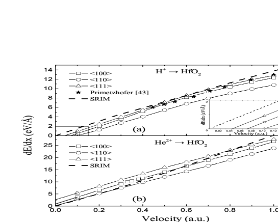
along the middle axes of three different channels is investigated. We show in Fig. 1 the calculated results for of protons and helium ions in HfO2 with velocity range 0.1 – 1.0 a.u., together with the experimental data Primetzhofer (2014). For the sake of comparison, the predictions obtained from the SRIM–2013 data base are also plotted. It should be noted that SRIM results are obtained semi–empirically by averaging over a number of different incident directions with distinct impact parameters; thus, it does not explicitly account for the channeling conditions studied in our calculations. For this reason, the calculated results are expected to follow a qualitative trend of SRIM data, which has been shown in several previous theoretical studies Schleife et al. (2015); Correa et al. (2012); Quashie et al. (2016).
In Fig. 1(a) we find a pronounced agreement between the calculated values and experimental data for of protons along the middle axes of 100 and 111 channels, which shows the power of the TDDFT technique to accurately reproduce electronic stopping power in realistic system. However, in order to obtain the electronic stopping power with high precision, an ensemble average over numerous projectile paths needs to be taken until satisfactory convergence is reached, but this is beyond the scope of this work. As can be seen in Fig. 1, the behavior of protons and helium ions in HfO2 are generally velocity–scaling, which conforms the expected energy dissipation mechanism caused by electron–hole pair excitation. An interesting phenomenon we find in Fig. 1 is that the threshold effect for protons and helium shows a distinctly different trait. Considering the velocity-proportionality assumption, if we extrapolate the calculated data to zero, the threshold velocities for protons shown in Fig. 1(a) are 0.07 a.u., 0.10 a.u., and 0.04 a.u. in the 100, 110, and 111 directions, respectively. For the behavior of helium ions shown in Fig. 1(b), no threshold effect is found.
III.1 Threshold effect in of HfO2
To investigate the different threshold effects between the protons and helium ions, we have explored the possible energy dissipation channels. In the present work, we find is related to charge transfer, which is an additional energy dissipation channel besides electron–hole pair excitation. Many mechanisms may contribute to the charge transfer. Besides the direct transitions such as excitation, ionization, and capture Schiwietz and Grande (2011), the Auger process between the host atoms and ions also plays a pronounced role, in which an electron jumps from the valence band of the host atom to an ion bound state and vice versa. The energy released in such transitions is balanced by an electronic excitation in the medium or on the projectile Muiño (2003). Other possible mechanisms are resonant charge transfer and radiative decay processes of the projectiles. Since pseudopotentials are adopted in the present TDDFT simulation, Auger processes following the inner–shell vacancy can not be considered. Nevertheless, because the kinetic ion energy in the present work is restricted to 25 keV/u and lower, according to the interpretation in Ref. Zhang et al. (2013), direct transition mechanisms are dominant in such a low velocity regime, Auger processes following the inner–shell vacancy make a minor contribution to charge transfer.
Generally, both the neutralization and re-ionization of the ion included in the charge transfer process contribute to the decreasing of ion’s kinetic energy, due to the promotion of electronic states of either the host atoms or the projectile itself. Peńalba Peńalba et al. (1992) reported that charge transfer is an important energy loss channel, especially for projectile around stopping maximum. For protons with 1 a.u. in Aluminum, charge transfer accounts for 15 of total SP. However, it has not been considered in the original SP theory that accounts for linear velocity dependence. The different threshold effect between proton and helium ion in Fig. 1 is studied by checking their charge transfer behaviors in low velocity regime.
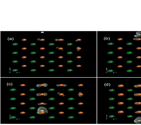
As a first step, the time evolution of a helium ion moving through the 100 channel for a given velocity of 1.0 a.u. is visualized in Fig. 2. Four snapshots covering the entire collision process are presented. Before entering the crystal ( = 0.059 fs), the helium ion projectile is a bare ion [Fig. 2(a)]; when the helium ion is getting close to the crystal ( = 0.095 fs) and penetrating along the channel ( = 0.486 fs), it exchanges charge with the host atoms [Figs. 2(b) and (c)]; after traversing the HfO2 film ( = 0.628 fs); the exiting ion still retains some captured electrons [Fig. 2(d)]. The example in Fig. 2 could be qualitative evidence for the charge transfer during the collisions. The gray region is the change in electron distribution caused by the intruding ion.
The electron density change induced by the helium ion in real time is quantified by integrating the valence charge density within the volume around the projectile ion with a radius of 1.26 Å in the time–dependent calculation, from which the ground state electron density of the target in the corresponding volume has been subtracted and we thus obtained the number of induced electrons in real time. In the present work, we deem this quantity as the charge transferred to the projectiles. A point should be noted is that free electrons caused by electron scattering process may also be included in such approximation, where electrons pile up close to projectile due to the attractive interaction between electrons and the ions Echenique et al. (1981). The choice of 1.26 Å as the integration radius is a compromise between various factors. In this study, we are interested in learning the real–time electron occupying the intruding ion orbitals, and we get it through the discrepancy of density, i.e., the change in electron distribution around the ion between the time–dependent and the ground state calculations. In theory, a larger integration radius can be more effective to fully take a variety of mechanisms and also the highly occupied orbits into account. However, at the same time, it may include more free electrons and excited state electrons of the host atoms that do not belong to the ion and also more excited state electrons caused by the former steps, as shown in Fig. 2.
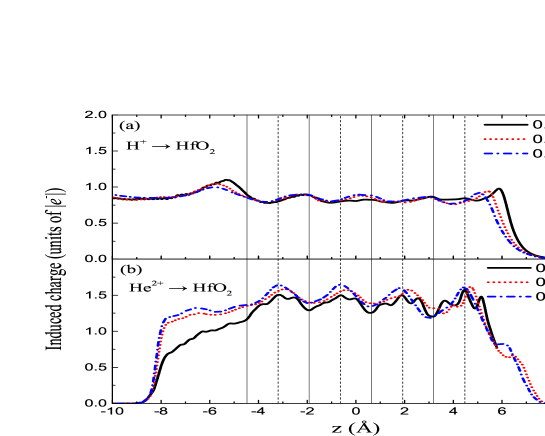
Electrons induced by the H+ and He2+ ions with very low velocities moving along the middle axis of 100 channel are presented in Fig. 3; the periodic variation in induced electron reflects the periodicity of the crystal. As can be seen, the charge exchange between the projectile and host atoms takes place alternately along their trajectories. Generally, protons show less active charge exchange behavior during the collision than helium ions. In the present work, we found charge transfer of protons is sensitive to ions velocity, it becomes less and less obvious as the velocity decreases in the extremely low velocity regime (not shown). While, charge transfer of helium ions shows a weak correlation with velocity. Considering charge transfer accounts for a noticeable share of , in the extremely low velocity regime the contribution to from electron–hole pair excitation becomes feeble and charge transfer may be the dominant energy loss channel. The different threshold effect shown in Fig. 1 can be attributed to the different charge transfer behaviors between two kinds of ions in extremely low velocity regime.
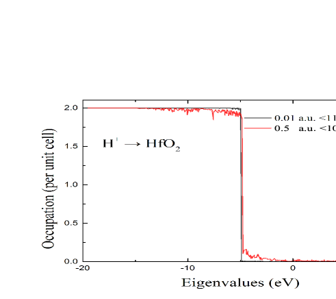
To depict the electron–hole pair excitation, we calculated the electron occupation number distribution in the conduction band for protons at a given velocity of 0.01 a.u. along the middle axis of 110 channel and 0.5 a.u. along the middle axis of 100 channel. Such choices are made with the consideration to compare the cases with and without explicit electron–hole excitation, because 0.01 a.u. in 110 channel is lower than the threshold velocity and 0.5 a.u. in 100 channel is higher than threshold velocity. Results are shown in Fig. 4. The excitation energy of the crystal has been extended to 7 eV in the conduction band by adding empty KS obtials in the simulation. We can see clearly that the excited electrons are distributed broadly in the considered energy range for the proton at velocity of 0.5 a.u. in 100 channel. However, the electrons occupation in conduction band is implicit for the proton at velocity of 0.01 a.u. in 110 channel, and the number of excited electrons in this energy range is much smaller than that of the 0.5 a.u. proton.
As already alluded to in the previous paragraph, electrons excitation from valence band to the conduction band are suppressed by the energy gap. It should be noted that charge transfer discussed above also contributes to electrons excitation. The implicit electrons excitation for 0.01 a.u. proton also demonstrates the missing of charge transfer in very low velocity regime. This means the projectile ion does not lose any energy to the target electron subsystem when the velocities are below a certain threshold, resulting in a threshold effect in the dependence on the velocity. Although the empty KS level does not provide the exact description of the real excited states of the nanostructure, this can be considered as the first approximation to the true excitations of the system Appel et al. (2003); Wasserman and Burke (2005).
III.2 impact parameter dependence of charge transfer and
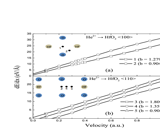
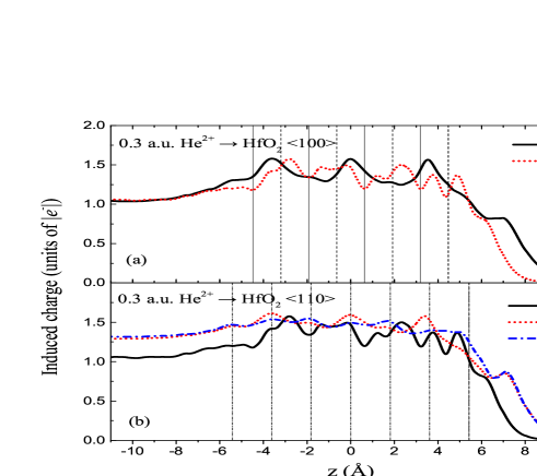
Since the occupied He-1 level is strongly affected by the interaction distance Wang et al. (2001); Wethekam et al. (2008); Monreal et al. (1989); Primetzhofer et al. (2013). So charge transfer behavior may differ for different trajectories. To investigate the effect of impact parameter on charge exchange and threshold velocity, we show in Figs. 5 and 6 the behavior and the corresponding charge transfer profiles versus z coordinates for a given velocity of 0.3 a.u. along two trajectories in 100 channel and three trajectories in 110 channel. The trajectories are chosen to sample different impact parameters within the channel. In the present work, the value of impact parameter is defined as the closest distance to any of Hf atoms along the ion trajectory. The trajectories along the middle axes of the channel have the highest impact parameters and trajectories close to Hf atoms have the lowest impact parameters. For the five trajectories in Fig. 5, the impact parameters are in order 1.279 Å, 0.904 Å, 1.809 Å, 1.357 Å and 0.904 Å.
As can be seen, no threshold effect can be found in 100 channel in both the center and off–center channeling cases shown as trajectories 1 and 2, respectively. While, threshold effect is observed along the trajectories with low impact parameters in the 110 channel, i.e. trajectories 4 and 5, the threshold velocity are 0.05 a.u. and 0.15 a.u., respectively. We notice that the charge transfer behavior shown in Fig. 6 is active for the trajectory in 100 channel with low impact parameter. While, the amplitudes of charge transfer are much smaller along the trajectories in 110 channel with low impact parameters, and trajectory 5 shows a even less evident charge transfer behavior than trajectory 4. This result consist with the threshold effect shown in Fig. 5, which indicates that an active charge transfer may cause vanish of the threshold.
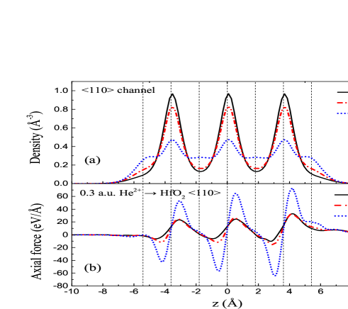
The instantaneous energy loss rate of the projectile ion in a condensed matter system often depends strongly on the specific path taken by the ion and its proximity to atoms and bonds over the course of the trajectory. In the present work, we find is remarkably impact parameter–dependent, results along different trajectories have different magnitudes. To understand the dependence of the on the impact parameter, we show in Fig. 7 the ground state electronic density and the axial force along along three different ion trajectories (shown as black circles in Fig. 5(b)) in 110 channel for helium ions at a given velocity of 0.3 a.u.. The density values are obtained by averaging electron density of cylindrical ion track with a radius of 0.36 Å step by step. The trend of the axial force is similar to that of electron density, and there is a proportional relation between the two to some extent, which is in accordance with the density functional theory (DFT) results Echenique et al. (1986) for FEG. The average density values obtained along the whole trajectories in 100, 110, and 111 channels are 0.35, 0.33, and 0.28 electrons/Å3, respectively, which consists with the amplitude of shown in Fig. 1(b). This suggests that the in channeling conditions is related to the average density along the projectile’s trajectory, corroborating the interpretation in the literatures Wang and Nagy (1997); Wang et al. (1998); Winter et al. (2003); Martingondre et al. (2013); Ullah et al. (2015).
The trend of force also have a direct correlation with the threshold effect. As can be seen, the applied force on helium ion varies like a sine function with respect to the displacement, and trajectories with the low impact parameters have a larger variation. For trajectories 3 and 4, the force is generally above zero, i.e. positive direction, which means the ions are predominantly exposed to drag force along the channel. For trajectory 5, the force exerting on the ion turns up and down periodically (in the axis direction), leading to little net energy loss in the following path, which is consistent with the relatively small threshold velocity of trajectory 5 shown in Fig. 5(b).
It should be noted that, since projectile have distinct charge transfer behaviors along different trajectories, and charge transfer contribute significantly to . So the effect of impact parameter on is also embodied through the charge transfer.
IV CONCLUSIONS
Theoretical study from first principles the electronic stopping power of slow light projectiles in HfO2 has been presented. The velocity–proportional of HfO2 is predicted. A quantitative agreement between the experimental data and our results is achieved. Threshold effect is found when proton is channeled in the HfO2 thin film, while, the expected threshold effect was not found for helium ion channelling the crystal, which was interpreted as a consequence of charge transfer. We have learned that the is sensitive to the impact parameter due to the different electron density experienced by the ions, which is consistent with the assumptions form FEG model. Our results shed light on describing the interaction between the ions and the target electrons without restricting the electrons to the adiabatic surface. To obtain a deeper understanding of the effect of charge transfer on inelastic energy loss, a thorough theoretical analysis of possible charge exchange mechanism in combination with suitable experimental studies is highly desirable.
ACKNOWLEDGEMENTS
One author wants to thank Dr. F. Mao for the fruitful discussions. This work was supported by the National Natural Science Foundation of China under Grant Nos. 11635003, 11025524 and 11161130520, National Basic Research Program of China under Grant No. 2010CB832903, and the European Commissions 7th Framework Programme (FP7-PEOPLE-2010-IRSES) under Grant Agreement Project No. 269131.
References
- Ferrell and Ritchie (1977) T. L. Ferrell and R. H. Ritchie, Phys. Rev. B 16, 115 (1977).
- Averback and Rubia (1997) R. S. Averback and T. D. D. L. Rubia, Solid State Phys 51, 281 (1997).
- Odette and Wirth (2005) G. R. Odette and B. D. Wirth, in Handbook of Materials Modeling: Methods (Springer Netherlands, Dordrecht, 2005) p. 999.
- Horsfield et al. (2016) A. P. Horsfield, A. Lim, W. M. C. Foulkes, and A. A. Correa, Phys. Rev. B 93, 245106 (2016).
- Zeller (1995) H. Zeller, Solid-State Electronics 38, 2041 (1995).
- Obolensky et al. (2008) O. I. Obolensky, E. Surdutovich, I. Pshenichnov, I. Mishustin, A. V. Solov Yov, and W. Greiner, Nucl. Instrum. Methods B 266, 1623 (2008).
- Reeves et al. (2016) K. G. Reeves, Y. Yao, and Y. Kanai, Phys. Rev. B 94, 041108 (2016).
- Cabrera-Trujillo et al. (2003) R. Cabrera-Trujillo, P. Apell, J. Oddershede, and J. Sabin, A I P Conference Proceedings CP680, 86 (2003).
- Mertens and Winter (2000) A. Mertens and H. Winter, Phys. Rev. Lett. 85, 2825 (2000).
- Boh (1915) N. Boh, Philos. Mag. 30, 581 (1915).
- Boh (1913) N. Boh, Philos. Mag. 25, 10 (1913).
- Bethe (1930) H. Bethe, Annalen der Physik 397, 325 (1930).
- Bloch (1933) F. Bloch, Annalen der Physik 408, 285 (1933).
- Fermi et al. (1947) E. Fermi, E. Teller, and V. Weisskopf, Phys. Rev. 72, 399 (1947).
- Lindhard (1954) J. Lindhard, Mat. Fys. Medd. Dan. Vid. Selsk, 28, 41 (1954).
- Race et al. (2010) C. P. Race, D. R. Mason, M. W. Finnis, W. M. C. Foulkes, A. P. Horsfield, and A. P. Sutton, Rep. Prog. Phys. 73, 116501 (2010).
- Valdés et al. (1993) J. E. Valdés, G. A. Tamayo, G. H. Lantschner, J. C. Eckardt, and N. R. Arista, Nucl. Instrum. Methods B 73, 313 (1993).
- Martínez-Tamayo et al. (1996) G. Martínez-Tamayo, J. C. Eckardt, G. H. Lantschner, and N. R. Arista, Phy. Rev. A 54, 3131 (1996).
- Pitarke and Campillo (1999) J. M. Pitarke and I. Campillo, Nucl. Instrum. Methods B 164, 147 (1999).
- Markin et al. (2009) S. N. Markin, D. Primetzhofer, and P. Bauer, Phys. Rev. Lett. 103, 113201 (2009).
- Eder et al. (1997) K. Eder, D. Semrad, P. Bauer, R. Golser, P. Maier-Komor, F. Aumayr, M. Peñalba, A. Arnau, J. M. Ugalde, and P. M. Echenique, Phys. Rev. Lett. 79, 4112 (1997).
- Peñalba et al. (2001) M. Peñalba, J. I. Juaristi, E. Zarate, A. Arnau, and P. Bauer, Phys. Rev. A 64, 012902 (2001).
- Møller et al. (2004) S. P. Møller, A. Csete, T. Ichioka, H. Knudsen, U. I. Uggerhøj, and H. H. Andersen, Phys. Rev. Lett. 93, 042502 (2004).
- Auth et al. (1998) C. Auth, A. Mertens, H. Winter, and A. Borisov, Phys. Rev. Lett. 81, 4831 (1998).
- Serkovic et al. (2007) L. N. Serkovic, E. A. Sánchez, O. Grizzi, J. C. Eckardt, G. H. Lantschner, and N. R. Arista, Phys. Rev. A 76, 040901 (2007).
- Serkovic Loli et al. (2010) L. N. Serkovic Loli, E. A. Sánchez, O. Grizzi, and N. R. Arista, Phys. Rev. A 81, 022902 (2010).
- Ullah et al. (2015) R. Ullah, F. Corsetti, D. Sánchez-Portal, and E. Artacho, Phys. Rev. B 91, 125203 (2015).
- Mao et al. (2014) F. Mao, C. Zhang, J. Dai, and F.-S. Zhang, Phys. Rev. A 89, 022707 (2014).
- Zeb et al. (2012) M. A. Zeb, J. Kohanoff, D. Sánchez-Portal, A. Arnau, J. I. Juaristi, and E. Artacho, Phys. Rev. Lett. 108, 225504 (2012).
- Horsfield et al. (2004) A. P. Horsfield, D. R. Bowler, A. J. Fisher, T. N. Todorov, and M. J. Montgomery, J. Phys. Condens. Matter 16, 3609 (2004).
- Gross et al. (1996) E. K. U. Gross, J. F. Dobson, and M. Petersilka, “Density functional theory of time-dependent phenomena,” in Density Functional Theory II: Relativistic and Time Dependent Extensions, edited by R. F. Nalewajski (Springer Berlin Heidelberg, Berlin, Heidelberg, 1996) pp. 81–172.
- Calvayrac et al. (2000) F. Calvayrac, P. G. Reinhard, E. Suraud, and C. A. Ullrich, Phys. Rep. 337, 493 (2000).
- Alonso et al. (2008) J. L. Alonso, X. Andrade, P. Echenique, F. Falceto, D. Prada-Gracia, and A. Rubio, Phys. Rev. Lett. 101, 096403 (2008).
- Page et al. (2008) J. L. Page, D. R. Mason, and W. M. C. Foulkes, J. Phys. Condens. Matter 20, 611 (2008).
- Castro et al. (2012) A. Castro, M. Isla, J. I. Martínez, and J. Alonso, Chem. Phys. 399, 130 (2012).
- Perdew and Wang (1992) J. P. Perdew and Y. Wang, Phys. Rev. B 45, 13244 (1992).
- Andrade et al. (2009) X. Andrade, A. Castro, D. Zueco, J. L. Alonso, P. Echenique, F. Falceto, and n. Rubio, J. Chem. Theory Comput. 5, 728 (2009).
- Avendaño-Franco et al. (2012) G. Avendaño-Franco, B. Piraux, M. Grüning, and X. Gonze, Theore. Chem. Acc. 131, 1289 (2012).
- Troullier and Martins (1991) N. Troullier and J. L. Martins, Phys. Rev. B 43, 1993 (1991).
- Otobe et al. (2008) T. Otobe, M. Yamagiwa, J.-I. Iwata, K. Yabana, T. Nakatsukasa, and G. F. Bertsch, Phys. Rev. B 77, 165104 (2008).
- Jiao et al. (2013) Y. Jiao, F. Wang, X. Hong, W. Su, Q. Chen, and F. Zhang, Physics Letters A 377, 823 (2013).
- Yabana and Bertsch (1996) K. Yabana and G. F. Bertsch, Phys. Rev. B 54, 4484 (1996).
- Shukri et al. (2016) A. A. Shukri, F. Bruneval, and L. Reining, Phys. Rev. B 93, 035128 (2016).
- Castro and Marques (2004) A. Castro and M. A. L. Marques, Propagators for the Time-Dependent Kohn-Sham Equations (Springer Berlin Heidelberg, 2004) pp. 197–210.
- Marques et al. (2003) M. A. L. Marques, A. Castro, G. F. Bertsch, and A. Rubio, Comput. Phys. Commun. 151, 60 (2003).
- Castro et al. (2006) A. Castro, H. Appel, M. Oliveira, C. A. Rozzi, X. Andrade, F. Lorenzen, M. A. L. Marques, E. K. U. Gross, and A. Rubio, Phys. Status Solidi B 243, 2465 (2006).
- Wang et al. (2011) F. Wang, X. C. Xu, X. H. Hong, J. Wang, and B. C. Gou, Phys. Lett. A 375, 3290 (2011).
- Correa et al. (2012) A. A. Correa, J. Kohanoff, E. Artacho, D. Sánchez-Portal, and A. Caro, Phys. Rev. Lett. 108, 213201 (2012).
- Wyckoff (1963) R. W. G. Wyckoff, Crystal Structures Second edition (Interscience Publishers, 1963) pp. 239–444.
- Primetzhofer (2014) D. Primetzhofer, Nucl. Instrum. Methods B 320, 100 (2014).
- Schleife et al. (2015) A. Schleife, Y. Kanai, and A. A. Correa, Phys. Rev. B 91, 014306 (2015).
- Quashie et al. (2016) E. E. Quashie, B. C. Saha, and A. A. Correa, Phys. Rev. B 94, 155403 (2016).
- Schiwietz and Grande (2011) G. Schiwietz and P. L. Grande, Phys. Rev. A 84, 052703 (2011).
- Muiño (2003) R. D. Muiño, Nucl. Instrum. Methods B 203, 8 (2003), 14th International Workshop on Inelastic Ion-Surface Collisions.
- Zhang et al. (2013) C. L. Zhang, X. H. Hong, F. Wang, Y. Wu, and J. G. Wang, Phys. Rev. A 87, 032711 (2013).
- Peńalba et al. (1992) M. Peńalba, A. Arnau, P. M. Echenique, F. Flores, and R. H. Ritchie, Europhys. Lett. 19, 45 (1992).
- Echenique et al. (1981) P. Echenique, R. Nieminen, and R. Ritchie, Solid State Commun. 37, 779 (1981).
- Appel et al. (2003) H. Appel, E. K. U. Gross, and K. Burke, Phys. Rev. Lett. 90, 043005 (2003).
- Wasserman and Burke (2005) A. Wasserman and K. Burke, Phys. Rev. Lett. 95, 163006 (2005).
- Wang et al. (2001) N. P. Wang, E. A. García, R. Monreal, F. Flores, E. C. Goldberg, H. H. Brongersma, and P. Bauer, Phys. Rev. A 64, 012901 (2001).
- Wethekam et al. (2008) S. Wethekam, D. Valdés, R. C. Monreal, and H. Winter, Phys. Rev. B 78, 075423 (2008).
- Monreal et al. (1989) R. Monreal, E. Goldberg, F. Flores, A. Narmann, H. Derks, and W. Heiland, Sur. Sci. Lett. 211, 271 (1989).
- Primetzhofer et al. (2013) D. Primetzhofer, D. Goebl, and P. Bauer, Nucl. Instrum. Methods B 317, 8 (2013).
- Echenique et al. (1986) P. M. Echenique, R. M. Nieminen, J. C. Ashley, and R. H. Ritchie, Phys. Rev. A 33, 897 (1986).
- Wang and Nagy (1997) N. P. Wang and I. Nagy, Phys. Rev. A 56, 4795 (1997).
- Wang et al. (1998) N. P. Wang, I. Nagy, and P. M. Echenique, Phys. Rev. B 58, 2357 (1998).
- Winter et al. (2003) H. Winter, J. I. Juaristi, I. Nagy, A. Arnau, and P. M. Echenique, Phys. Rev. B 67, 245401 (2003).
- Martingondre et al. (2013) L. Martingondre, G. A. Bocan, M. Blancorey, M. Alducin, J. I. Juaristi, and R. D. Muiño, J. Phys. Chem. C 117, 9779 (2013).