In-situ measurement of light polarization with ellipticity-induced nonlinear magneto-optical rotation
Abstract
A precise, accurate, and relatively straightforward in-situ method to measure and control the ellipticity of light resonantly interacting with an atomic vapor is described. The technique can be used to minimize vector light shifts. The method involves measurement of ellipticity-induced resonances in the magnetic-field dependence of nonlinear magneto-optical rotation of frequency-modulated light. The light propagation direction is orthogonal to the applied magnetic field and the major axis of the light polarization ellipse is along . When the light modulation frequency matches the Larmor frequency, elliptically polarized light produces precessing atomic spin orientation transverse to via synchronous optical pumping. The precessing spin orientation causes optical rotation oscillating at the Larmor frequency by modulating the atomic vapor’s circular birefringence. Based on this technique’s precision, in-situ nature (which avoids systematic errors arising from optical interfaces), and independent control of the most important systematic errors, it is shown that the accuracy of light ellipticity measurements achievable with this technique can exceed that of existing methods by orders of magnitude.
Precise control of light polarization is crucial for many atomic physics experiments. Elliptically polarized light causes vector light shifts — ac Stark shifts proportional to an atomic state’s magnetic quantum number — that affect atomic energy levels in a manner similar to that of a magnetic field Mathur et al. (1968); Bulos et al. (1971); Cohen-Tannoudji and Dupont-Roc (1972); Happer (1972). On the one hand, vector light shifts are useful, e.g., for manipulation of ultracold atomic gases Mandel et al. (2003); Lin et al. (2009); Stamper-Kurn and Ueda (2013); Wang et al. (2015) and for quantum information processing Brennen et al. (1999), while on the other hand, vector light shifts cause troublesome systematic effects in atomic clocks Chicireanu et al. (2011); Sherman et al. (2012), magnetometers Jensen et al. (2009); Budker and Jackson Kimball (2013); Vengalattore et al. (2007), and precision tests of fundamental physics Romalis and Fortson (1999); Jackson Kimball et al. (2013); Swallows et al. (2013). There have been a number of recent approaches developed to measure and control vector light shifts: for example, Zhu et al. Zhu et al. (2013) used a variation of the Hanlé effect Kastler (1973) with Cs atoms trapped in an optical lattice and Wood et al. Wood et al. (2016) performed differential Ramsey interferometry on a pair of Bose-Einstein condensates. As noted in Refs. Zhu et al. (2013); Wood et al. (2016), although there are well-developed techniques for highly sensitive measurements of small polarization changes Birich et al. (1994); Durand et al. (2010), these techniques generally do not give absolute measurements of the polarization at similar levels — they are typically limited to accuracies of Birich et al. (1994). Here we present a sensitive, straightforward, in-situ method to measure light ellipticity applicable to a diverse array of atomic physics experiments.
Our method employs nonlinear magneto-optical rotation (NMOR) resonances that arise when elliptically polarized light propagates through an atomic vapor. Experimental techniques involving NMOR Budker et al. (2002a) are applied to diverse problems in magnetometry Budker and Romalis (2007); Budker and Jackson Kimball (2013), quantum and nonlinear optics Budker et al. (2002a); Yashchuk et al. (2003); Matsko et al. (2003); Auzinsh et al. (2004); Petrosyan and Malakyan (2004); Otterstrom et al. (2014), and precision measurements Jackson Kimball et al. (2013); Vasilakis et al. (2009); Brown et al. (2010); Griffith et al. (2009). Our experiment takes advantage of narrow NMOR resonances related to long-lived, ground-state atomic spin polarization moments Kanorsky et al. (1995); Budker et al. (1998, 2000a, 2002b) which generically appear in atomic systems with slow relaxation of Zeeman coherences (long ) — precisely those systems most significantly affected by vector light shifts. In our case, the long times are achieved by using an evacuated vapor cell whose inner surface is covered with an antirelaxation coating that enables atoms to bounce off the cell walls up to a million times while preserving their spin polarization Balabas et al. (2010); similar effects should appear in any system with long times (for example, cold atoms trapped in far-detuned optical lattices Chin et al. (2001); Bloch (2008) and nitrogen-vacancy centers in diamonds Kennedy et al. (2003); Balasubramanian et al. (2009)). For the antirelaxation-coated rubidium (Rb) vapor cell used in these experiments, and is limited by spin-exchange collisions between Rb atoms Jackson Kimball et al. (2013).
When the light-atom interaction is modulated at frequency , NMOR resonances related to different physical effects appear at different magnetic fields. In this work we employ NMOR of frequency-modulated light (FM NMOR) Budker et al. (2002b), in which a single cw light beam is used for optical pumping and probing of the atomic spin polarization; analogous effects can be achieved in setups using amplitude-modulated light (AM NMOR) Gawlik et al. (2006); Pustelny et al. (2008). Note that superior sensitivity can often be achieved in two-beam arrangements where the pump and probe beam characteristics (power, detuning, etc.) can be separately optimized Pustelny et al. (2006a). In experiments with modulated light, in addition to the zero-field NMOR resonance, resonances appear at magnetic fields where Yashchuk et al. (2003):
| (1) |
where is the Larmor frequency and is an integer associated with the rank of the atomic spin polarization moment (PM) causing the optical rotation. The spatial distribution of angular momentum for the component of a PM has -fold symmetry about the quantization axis, and the maximum possible is equal to the rank . For example, corresponds to orientation or a dipole moment (where the spin has a preferred direction or 1-fold symmetry) and corresponds to alignment or a quadrupole moment (where the spin has a preferred axis but no preferred direction, i.e., 2-fold symmetry). This explains the resonance condition: a PM returns to its initial configuration after a rotation of the spins by , and so the condition for synchronous optical pumping of a PM of a particular is given by Eq. (1). In turn, the precessing PM modulates the optical properties of the medium at , leading to an observable FM NMOR signal (see detailed discussions in Refs. Rochester and Budker (2001); Budker and Jackson Kimball (2013)).
In the present work we investigate particular FM NMOR resonances generated by elliptically polarized light. The ellipticity-induced FM NMOR (EI FM NMOR) resonances provide an in-situ method to directly measure the light ellipticity inside a vapor cell using the atoms themselves as the sensors. When light enters a vapor cell or passes through a window into a vacuum chamber, the polarization of the light is affected by the birefringence of the transparent material making up the cell wall or window. This causes initially linearly polarized light to become elliptically polarized, leading to uncontrolled vector light shifts that can adversely affect the accuracy of magnetometers Yabuzaki and Ogawa (1974); Novikova et al. (2001); Patton et al. (2014) and other precision measurements based on spin precession Jackson Kimball et al. (2013); Swallows et al. (2013). Note that elliptically polarized light has proven useful for eliminating dead zones in optical magnetometers Ben-Kish and Romalis (2010) and for enhancing the amplitude of the zero-field NMOR resonance Novikova et al. (2001).
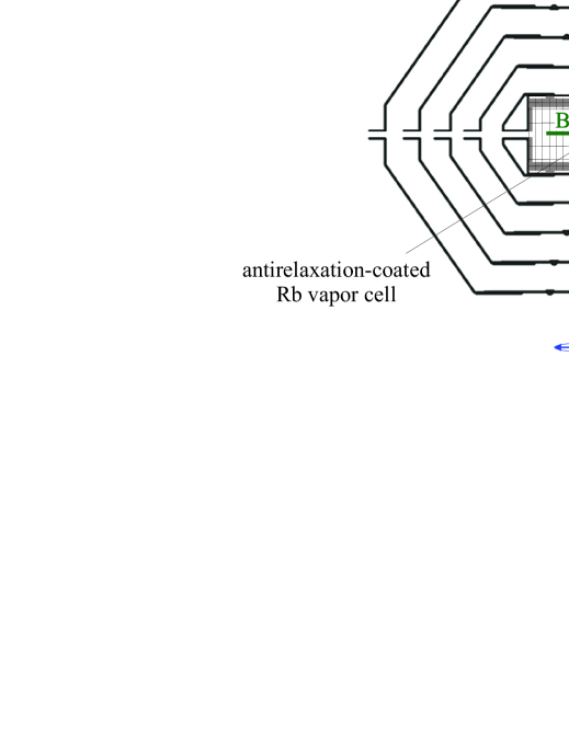
A simplified diagram depicting the experimental setup and geometry is shown in Fig. 1 (further details concerning the experimental apparatus are given in Refs. Jackson Kimball et al. (2009, 2013)). An alkene-coated vapor cell (diameter = 5 cm), containing a natural isotopic mixture of Rb vapor (72% 85Rb, 28% 87Rb), is at the center of a system of coils nested within the innermost layer of a five-layer mu-metal shield Xu et al. (2006); Jackson Kimball et al. (2016). The cell temperature was stabilized at corresponding to a Rb vapor density . The coils enable control of all three orthogonal components of the magnetic field and compensation of all first-order gradients. A magnetic field is applied along the axis, perpendicular to the direction of propagation of the laser beam. Note that this geometry, the so-called Voigt geometry, is different from the Faraday geometry typically used in single-beam NMOR experiments. The major axis of the polarization ellipse of the light is aligned parallel to (along ). The laser light, near-resonant with the Rb D2 transition (), is produced by a tunable external-cavity diode laser (Toptica DL100) and frequency modulated at via sinusoidal laser diode current modulation. The laser beam diameter is . Prior to entering the vapor cell, the probe beam passes through a plate, a linear polarizer, and a plate; these optical elements can be adjusted to control the input light’s intensity and polarization, which are measured using a ThorLABs PAX720IR1-T polarimeter system. The polarimeter (not shown in Fig. 1) is inserted into and removed from the beam path as necessary. After exiting the antirelaxation-coated vapor cell, the beam is analyzed with a polarimeter consisting of a Wollaston prism polarizing beamsplitter whose output rays are detected with an autobalanced photoreceiver (New Focus Nirvana 2007). The signal from the autobalanced photoreceiver is sent to the input of a digital lock-in amplifier (Signal Recovery model 7265) and demodulated at the first harmonic of .
The light ellipticity is defined in terms of the normalized Stokes parameter (see, for example, Ref. Auzinsh et al. (2010) for a detailed discussion):
| (2) |
The optical rotation angle is defined in terms of the normalized Stokes parameters and Auzinsh et al. (2010):
| (3) |
For our experimental geometry
| (4) | ||||
| (5) | ||||
| (6) |
where and are the light intensities along the and axes, and are the light intensities along axes tilted by with respect to the axis, and are the left- and right-hand circular light intensities, respectively, and is the total light intensity.
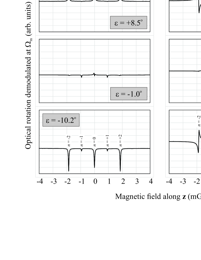
Light linearly polarized along optically pumps atomic spin alignment () along . Since the spin polarization is along , the magnetic torque on the atomic spins is zero; the spin polarization is static and does not precess. If the light is elliptically polarized, it optically pumps both alignment along and orientation () along (depending on its helicity), where is the wave vector of the light. Spins oriented along experience a nonzero torque from and precess. If the light-atom interaction is modulated synchronously with , macroscopic precessing orientation is generated. As the spin orientation precesses, the circular birefringence of the atomic medium is modulated, which in turn generates oscillating optical rotation. This results in EI FM NMOR resonances when , the so-called resonances, as seen in Fig. 2. The plots on the left-hand side show the magnetic-field dependence of the amplitude of the oscillating optical rotation in-phase with the modulation of the light-atom interaction, labeled , and the plots on the right-hand side show the amplitude of the out-of-phase optical rotation, labeled (see, for example, Refs. Jackson Kimball et al. (2009); Malakyan et al. (2004) for more details concerning the in-phase and out-of-phase optical rotation).
The choice of geometry is important for minimization of systematic effects. In the upper plots of Fig. 2 that show the magnetic field dependence of optical rotation for ellipticity , the major axis of the polarization ellipse is apparently well-aligned with . This is evident from the fact that the amplitudes of the FM NMOR resonances are relatively small. On the other hand, noticeable resonances appear in the lower plots of Fig. 2 for , indicating poor alignment of the major axis of the polarization ellipse with . The FM NMOR resonances correspond to the resonance condition, which, as discussed above, is related to atomic spin alignment. Atomic spin alignment can precess if the major axis of the polarization ellipse is tilted with respect to , and in fact can generate both resonances and resonances depending on the tilt with respect to , as discussed in detail in Ref. Pustelny et al. (2006b). Additionally, if optically pumped atomic alignment is tilted with respect to , the phenomenon of alignment-to-orientation conversion Budker et al. (2000b); Jackson Kimball et al. (2009) can occur, where tensor light shifts coupled with Zeeman shifts induce more complicated evolution of the PMs Rochester and Budker (2001). Alignment-to-orientation can generate optical rotation signals that overlap with the EI FM NMOR resonances. Fortunately, the resonances themselves can be used to align the major axis of the polarization ellipse along by making adjustments until their amplitude is minimized. To achieve pure linear polarization, this suggests an iterative process where the FM NMOR resonances are minimized to align with the light polarization axis and the resonances are minimized to bring to zero. The important role of light modulation should be emphasized: for unmodulated light (as used in Ref. Matsko et al. (2003)), there is only a NMOR resonance to which PMs with different all contribute, making their effects difficult to discriminate experimentally.
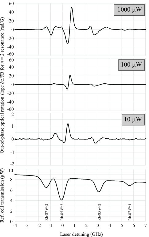
Figure 3 shows the spectral dependence of the EI FM NMOR signals for three representative light powers by plotting the slope of the out-of-phase component of the optical rotation with respect to magnetic field, , evaluated at . Studying helps eliminate the contribution of non--dependent background optical rotation to the spectra, for example that due to self-rotation of the elliptically polarized light Rochester et al. (2001). For reference, the transmission spectrum without laser frequency modulation is displayed at the bottom of Fig. 3 and the corresponding hyperfine components are labeled. At all light powers studied, the largest is obtained when the laser light is detuned to the high frequency wing of the 85Rb transition. Similar results have been found in past NMOR studies Budker et al. (1998, 2000a, 2002b); Jackson Kimball et al. (2009), and are attributed to the role of the bright cycling transition, . When the light is resonant with the transition, atoms are optically pumped into a bright state that interacts more strongly with the light. Another important factor causing the EI FM NMOR signal to be maximized on the slope of a Doppler-broadened optical resonance is that the resonance condition depends on modulation of the light-atom interaction. If the laser is tuned to the center of a Doppler-broadened transition, the light-atom interaction is actually being modulated at which does not fulfill the resonance condition (see the detailed discussion of a similar situation in FM NMOR in Ref. Jackson Kimball et al. (2009)).
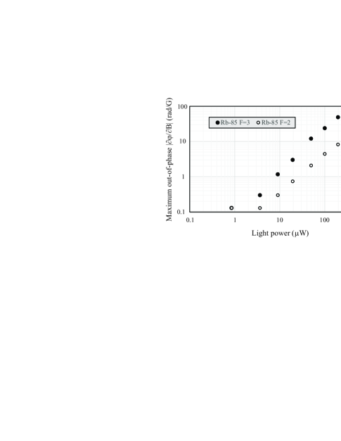
Figure 4 shows the detuning-maximized as a function of incident light power for the 85Rb (filled circles) and 85Rb (unfilled circles) transitions. Note that the maximum as a function of light power occurs near the same power for both transitions () and also that there is a monotonic increase up to the maximum power for both transitions. This is in contrast to the situation for linearly polarized light in the Faraday geometry Budker et al. (2000b); Jackson Kimball et al. (2009), where at sufficiently high light powers, alignment-to-orientation conversion becomes a dominant mechanism causing optical rotation, changing the sign of NMOR and FM NMOR effects and leading to non-monotonic behavior of the detuning-maximized rotation. This is in agreement with the expectation that due to the chosen geometry (major axis of the light polarization ellipse along ), alignment-to-orientation conversion should not play any significant role in EI FM NMOR. The maximum of as a function of light power can be explained by saturation effects related to optical pumping out of the probed ground-state hyperfine level into the unprobed ground-state hyperfine level (see discussions of related saturation phenomena in Refs. Budker et al. (2002a); Budker and Jackson Kimball (2013); Jackson Kimball et al. (2009); Budker et al. (2000a), where maxima occur at similar light powers).
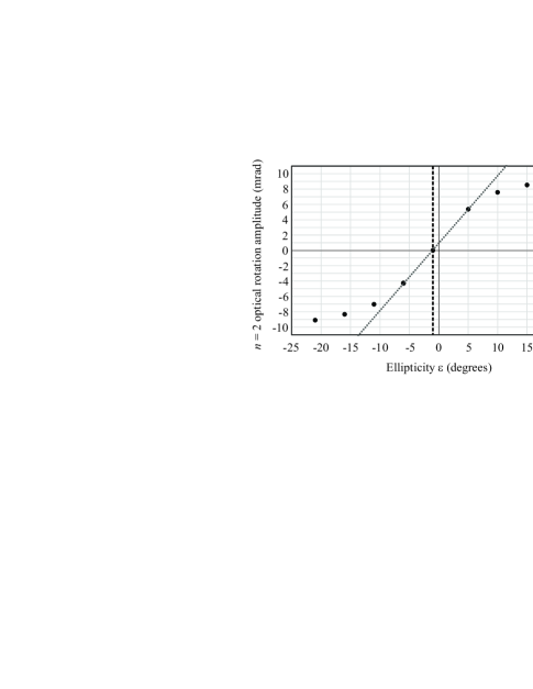
Figure 5 shows the magnitude of the EI FM NMOR in-phase component as a function of for an incident light power of . The light is tuned to the high-frequency wing of the 85Rb transition where EI FM NMOR is maximized. For sufficiently small , we find that
| (7) |
The standard quantum noise limit for polarimetry is
| (8) |
where is the number of photons per second detected by the polarimeter. For a light power of , Eq. (8) gives . Thus we find the projected photon-shot-noise-limited sensitivity to ellipticity is
| (9) |
Shot-noise-limited polarimetry is routinely achieved in experiments using modulated light Birich et al. (1994); Vasilakis et al. (2009); Brown et al. (2010); Jackson Kimball et al. (2013), and in our case our polarimeter is a factor of above the shot-noise limit Jackson Kimball et al. (2009, 2013).
This can be compared to the best existing measurement of ellipticity, that described in Ref. Zhu et al. (2013), which is at the level, but which involves the use ultracold atoms in an optical lattice. The EI FM NMOR technique described here is technically much simpler to implement and, if one averages for only , would represent an improvement in measurement sensitivity to compared to Ref. Zhu et al. (2013) by roughly three orders of magnitude, illustrating the efficiency of EI FM NMOR techniques for ellipticity measurements.
One can also see the offset of the zero-crossing of the EI FM NMOR amplitude from , where was measured for the incident light prior to entering the vapor cell using the ThorLABs PAX720IR1-T polarimeter system. This indicates a systematic offset of from nominal zero inside the cell, presumably caused by birefringence of the cell walls. This demonstrates the usefulness of EI FM NMOR as an in-situ light polarization measurement technique. In fact, EI FM NMOR is used to zero the ellipticity of probe light in order to minimize vector light shifts in our ongoing experiment searching for a spin-gravity coupling Jackson Kimball et al. (2013). We anticipate that this method will be similarly useful in other precision measurements of atomic spin precession.
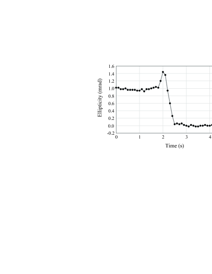
Figure 6 shows a measurement of ellipticity as determined by the calibration shown in Fig. 5, where now is taken to be the zero crossing of . For the data shown in Fig. 6, the light polarization is adjusted by hand to zero the ellipticity by rotating the linear polarizer preceding the plate before the light enters the vapor cell (see Fig. 1). This is the final stage of an iterative process using both the and EI FM NMOR resonances to align the major axis of the polarization ellipse along by minimizing the resonance amplitudes and zeroing the ellipticity by minimizing the resonances. The measured ellipticity, averaged over the last two seconds of data shown in Fig. 6, has an uncertainty of , demonstrating the precision of the method. The precision of the measurement is lower than the shot-noise limit for two reasons: (1) as mentioned above, our polarimeter operates a factor of away from the shot-noise limit due to technical noise, and (2) the light power used in this measurement is rather than , so is a factor of away from its maximum value.
The accuracy with which can be measured is evaluated by consideration of possible systematic errors. Systematic errors due to birefringence of optical elements (such as the vapor cell walls) before and after the atomic sample are negligible since the EI FM NMOR signal is produced by the atoms themselves and has a sharp resonant character in optical frequency, modulation frequency, and magnetic field. As described above, for our geometry where the major axis of the polarization ellipse is along , the symmetry of the system prevents any appearance of resonances occurring at unless . Thus we conclude in principle and observe in practice (see Fig. 2) that the dominant systematic error comes from deviation from this ideal geometry: if the major axis of the polarization ellipse is rotated by an angle with respect to then we observe FM NMOR resonances even when , as discussed in detail in Ref. Pustelny et al. (2006b). However, as noted above, FM NMOR offers a useful tool with which to independently measure and minimize , namely the FM NMOR resonances. Again from symmetry considerations, to first order elliptically polarized light does not affect the amplitude of the FM NMOR resonances since they occur at and are related to atomic spin alignment. If the major axis of the polarization ellipse is aligned along , atomic spin alignment does not precess and thus cannot generate the FM NMOR resonances. Note that in this geometry, alignment-to-orientation effects are also zeroed Budker et al. (2000b); Jackson Kimball et al. (2009). By zeroing the amplitude of the FM NMOR resonances, the misalignment angle can also be zeroed and the primary systematic error can be controlled. The amplitudes of both the non-ellipticity-induced resonances and the resonances scale as for . Using the techniques described in Ref. Pustelny et al. (2006b) we can tune , which generates a FM NMOR resonance amplitude of under our experimental conditions. This translates to a systematic uncertainty in of . This is far below the statistical uncertainty of the measurement shown in Fig. 6 and supports the conclusion that the measurement is statistically limited. After minimization of using this procedure, measurements of vector light shifts in this system are consistent with as discussed in Ref. Jackson Kimball et al. (2013).
In considering the application of EI FM NMOR to other systems of interest (such as cold atoms and nitrogen-vacancy centers in diamonds), we note that since our measurement is statistics-limited, the sensitivity to scales as , where is the number of atoms (in our case ). Another point to be noted is that in our experiment, because the Rb atoms are contained in an evacuated, antirelaxation-coated cell, the quantity measured is in fact the average ellipticity across the light beam, since the atoms are not spatially localized Zhivun et al. (2016). Such motional averaging is reduced in the case of cold atoms, nitrogen-vacancy centers in diamonds, and vapor cells filled with buffer gas. In these cases it should be possible to use EI FM NMOR to study the spatial profile of .
In conclusion, we have introduced and characterized a new in-situ method to measure and control the ellipticity of light interacting with atomic vapors: ellipticity-induced nonlinear magneto-optical rotation of frequency modulated light (EI FM NMOR). This relatively straightforward method can be applied in experiments, for example, where precise and accurate control of vector light shifts is important.
Acknowledgements.
The authors are sincerely grateful to Dmitry Budker, Szymon Pustelny, and Wenhao Li for invaluable discussions, to Mohammad Ali for technical work on parts of the apparatus, and to generations of students who worked on earlier iterations of the experimental apparatus, in particular Rene Jacome, Ian Lacey, Jerlyn Swiatlowski, and Julian Valdez. This work was supported by the National Science Foundation under grants PHY-0652824, PHY-0969666, and PHY-1307507. The findings expressed in this material are those of the authors and do not necessarily reflect those of the NSF.References
- Mathur et al. (1968) B. S. Mathur, H. Tang, and W. Happer, Phys. Rev. 171, 11 (1968).
- Bulos et al. (1971) B. R. Bulos, A. Marshall, and W. Happer, Phys. Rev. A 4, 51 (1971).
- Cohen-Tannoudji and Dupont-Roc (1972) C. Cohen-Tannoudji and J. Dupont-Roc, Phys. Rev. A 5, 968 (1972).
- Happer (1972) W. Happer, Rev. Mod. Phys. 44, 169 (1972).
- Mandel et al. (2003) O. Mandel, M. Greiner, A. Widera, T. Rom, T. W. Hänsch, and I. Bloch, Phys. Rev. Lett. 91, 010407 (2003).
- Lin et al. (2009) Y.-J. Lin, R. L. Compton, K. Jimenez-Garcia, J. V. Porto, and I. B. Spielman, Nature 462, 628 (2009).
- Stamper-Kurn and Ueda (2013) D. M. Stamper-Kurn and M. Ueda, Rev. Mod. Phys. 85, 1191 (2013).
- Wang et al. (2015) Y. Wang, X. Zhang, T. A. Corcovilos, A. Kumar, and D. S. Weiss, Phys. Rev. Lett. 115, 043003 (2015).
- Brennen et al. (1999) G. K. Brennen, C. M. Caves, P. S. Jessen, and I. H. Deutsch, Phys. Rev. Lett. 82, 1060 (1999).
- Chicireanu et al. (2011) R. Chicireanu, K. D. Nelson, S. Olmschenk, N. Lundblad, A. Derevianko, and J. V. Porto, Phys. Rev. Lett. 106, 063002 (2011).
- Sherman et al. (2012) J. A. Sherman, N. D. Lemke, N. Hinkley, M. Pizzocaro, R. W. Fox, A. D. Ludlow, and C. W. Oates, Phys. Rev. Lett. 108, 153002 (2012).
- Jensen et al. (2009) K. Jensen, V. M. Acosta, J. M. Higbie, M. P. Ledbetter, S. M. Rochester, and D. Budker, Phys. Rev. A 79, 023406 (2009).
- Budker and Jackson Kimball (2013) D. Budker and D. F. Jackson Kimball, Optical Magnetometry (Cambridge University Press, 2013).
- Vengalattore et al. (2007) M. Vengalattore, J. M. Higbie, S. R. Leslie, J. Guzman, L. E. Sadler, and D. M. Stamper-Kurn, Phys. Rev. Lett. 98, 200801 (2007).
- Romalis and Fortson (1999) M. V. Romalis and E. N. Fortson, Phys. Rev. A 59, 4547 (1999).
- Jackson Kimball et al. (2013) D. F. Jackson Kimball, I. Lacey, J. Valdez, J. Swiatlowski, C. Rios, R. Peregrina-Ramirez, C. Montcrieffe, J. Kremer, J. Dudley, and C. Sanchez, Annalen der Physik 525, 514 (2013).
- Swallows et al. (2013) M. D. Swallows, T. H. Loftus, W. C. Griffith, B. R. Heckel, E. N. Fortson, and M. V. Romalis, Phys. Rev. A 87, 012102 (2013).
- Zhu et al. (2013) K. Zhu, N. Solmeyer, C. Tang, and D. S. Weiss, Phys. Rev. Lett. 111, 243006 (2013).
- Kastler (1973) A. Kastler, Nuclear instruments and methods 110, 259 (1973).
- Wood et al. (2016) A. A. Wood, L. D. Turner, and R. P. Anderson, Phys. Rev. A 94, 052503 (2016).
- Birich et al. (1994) G. Birich, Y. V. Bogdanov, S. Kanorskii, I. Sobelman, V. Sorokin, I. Struk, and E. Yukov, Journal of Russian Laser Research 15, 455 (1994).
- Durand et al. (2010) M. Durand, J. Morville, and D. Romanini, Phys. Rev. A 82, 031803 (2010).
- Budker et al. (2002a) D. Budker, W. Gawlik, D. F. Kimball, S. M. Rochester, V. V. Yashchuk, and A. Weis, Rev. Mod. Phys. 74, 1153 (2002a).
- Budker and Romalis (2007) D. Budker and M. Romalis, Nature Physics 3, 227 (2007).
- Yashchuk et al. (2003) V. V. Yashchuk, D. Budker, W. Gawlik, D. F. Kimball, Y. P. Malakyan, and S. M. Rochester, Phys. Rev. Lett. 90, 253001 (2003).
- Matsko et al. (2003) A. B. Matsko, I. Novikova, M. S. Zubairy, and G. R. Welch, Phys. Rev. A 67, 043805 (2003).
- Auzinsh et al. (2004) M. Auzinsh, D. Budker, D. F. Kimball, S. M. Rochester, J. E. Stalnaker, A. O. Sushkov, and V. V. Yashchuk, Phys. Rev. Lett. 93, 173002 (2004).
- Petrosyan and Malakyan (2004) D. Petrosyan and Y. P. Malakyan, Phys. Rev. A 70, 023822 (2004).
- Otterstrom et al. (2014) N. Otterstrom, R. Pooser, and B. J. Lawrie, Opt. Lett. 39, 6533 (2014).
- Vasilakis et al. (2009) G. Vasilakis, J. M. Brown, T. W. Kornack, and M. V. Romalis, Phys. Rev. Lett. 103, 261801 (2009).
- Brown et al. (2010) J. M. Brown, S. J. Smullin, T. W. Kornack, and M. V. Romalis, Phys. Rev. Lett. 105, 151604 (2010).
- Griffith et al. (2009) W. C. Griffith, M. D. Swallows, T. H. Loftus, M. V. Romalis, B. R. Heckel, and E. N. Fortson, Phys. Rev. Lett. 102, 101601 (2009).
- Kanorsky et al. (1995) S. Kanorsky, A. Weis, and J. Skalla, Appl. Phys. B 60, S165 (1995).
- Budker et al. (1998) D. Budker, V. Yashchuk, and M. Zolotorev, Phys. Rev. Lett. 81, 5788 (1998).
- Budker et al. (2000a) D. Budker, D. F. Kimball, S. M. Rochester, V. V. Yashchuk, and M. Zolotorev, Phys. Rev. A 62, 043403 (2000a).
- Budker et al. (2002b) D. Budker, D. F. Kimball, V. V. Yashchuk, and M. Zolotorev, Phys. Rev. A 65, 055403 (2002b).
- Balabas et al. (2010) M. V. Balabas, T. Karaulanov, M. P. Ledbetter, and D. Budker, Phys. Rev. Lett. 105, 070801 (2010).
- Chin et al. (2001) C. Chin, V. Leiber, V. Vuletić, A. J. Kerman, and S. Chu, Phys. Rev. A 63, 033401 (2001).
- Bloch (2008) I. Bloch, Nature 453, 1016 (2008).
- Kennedy et al. (2003) T. Kennedy, J. Colton, J. Butler, R. Linares, and P. Doering, Appl. Phys. Lett. 83, 4190 (2003).
- Balasubramanian et al. (2009) G. Balasubramanian, P. Neumann, D. Twitchen, M. Markham, R. Kolesov, N. Mizuochi, J. Isoya, J. Achard, J. Beck, J. Tissler, et al., Nature materials 8, 383 (2009).
- Gawlik et al. (2006) W. Gawlik, L. Krzemień, S. Pustelny, D. Sangla, J. Zachorowski, M. Graf, A. Sushkov, and D. Budker, Appl. Phys. Lett. 88, 131108 (2006).
- Pustelny et al. (2008) S. Pustelny, A. Wojciechowski, M. Gring, M. Kotyrba, J. Zachorowski, and W. Gawlik, J. Appl. Phys. 103, 063108 (2008).
- Pustelny et al. (2006a) S. Pustelny, D. F. Jackson Kimball, S. M. Rochester, V. V. Yashchuk, W. Gawlik, and D. Budker, Phys. Rev. A 73, 023817 (2006a).
- Rochester and Budker (2001) S. M. Rochester and D. Budker, American Journal of Physics 69, 450 (2001).
- Yabuzaki and Ogawa (1974) T. Yabuzaki and T. Ogawa, J. Appl. Phys. 45, 1342 (1974).
- Novikova et al. (2001) I. Novikova, A. B. Matsko, V. L. Velichansky, M. O. Scully, and G. R. Welch, Phys. Rev. A 63, 063802 (2001).
- Patton et al. (2014) B. Patton, E. Zhivun, D. C. Hovde, and D. Budker, Phys. Rev. Lett. 113, 013001 (2014).
- Ben-Kish and Romalis (2010) A. Ben-Kish and M. V. Romalis, Phys. Rev. Lett. 105, 193601 (2010).
- Jackson Kimball et al. (2009) D. Jackson Kimball, L. R. Jacome, S. Guttikonda, E. J. Bahr, and L. F. Chan, J. of Appl. Phys. 106, 063113 (2009).
- Xu et al. (2006) S. Xu, S. M. Rochester, V. V. Yashchuk, M. H. Donaldson, and D. Budker, Rev. Sci. Inst. 77, 083106 (2006).
- Jackson Kimball et al. (2016) D. F. Jackson Kimball, J. Dudley, Y. Li, S. Thulasi, S. Pustelny, D. Budker, and M. Zolotorev, Phys. Rev. D 94, 082005 (2016).
- Auzinsh et al. (2010) M. Auzinsh, D. Budker, and S. Rochester, Optically polarized atoms: understanding light-atom interactions (Oxford University Press, 2010).
- Pustelny et al. (2006b) S. Pustelny, W. Gawlik, S. M. Rochester, D. F. Jackson Kimball, V. V. Yashchuk, and D. Budker, Phys. Rev. A 74, 063420 (2006b).
- Budker et al. (2000b) D. Budker, D. F. Kimball, S. M. Rochester, and V. V. Yashchuk, Phys. Rev. Lett. 85, 2088 (2000b).
- Malakyan et al. (2004) Y. P. Malakyan, S. M. Rochester, D. Budker, D. F. Kimball, and V. V. Yashchuk, Phys. Rev. A 69, 013817 (2004).
- Rochester et al. (2001) S. M. Rochester, D. S. Hsiung, D. Budker, R. Y. Chiao, D. F. Kimball, and V. V. Yashchuk, Phys. Rev. A 63, 043814 (2001).
- Zhivun et al. (2016) E. Zhivun, A. Wickenbrock, J. Sudyka, B. Patton, S. Pustelny, and D. Budker, Optics express 24, 15383 (2016).