Heat diodes made of quantum dots embedded in nanowires connected to metallic electrodes
Abstract
The quantum dot arrays (QDAs) embedded into inhomogeneous nanowires connected to metallic electrodes show an electron heat rectification effect, which is attributed to the thermal voltage arising from a temperature bias and the QDA with a broken spatial inversion symmetry. The staircase energy levels of QDAs can be controlled to the resonant and off resonant transports for electrons in the forward and backward temperature biases, respectively. The effect of electron Coulomb interactions on the rectification efficiency of heat diode is clarified by the case of double QDs. We find that it is important to reduce phonon heat currents for implementing a high efficient electron heat diode at high temperature.
1. Introduction
Solid state heat diodes (HDs) are important for the applications of energy harvesting, which transfers the wasted heats as useful electrical powers.1) Many theoretical efforts have devoted to design HDs.2-14) The rectification efficiency of HDs is defined as , where and are the heat currents in the forward and backward temperature bias, respectively. The ideal HDs will have vanishingly small values, which indicate that heat currents in the backward temperature bias are almost fully blockaded. So far, some systems experimentally show the functionality of HDs, whereas their values are very small.15-19) Most recently was reported in metal/superconductor junction system operated at extremely low temperatures (below the boiling point of liquid helium). Because it is infeasible to directly measure the heat currents, is predicted by the theoretical model without considering phonon heat currents.20) Meanwhile, BCS-type superconductor junctions limit the operation of electron heat diode in a small temperature range.
Unlike electron HDs of ref.[20], some designs have focused on phonon HDs.2-11) In references[2-5] phonon HDs are designed by considering exact one-dimensional systems. Such 1-D models degrade the realistic applications of HDs.6-11) 3-D systems are requested to give a promising application. Although theoretical concepts about the phonon HDs designed in wherever nonlinear interactions and broken inversion symmetry are ubiquitous, currently available techniques have limited sensitivities and are unable to unravel the interesting effect in these phonon systems.12) Therefore, it is desirable to design HDs which are feasible to be measured by thermoelectric technique. Some 3-D semiconductor systems with vacuum layers are proposed to design HDs.13,14,17) Here, we propose the HDs made of quantum dot arrays (QDAs) with staircase energy levels embedded into nanowires connected to metallic electrodes. Unlike phonon HDs,2-11) our design can be applied to energy harvesting for the applications of thermoelectric devices in the nonlinear response regime.21)
2. Formalism
To study the electron heat rectification of QDAs embedded into nanowires connected to metallic electrodes shown in the inset of Fig. 1(a), we start the system Hamiltonian given by an extended Anderson model ,22) where
The first two terms of Eq. (1) describe the free electron gas in the left and right electrodes. () creates an electron of momentum and spin with energy in the left (right) electrode. () describes the coupling between the left (right) QD system and left (right) electrode. () creates (destroys) an electron in the left (right) QD.
where is the spin-independent QD energy level, and , and describe the intradot and the nearest interdot Coulomb interactions, respectively. describes the electron nearest neighbor hopping strength. Because we consider the nanoscale semiconductor QDs, there is only one energy level for each QD.
The electron and heat currents from left (right) electrode to the QDA can be derived by using the Meir-Wingreen formula23). We have
| (3) |
where denotes the Fermi distribution function for the -th electrode, where and are the chemical potential and the temperature of the electrode. , , and denote the electron charge, the Planck’s constant, and the Boltzmann constant, respectively. denotes the transmission coefficient of QDA embedded in a nanowire connected to electrodes. The heat current for electrons leaving from the left (right) electrode is given by
| (4) |
We note that gives a Joule heating.24) To discuss the electron heat rectification, we consider the condition of open circuit () under a temperature bias , where and . denotes the averaged temperature of junction system. Due to the Seebeck effect, the thermal voltage arising from will balance the diffusing electrons from the hot electrode to the cold electrode. Meanwhile, the energy level of each QD will be shifted due to . As a consequence, will depend on .
Because it is difficult to fully blockade phonon heat currents in semiconductor junction systems,1) is considered by an empirical formula in Ref. [25], which allow us to avoid the detailed phonon dispersion structures. It’s expression is given by
| (5) |
where and are the phonon frequency and throughput function, respectively. . We assume that phonon temperature is the same as electron temperature. Dimensionless factor is used to describe the phonon scattering resulting from the interface scattering of QDs embedded into nanowire.26,27) The value of is used through this article. is determined by the theoretical results of ref.[27], where authors calculated the phonon thermal conductance of silicon/germanium QD nanowires. The expression of throughput function is given in Ref. [25], which reads
| (6) |
with the frequency-dependent mean free path given by
| (7) |
where (for ) denotes the number of phonon modes. The dimensionless parameters are chosen to be and .[25] Notation denotes the lattice constant of nanowire. and . is the sound velocity of nanowire and describes the width of the disorder surface of nanowires.24) In Eq. (5), one essentially replaces the frequency-dependent mean free path by a diameter of nanowire () for the high-frequency modes (). The phonon thermal conductance calculated by Eq. (5) under small temperature bias () and well explains the experimental results of silicon nanowires.25,28)
3. Results and discussion
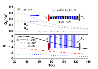
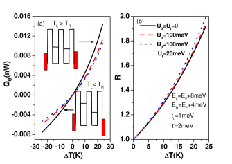
Based on Eq. (3), we numerically solve the thermal voltage () self-consistently by considering the condition of . Substituting into Eq. (4), we can calculate the electron heat current of . For the inhomogeneous nanowire shown in the inset of Fig. 1(a), will depend on the QD location. Here, we assume QDA with staircase energy levels shown in the inset of Fig. 1(b) in which , , and , where is a uniform energy level separation. Due to , will be replaced by , where factor is determined by the QD location, shape and material dielectric constant.29) For the simplicity, is determined by QD location , where denotes the length of QD nanowire. We have the QD location , where is the lattice constant of QD superlattice.27) The parameters of QD number , and are adopted in our calculations. The expression of for N=25 in terms of a single particle retarded Green’s functions can be found in our previous work.30) It is a prohibited challenge to include all correlation functions arising from electron Coulomb interactions for .31,32) The affect of electron Coulomb interactions on the electron transport of double QDs is clarified in Fig. 5 in which we reveal why electron Coulomb interactions can be neglected in this study of . In Fig. 1(a) we show the heat currents as a function of averaged temperature for the forward () and backward () temperature biases () at and . The tunneling rate between the left (right) QD and left (right) electrode is given by . In the wide band limit of electrodes, the energy-dependent can be ignored. Here we have considered . is larger than in the whole temperature range. The heat rectification effect is observed in Fig. 1(b) by . The maximum reaches 1.8 at temperature for . decreases with increasing averaged temperatures at a fixed temperature bias.
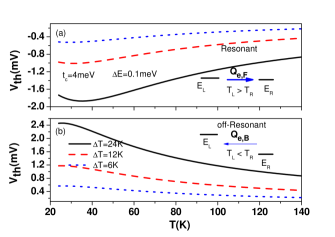
To reveal the mechanism of electron heat rectification of Fig. 1, we plot the thermal voltages in Fig. 2. Note that are negative and positive values in the forward and backward temperature biases, respectively. Nonlinear Seebeck coefficients () are always negative values, which illustrate that electrons of the electrodes mainly diffuse through the energy levels above . The thermal voltage not only changes the chemical potentials of electrodes () to against the diffusing electrons from the hot side to the cold side, but also controls electrons of the electrodes tunneling through resonant and off-resonant channels. In the forward temperature bias the staircase energy levels of QDAs is tuned to quasi resonant channels (see the inset of Fig. 2(a)). On the other hand, QDA energy levels are in the off-resonant channels for backward temperature bias (see the inset of Fig. 2(b)). As a consequence, electron heat current in the is larger than that in . When QDA energy levels are resonant at resulting from a specify , QDA forms a miniband, which is described by the transmission coefficient
| (8) |
depends on QD number. For example, , we have , and . , , , and . , , , , and . satisfies . Eq. (8) clearly illustrates the miniband formed by 25 resonant channels with Lorenz-shape of QD nanowire. When is larger than , this miniband will be lifted.
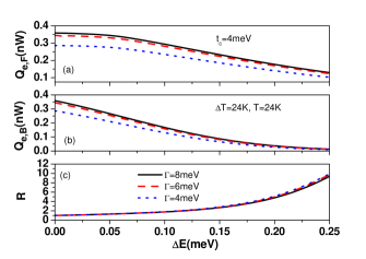
In addition to , the design of staircase energy levels of QDA with broken spatial inversion symmetry also plays a remarkable role to observe the behavior of electron heat rectification. We calculate and as a function of for different tunneling rates in Fig. 3. When (), we see and . This indicates the vanish of rectification effect when QDA energy levels have a spatial inversion symmetry. and decrease with increasing , whereas decreases quickly. As a consequence, is highly enhanced. As for the variation of tunneling rates, electron heat currents is reduced with decreasing . Nevertheless, is not sensitive to the variation of .
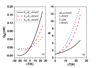
For a heat diode, one has to examine the behavior of heat current as a function of temperature bias.2-14 We plot as a function of for different values at a averaged temperature () in Fig. 4(a). Electron heat currents show a manifested rectification behavior since is much larger than . However, is suppressed with increasing . When QD energy levels are tuned away from , electron population decreases and then is reduced. In addition, the negative differential thermal conductance (NDTC) feature, which decreases with increasing , exists in the backward temperature bias regime. In Fig. 4(b) values are larger than ten for dotted and dashed curves in the regime of . Although values are smaller than those reported in ref. [20], the operation averaged temperature is much higher than that of ref.[20].
In the previous figures, electron Coulomb interactions are not included in calculations. We have to examine the effect of electron Coulomb interactions on the electron heat rectification. To clarify the effect of electron intradot and interdot Coulomb interactions on , the electron heat currents and values of double QDs (DQDs) as a function of temperature bias for different electron Coulomb interactions are plotted in Fig. 5. The expression of for DQDs can be found in ref [31,28]. In Fig. 5(a) electron heat currents are suppressed in the presence of electron Coulomb interactions. Such an effect is more significant at large due to the increase of electron population. Because and are above , we can consider the approximated expression of as
| (9) |
where and . is the probability weight of double QDs with empty state, which is determined by the one particle occupation numbers and other correlation functions.28,31 Other resonant levels arising from intradot and interdot Cooulomb interactions are very far away from can be ignored in Eq. (9). If one turns off electron Coulomb interactions, . From the results of Fig. 5(a), is just slightly reduced. This indicates that the calculations of figures (1)-(4) will be slightly changed as long as , which is the regime we are interested in. Fig. 5(b) show the rectification efficiency for different electron Coulomb interaction configurations. Although is suppressed in the presence of and , is enhanced. This enhancement due to electron Coulomb interactions will disappear in the presence of phonon heat currents.
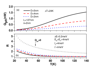
Although a vacuum layer allow high efficient electron HDs operated at room temperature, it increases the technique complication.14) Finally, we clarify how phonon heat currents to influence the electron heat rectification. Based on Eq. (5), we calculate as a function of averaged temperature for different diameters of silicon/germanium QD nanowires at a fixed temperature bias and disorder surface width in Fig. 6(a). The behavior of can be understood by , where is phonon thermal conductance. Therefore, Fig. 6(a) reveals that increases with increasing averaged temperature.25,28) Such a temperature behavior of between and is not limited in the silicon/germanium QD systems, but the typical feature of nanowires with surface disorder effects.1,25) Phonon heat currents decrease with decreasing . The values are smaller than as , but their magnitudes are comparable to . To evaluate , obviously we have to include the phonon heat currents. In Fig. 6(b) we calculate for different values at . In the absence of , we observe that is larger than 3 when is below . Once is included, is suppressed seriously. The results of Fig. 6(b) imply that it is crucial to have phonon glass materials33-35) or some novel ideas (for example phonon localization) to fully blockade for high efficient electron heat diodes. Because silicon and germanium are not polar semiconductors, the electron phonon interactions (EPIs) are vanishingly small in a finite length nanowire. Therefore, we can ignore the effect of EPIs on electron and phonon heat currents.
4. Conclusion
We have theoretically investigated the electron heat rectification of QDA embedded into a nanowire. The staircase energy levels with a broken spatial inversion symmetry and thermal voltage resulting from temperature biases play a remarkable role to observe electron heat rectification effect. The staircase energy levels of QD nanowire may be achieved by considering inhomogeneous QD nanowire shown in Fig. 1(a). Recently, we have demonstrated that the electron conductance and electron thermal conductance of DQDs can be highly enhanced by increase of level degeneracy.28) The rectification efficiency of electron HDs may be enhanced based on level degeneracy.
Acknowledgments
This work was supported by the Ministry of Science and Technology
of Taiwan under Contract No. MOST 103-2112-M-008-009-MY3
E-mail address: mtkuo@ee.ncu.edu.tw
References
- (1) A. J.Minnich,M. S.Dresselhaus,Z.F.Ren, and G. Chen: Energy Environ Sci. 2, (2009) 466.
- (2) M. Terraneo, M. Peyrard, and G. Casati: Phys. Rev. Lett. 88, (2002) 094302.
- (3) B. W. Li, L. Wang, and G. Casati: Phys. Rev. Lett. 93, (2004) 184301 .
- (4) B. W. Li, J. H. Lan, and L. Wang: Phys. Rev. Lett. 95, (2005) 104302 .
- (5) D. Segal and A. Nitzan: Phys. Rev. Lett. 94, (2005) 034301.
- (6) J. H. Lan and B. W. Li: Phys. Rev. B 74, (2006) 214305.
- (7) G. Casati, C. Mejia-Monasterio, and T. Prosen: Phys. Rev. Lett. 98, (2007) 104302.
- (8) Y. Wang, A. Vallabhaneni, J. N. Hu, B. Qiu, Y. P. Chen, and X. L. Ruan: Nano Lett. 14, (2014) 592.
- (9) S. Pal and I. K. Puri: Nanotechnology 25, (2014) 8.
- (10) X. Cartoixa, L. Colombo, and R. Rurali: Nano Lett. 15, (2015) 8255 .
- (11) Y. Li, X. Y. Shen, Z. H. Wu, J. Y. Huang, Y. X. Chen, Y. S. Ni, and J. P. Huang: Phys. Rev. Lett. 115, (2015) 195503.
- (12) C. L. Chiu, C. H. Wu, B. W. Huang, C. Y. Chien and C. W. Chang: AIP ADVANCES 6, (2016) 121901.
- (13) C. R. Otey, W. T. Lau, and S. H. Fan: Phys. Rev. Lett. 104, (2010) 154301.
- (14) D. M.-T. Kuo and Y. C. Chang: Phys. Rev. B 81, (2010) 205321.
- (15) C. W. Chang, D. Okawa, A. Majumdar, and A. Zettl: Science 314, (2006) 1121.
- (16) R. Scheibner, M. Konig, D. Reuter, A. D. Wieck, C. Gould, H. Buhmann, and L. W. Molenkamp: New J. Phys. 10, (2008) 083016.
- (17) K. Ito, K. Nishikawa, H. Iizuka, and H. Toshiyoshi: Appl. Phys. Lett. 105, (2014) 253503.
- (18) J. Zhu, K. Hippalgaonkar, S. Shen, K. V. Wang, Y. Abate, S. Lee, J. Q. Wu, X. B. Yin, A. Majumdar, and X. Zhang: Nano Lett. 14, (2014) 4867.
- (19) Z. Chen, C. Wong, S. Lubner, S. Yee, J. Miller,W. Jang, C. Hardin, A. Fong, J. E. Garay, and C. Dames: Nat. Commu. 5, (2014) 5.
- (20) M. J. Martinez-Perez, A. Fornieri, and F. Giazotto: Nature Nanotech. 10, (2015) 303.
- (21) D. Sanchez and R. Lopez: C. R.Physique 17, (2016) 1060.
- (22) H. Haug and A. P. Jauho: Quantum Kinetics in Transport and Optics of Semiconductors (Springer, Heidelberg, 1996).
- (23) Y. Meir and N. S. Wingreen: Phys. Rev. Lett. 68, (1992) 2512.
- (24) K. Yamamoto and N. Hatano: Phys. Rev. E, 92, (2015) 042165.
- (25) R. K. Chen, A. I. Hochbaum, P. Murphy, J. Moore, P. D. Yang, and A. Majumdar: Phys. Rev. Lett. 101, (2008) 105501.
- (26) D. L. Nika, E. P. Pokatilov, A. A. Balandin, V. M. Fomin, A. Rastelli, and O. G. Schmidt: Phys. Rev. B 84, (2011) 165415.
- (27) Ming Hu and Dimos Poulikakos: Nano Lett. 12, (2012) 5487.
- (28) D. M. T. Kuo, C. C. Chen, and Y. C. Chang: Phys. Rev. B 95, (2017) 075432.
- (29) David M. T. Kuo and Yia-chung Chang, Phys. Rev. B 89, 115416 (2014).
- (30) D. M. T. Kuo and Y. C. Chang: Nanotechnology, 24, (2013) 175403.
- (31) D. M.-T. Kuo, S. Y. Shiau and Y. C. Chang: Phys . Rev. B 84, (2011) 245303.
- (32) C. C. Chen, D. M.-T. Kuo and Y. C. Chang: Phys. Chem. Chem. Phys. 17, (2015) 19386.
- (33) T. Zhu and E. Ertekin: Phys. Rev. B 90, (2014) 195209.
- (34) T. Zhu and E. Ertekin: Phys. Rev. B 93, (2016) 155414.
- (35) T. Zhu and E. Ertekin: Nano Lett. 16. (2016) 4763.