Understanding the Computational Requirements of Virtualized Baseband Units using a Programmable Cloud Radio Access Network Testbed
Abstract
Cloud Radio Access Network (C-RAN) is emerging as a transformative architecture for the next generation of mobile cellular networks. In C-RAN, the Baseband Unit (BBU) is decoupled from the Base Station (BS) and consolidated in a centralized processing center. While the potential benefits of C-RAN have been studied extensively from the theoretical perspective, there are only a few works that address the system implementation issues and characterize the computational requirements of the virtualized BBU. In this paper, a programmable C-RAN testbed is presented where the BBU is virtualized using the OpenAirInterface (OAI) software platform, and the eNodeB and User Equipment (UEs) are implemented using USRP boards. Extensive experiments have been performed in a FDD downlink LTE emulation system to characterize the performance and computing resource consumption of the BBU under various conditions. It is shown that the processing time and CPU utilization of the BBU increase with the channel resources and with the Modulation and Coding Scheme (MCS) index, and that the CPU utilization percentage can be well approximated as a linear increasing function of the maximum downlink data rate. These results provide real-world insights into the characteristics of the BBU in terms of computing resource and power consumption, which may serve as inputs for the design of efficient resource-provisioning and allocation strategies in C-RAN systems.
Index Terms:
Cloud Radio Access Network; Testbed; Software-Defined Radio; Network Virtualization; Profiling; LTE.I Introduction
Cloud Radio Access Network (C-RAN) [1] has been introduced as a revolutionary redesign of the cellular architecture to address the increase in data traffic and to reduce the capital expenditure (CAPEX) and operating expenditure (OPEX) [2]. The idea of C-RAN is to decouple the computational functionalities from the distributed BS (a.k.a. eNodeB in LTE) and to consolidate them in a centralized processing center. A typical C-RAN is composed of: (i) light-weight, distributed Radio Remote Heads (RRHs) plus antennae, which are located at the remote site and are controlled by a centralized virtual base station pool, (ii) the Base Band Unit (BBU) composed of high-speed programmable processors and real-time virtualization technology to carry out the digital processing tasks, and (iii) low-latency high-bandwidth optical fibers, which connect the RRHs to the BBU pool. In a centralized BBU pool, since information about the network resides in a common place, the BBU can exchange control data at rate. By exploiting the global view of the network condition and traffic demand available at the BBU, dynamic provisioning and allocation of spectrum, computing, and radio resources can improve network performance [3, 4, 5, 6, 7, 8]. Interestingly, C-RAN paves the way for bridging the gap between two so-far disconnected worlds: cellular communications and cloud computing.
In a BBU pool, most of the communication functionalities are implemented in part or fully in a virtualized environment hosted over general-purpose computing servers and can be realized using Virtual Machines (VMs). The flexible reconfigurability of the virtualized BBU allows for it to be dynamically resized ‘on the fly’ in order to meet the fluctuations in capacity demands. This elasticity will enable significant improvement in user Quality of Service (QoS) and efficiency in energy and computing resource utilization in C-RANs. However, determining the computational resources of a virtualized BBU (VM) that is capable of providing adequate processing capabilities with respect to the traffic load presents non-trivial challenges.
Our vision: We seek to characterize the computational requirements of virtualized BBUs over a real-world implementation of a small-scale C-RAN system. Software implementations coupled with real-hardware experiments is essential to understand the runtime complexity as well as performance limits of the BBU in terms of processing throughput and latency and how they translate into mobile-user QoS metrics. The realization of the C-RAN emulation testbed on virtualized general-purpose computing servers will allow for profiling of the computational complexity of the different communication functionalities implemented in software. In particular, such profiling results will provide a “mapping” from the number and combination of different types of user traffic to VM computational capacity. Hence, we aim at establishing empirical models for the estimation of processing time and CPU utilization with respect to different radio-resource configurations and traffic load. Our model will provide researchers and practitioners with real-world insights and the necessary tools for designing advanced and efficient resource-provisioning and allocation strategies in C-RAN systems.
Related works: There has been a considerable number of works addressing the benefits of C-RAN from the cooperative communications perspectives. For instance, the work in [9] consider the power minimization problem by jointly optimizing the set of active RRHs and precoding or beamforming design. In addition, the optimal tradeoff between transmission power and delay performance is investigated in [10] via a cross-layer based approach, taking into account the imperfect channel information. Furthermore, the works in [11, 12] address the front-haul uplink compression problem in C-RAN. While showing promising performance gains brought by the centralized cooperation and network optimization C-RAN, these works often overlook the system issues and mostly rely on simplified assumptions when modeling the computational resources of the BBU. From the system perspectives, several LTE RAN prototypes have been implemented over General-Purpose Platforms (GPPs) such as the Intel solutions based on hybrid GPP-accelerator [13], Amarisoft solution [14], and OpenAirInterface platform [15]. Studies on these systems have demonstrated the preliminary potential benefits of C-RAN in improving statistical multiplexing gains, energy efficiency, and computing resource utilization. Field-trial results in [1, 16] show the feasibility of deploying C-RAN front-haul using CPRI compression, single fiber bidirection, and wavelength-division multiplexing. The authors in [17] focus on the issue of minimizing computational and networking latencies by VMs or containers. Kong et al. [18] present the architecture and implementation of a BBU cluster testbed to improve energy efficiency in C-RAN. Wu [19] shows a high-level architecture for programmable RAN (PRAN) that centralizes base stations’ L1/L2 processing of BBU pool onto cluster of commodity servers. This approach shows the feasibility of fast data path control and efficiency of resource pooling. In summary, these works focus on the overall system architecture, feasibility of virtual software BS stacks, performance requirements, and analysis of optical links between the RRHs and the BBU cloud. However, most of these systems are either proprietary or ad-hoc based, and do not provide a generalized characterization that facilitates research on new algorithms.
Our contributions: Given the importance of designing effective resource-management solutions in C-RAN and the lack of experimental studies into the computational performance and requirements of the BBU pool, we make the following contributions in this paper.
-
•
We present the design and implementation of a programmable C-RAN testbed comprising of a virtualized BBU connected to multiple eNodeBs (eNBs). In particular, the BBU is implemented using an open-source software platform OpenAirInterface (OAI) that allows for simulation and emulation of the LTE protocol stack. The eNBs are realized using programmable USRP boards.
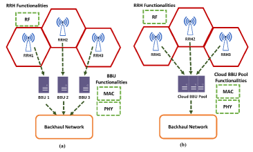
Figure 1: (a) Each BBU is assigned to one RRH, (b) Consolidated BBU. -
•
We perform extensive experiments with transmissions between the eNB and the UE under various configurations in order to profile the runtime complexity and performance limits of the BBU in terms of processing, throughput, and latency. It is shown that the processing time and CPU utilization of the BBU increase with the Modulation and Coding Scheme (MCS) index and with the number of allocated Physical Resource Blocks (PRBs).
-
•
Using empirical data, we model the BBU processing time as a function of the CPU frequency, MCS, and PRBs, and show that the CPU utilization percentage of the BBU can be well approximated as a linear increasing function of the maximum downlink data rate. These approximated models provide real-world insights and key inputs to formulate, design, and evaluate optimized resource-management problems in C-RAN.
II System Overview
We describe here the C-RAN system architecture and the OAI software platform that is capable of realizing a virtualized C-RAN system.
II-A C-RAN Architecture
The general architecture of C-RAN mainly consists of two parts: the distributed RRHs plus antennae deployed at the remote site and the centralized BBU pool hosted in a cloud datacenter. The BBU pool consists of multiple BBUs, each hosted on a VM and connected to the corresponding RRH via high-bandwidth low-latency media (e.g., use of optic fibers allows for maximum distance separation of between the RRH and its BBU [1]). Packet-level processing, Medium Access Control (MAC), physical-layer (PHY) baseband processing, and Radio Frequency (RF) functionalities may be split between the BBU and the RRHs depending on the specific C-RAN implementation. In this paper, we consider the full centralization of C-RAN in order to exploit fully the potential of this paradigm where only RF functionalities are deployed at the RRHs. Based on the network performance and system implementation complexity, each BBU can be assigned to one RRH, as shown in Fig. 1(a) or the BBUs can be consolidated into one entity, called BBU pool as depicted in Fig. 1(b).
II-B Emulation Platform
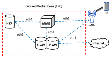
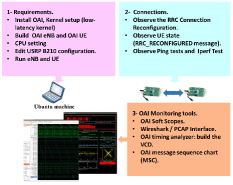
We choose an open-source software implementation of LTE standard called OpenAirInterface (OAI) [15] developed by EUROCOM to realize the virtualized C-RAN system. OAI can be used to build and customize mobile network operators consisting of eNBs and Commercial off-the-shelf (COST) UEs as well as software-defined UEs. The structure of OAI mainly consists of two components: one part, called , is used for building and running eNB units; the other part, called -, is responsible for building and running the Evolved Packet Core (EPC) networks, as shown in Fig. 2. The - component provides a programmable environment to implement and manage the following network elements: Mobility Management Entity (MME), Home Subscriber Server (HSS), Serving Gateway (S-GW), and PDN Gateway (P-GW).
 |
|
|
| (a) | (b) | (c) |
III C-RAN Experimental Testbed
We detail now our C-RAN testbed using OAI, including the testbed architecture, configuration, and experiment methods.
III-A Testbed Architecture
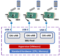
Figure 3(a) illustrates the architecture of our testbed. The RRH front-ends of the C-RAN testbed are implemented using SDR USRP B210s, each supporting MIMO with sample rate up to . In addition, each radio head is equipped with a GPSDO module for precise synchronization. Each instance of the virtual BBU is implemented using the OAI LTE stack, which is hosted in a VMware VM. All the RRHs are connected to the BBU pool (the physical servers hosting the VMs) via USB connections.
The Ubuntu LTS with kernel -- is used for both host and guest operating systems. In order to achieve a high performance for our testbed, all power-management features in the BIOS, C-states, and CPU frequency scaling have been turned off. The CPU should support the and features. These flags must be exposed from the host to the guest, and can be checked by using the command . For the physical sever hosting the BBU, we use a Dell Precision T5810 workstation with Intel Xeon CPU E5-1650, 12-core at , and RAM. There are several configurations that depend on the guest OS’s specific setup that should be calibrated in order to boost the performance of the testbed. Most importantly, the maximum transmit power at the eNB and the UE can be calibrated as follows.
-
•
eNB: The maximum transmit power at the eNB is signaled to the UE so that it can do its power control. The parameter is PDSCH Energy Per Resource Element (EPRE) and it is part of the configuration file, . It should be measured using a vector signal analyzer with LTE option for the utilized frequency and then put in the configuration file.
-
•
UE: At the UE, the maximum transmit power is measured over the whole (usable) bandwidth. If the same hardware is used at the UE and at the eNB, the power is .
III-B Monitoring the OAI eNB and the UE
As illustrated in Fig. 3(b), our C-RAN experimental testbed consists of one unit of UE and one unit of eNB, both implemented using the USRP B210 boards and running on OAI. The OAI software instances of the eNB and UE run in separate Linux-based Intel x86-64 machines comprising of 4 cores for UE and 12 cores for eNB, respectively, with Intel i7 processor core at .
OAI comes with useful monitoring tools such as network protocol analyzers, loggers, performance profilers, timing analyzers, and command line interfaces for performing the intended measurements and monitoring of the network. Specifically, the supported monitoring tools include:
-
•
OAI Soft Scope, which monitors received-transmitted waveforms and also tracks the channel impulse response.
-
•
WireShark Interface and ITTI Analyzer, which can be used to analyze the exchanges between eNB and UE protocols.
-
•
OpenAirInterface performance profiler, which is used for processing-time measurements.
| Parameters | eNB | UE |
|---|---|---|
| Duplexing mode | FDD | FDD |
| Frequency | ||
| Transmitted power | ||
| MCS | ||
| Mobility | Static | Static |
| PRB | ||
| Radiation pattern | Isotropic | Isotropic |
Figure 3(c) illustrates the OAI processing flow for building, running, and monitoring stages. In addition, we summarize the testbed configuration parameters in Table I. In particular, the eNB is configured in band 7 (FDD) and the transmission bandwidth can be set to , , and , corresponding to , , and , respectively. In order to determine the successful connection between eNB and UE, the RRC states should be observed in OAI console. Specifically, when the UE is successfully paired to the eNB, the RRC connection setup message should be seen.
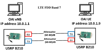
III-C Interference-free Testbed Environment
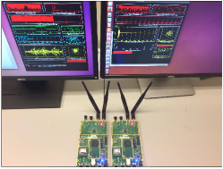
We set up the experiment environment to emulate a “quiet” transmission between the eNB and UE in which there is no interference from other devices (so to have better control of the environment). To accomplish this, we use two configurable attenuators, model name Trilithic Asia 35110D-SMA-R, which connect the Tx and Rx ports of the eNB to the Rx and Tx ports of the UE, respectively, as shown in Fig. 4. In order to establish a stable connection, the transmitter and received gains in the downlink have been set to and , respectively.
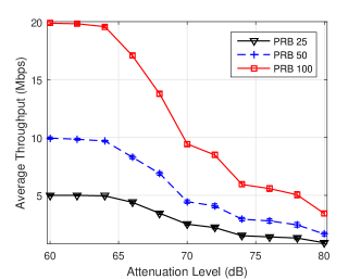
We use to generate packets to send from the eNB to the UE. Figure 5 illustrates the throughput performance versus the attenuation level between the eNB and UE. It can be seen that the achievable throughput significantly decreases with attenuation level. Specifically, when the attenuation level is the achievable throughputs are around , , and when using , , and PRBs, respectively. On the other hand, at an attenuation of , the throughputs are much lower, i.e., , , and , respectively. We observe that the eNB-UE connection will drop when the attenuation level goes higher than .
IV Experimental Results and Empirical Models
We present the performance of the virtualized BBU, i.e., the OAI eNB, in terms of packet delay, CPU processing time, and utilization under various PRB and MCS configurations.
IV-A Delay Performance
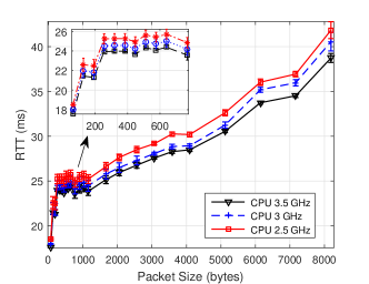
To test the delay in the C-RAN testbed, we focus on measuring the RTT when sending packets between the eNB and the UE. The VM hosting the BBU is configured with virtual cores and RAM in a VMware hypervisor, running on a physical machine with cores, CPU, and RAM. The OAI UE runs on a low-latency Ubuntu physical machine with CPU and RAM. Figure 6 illustrates the relationship between RTT and packet size when the BBU is set at different CPU frequencies. For each experiment, we sent Internet Control Message Protocol (ICMP) echo request packets from the eNB to the UE. It can be seen that the RTT exponentially increases as the packet size increases. Moreover, we have also noted that the RTT is greater when OAI eNB runs on a VM than on a physical machine, which may be due to the overhead incurred when running the VM. In addition, there is a correlation between the CPU frequency and the OAI software performance. We have recorded that the minimum CPU threshold frequency to run OAI in our scenario is . Below the threshold value, we observed that the synchronization between eNB and UE is occasionally missed. By controlling the CPU frequency using the tool, we have noticed that the RTT can be improved by increasing the CPU frequency steps.
IV-B Processing Time of LTE Subframes
In this section, we study the BBU processing time of each LTE subframe with respect to different CPU frequency configurations in the VMware environment. The execution time of each signal processing module in the downlink is measured using timestamps at the beginning and at the end of each subframe. OAI uses the RDTSC instruction implemented on all x86 and x64 processors as of the Pentium processors to achieve precise timestamps [20]. The tool in Linux is used to control the available CPU frequencies. To avoid significant delay and to not miss the synchronization between eNB and UE hardware, we recommend to run the experiment within a CPU frequency range.
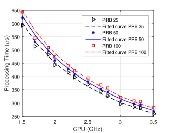
In Fig. 7, we depict the processing time of the eNB given different CPU-frequency steps, in which the MCS index is set to for both UL and DL. It can be seen that the processing time dramatically decreases when the CPU frequency increases. To model the subframe processing time against the CPU frequency and radio-resource configuration, we repeat the experiment in Fig. 7 with different MCS indexes. The subframe processing time can be well approximated as a function of CPU frequency , MCS, and PRB as,
| (1) |
where and are two parameters that increase with PRB and MCS values as reported in Table II.
![[Uncaptioned image]](/html/1706.06251/assets/x10.png)
IV-C CPU Utilization
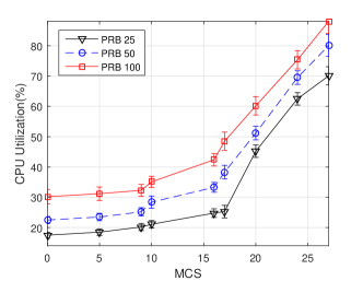
In C-RAN, it is of critical important to understand the CPU utilization of the BBU in order to design efficient resource provisioning and allocation schemes. In the previous subsections, we have seen the relationship between MCS and CPU usage for different values of PRBs. In this experiment, the CPU utilization percentage is calculated using the command in Linux, which is widely used to display processor activities as well as various tasks managed by the in real time. We repeatedly send UDP traffic from the eNB to the UE with various MCS and PRB settings. The CPU utilization percentage has been recorded as in Fig. 8. By setting the CPU frequency of the OAI eNB to , we have seen that the highest CPU consumption occurred at MCS , corresponding to , , and when PRBs are , , and , respectively. We can conclude that the total processing time and computing resources were mainly spent on the modulation, demodulation, coding, and decoding. These tasks played the bigger roles in terms of complexity and runtime overhead in the BBU protocol stack.
To understand better the BBU computational consumption in C-RAN with respect to the users’ traffic demand, we will now establish the relationship between the DL throughput and the percentage of CPU usage at the BBU. To begin, we learn that OAI supports different MCSs with index ranging from to . In the downlink direction, MCSs with the index to are modulated using QPSK, index to are modulated using 16-QAM, and the rest are based on 64-QAM. For instance, in LTE FDD system with PRB , corresponding to bandwidth of , we can get symbols per , in case of normal Cyclic Prefix (CP) [21], which is equivalent to a data rate of . Based on the MCS index used in each experiment, we can calculate the corresponding DL throughput by multiplying the bit rate by the number of bits in the modulation scheme.
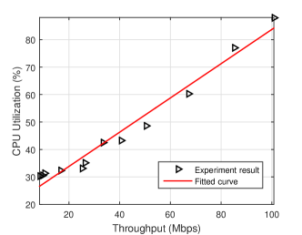
Figure 9 shows the CPU utilization percentage at the BBU corresponding to different DL throughputs. Using the calculated results, we have fitted the CPU utilization as a linear function of the DL throughput as,
| (2) |
where is the throughput measured in .
V Conclusions
To exploit the benefits of C-RAN, software implementation coupled with real-hardware experiments is essential to understand the runtime complexity and performance limits of virtual Baseband Units (BBUs). We studied and analyzed several aspects related to the practical implementation of the C-RAN architecture to support 5G systems. First, we presented the main C-RAN testbed implementation challenges and studied several virtualization approaches. Second, by using an OAI emulation platform, we built the eNB and UE on low-latency Linux VMs. Experiments were carried out to evaluate the BBU performance under various computing and radio-resource configurations. Our experimental results showed that the frame processing time and CPU utilization of the BBU increase with the PRB resource and MCS index. Third, based on these results, we established empirical models for the estimation of the BBU processing time as a function of CPU frequency, MCS, and PRB index, as well as for the BBU’s CPU usage as a linear function of the downlink throughput. These models provide real-world insights into the computational requirements of the BBU, and may serve as key inputs for the design of resource-management solutions in C-RAN systems.
Acknowledgments: This work was partially supported by the US National Science Foundation Grant No. CNS-1319945.
References
- [1] China Mobile Research Institute, “C-RAN: The Road Towards Green RAN,” White Paper, Sept. 2013.
- [2] J. Wu, Z. Zhang, Y. Hong, and Y. Wen, “Cloud radio access network (C-RAN): a primer,” IEEE Network, vol. 29, no. 1, pp. 35–41, 2015.
- [3] T. X. Tran and D. Pompili, “Dynamic Radio Cooperation for Downlink Cloud-RANs with Computing Resource Sharing,” in Proc. IEEE Int. Conf. on Mobile Ad hoc and Sensor Systems (MASS), pp. 118–126, Oct. 2015.
- [4] D. Pompili, A. Hajisami, and T. X. Tran, “Elastic resource utilization framework for high capacity and energy efficiency in Cloud RAN,” IEEE Commun. Mag., vol. 54, no. 1, pp. 26–32, 2016.
- [5] T. X. Tran and D. Pompili, “Octopus: A Cooperative Hierarchical Caching Strategy for Cloud Radio Access Networks,” Proc. of the IEEE Intl. Conf. on Mobile Ad hoc and Sensor Systems (MASS), pp. 154–162, Oct. 2016.
- [6] T. X. Tran and D. Pompili, “Dynamic Radio Cooperation for User-Centric Cloud-RAN with Computing Resource Sharing,” IEEE Trans. on Wireless Commun., vol. 16, no. 4, pp. 2379–2393, 2017.
- [7] P. Luong, C. Despins, F. Gagnon, and L.-N. Tran, “A fast converging algorithm for limited fronthaul C-RANs design: Power and throughput trade-off,” in Proc. IEEE Int. Conf. Commun. (ICC), May 2017.
- [8] M.-P. Hosseini, H. Soltanian-Zadeh, K. Elisevich, and D. Pompili, “Cloud-based deep learning of big eeg data for epileptic seizure prediction,” in Proc. IEEE Global Conference on Signal and Information Processing (GlobalSIP), pp. 1151–1155, 2016.
- [9] P. Luong, L.-N. Tran, C. Despins, and F. Gagnon, “Joint beamforming and remote radio head selection in limited fronthaul C-RAN,” in Proc. IEEE Veh. Tech. Conf. (VTC-Fall), pp. 1–6, 2016.
- [10] T. X. Tran, A. Hajisami, and D. Pompili, “QuaRo: A Queue-Aware Robust Coordinated Transmission Strategy for Downlink C-RANs,” in Proc. IEEE Int. Conf. on Sensing, Commununications, and Networking (SECON), pp. 441–449, June 2016.
- [11] T. X. Vu, H. D. Nguyen, and T. Q. Quek, “Adaptive compression and joint detection for fronthaul uplinks in cloud radio access networks,” IEEE Trans. Commun., vol. 63, no. 11, pp. 4565–4575, 2015.
- [12] K.-G. Nguyen, Q.-D. Vu, M. Juntti, and L.-N. Tran, “Energy efficient precoding C-RAN downlink with compression at fronthaul,” in Proc. IEEE Int. Conf. Commun. (ICC), May 2017.
- [13] R. Schooler, “Transforming networks with NFV and SDN,” Intel Architecture Group, 2013.
- [14] “Amarisoft LTE software base station.” Available: http://www.amarisoft.com/?p=amarilte.
- [15] EURECOM, “Open air interface.” Available: http://www.openairinterface.org/, Oct. 2014.
- [16] C.-L. I, J. Huang, R. Duan, C. Cui, J. Jiang, and L. Li, “Recent Progress on C-RAN Centralization and Cloudification,” IEEE Access, vol. 2, pp. 1030–1039, 2014.
- [17] C.-N. Mao, M.-H. Huang, S. Padhy, S.-T. Wang, W.-C. Chung, Y.-C. Chung, and C.-H. Hsu, “Minimizing latency of real-time container cloud for software radio access networks,” in Proc. IEEE Int. Conf. on Cloud Computing Technology and Science (CloudCom), pp. 611–616, 2015.
- [18] Z. Kong, J. Gong, C.-Z. Xu, K. Wang, and J. Rao, “ebase: A baseband unit cluster testbed to improve energy-efficiency for cloud radio access network,” in Proc. IEEE Int. Conf. on Commun. (ICC), pp. 4222–4227, 2013.
- [19] W. Wu, L. E. Li, A. Panda, and S. Shenker, “Pran: Programmable radio access networks,” in Proc. ACM Workshop on Hot Topics in Networks, p. 6, 2014.
- [20] I. Alyafawi, E. Schiller, T. Braun, D. Dimitrova, A. Gomes, and N. Nikaein, “Critical issues of centralized and cloudified lte-fdd radio access networks,” in Proc. IEEE Int. Conf. on Commun. (ICC), pp. 5523–5528, 2015.
- [21] E. Dahlman, S. Parkvall, and J. Skold, 4G: LTE/LTE-advanced for mobile broadband. Academic press, 2013.