Characterizing Lifting and Lowering Activities with Insole FSR sensors in Industrial Exoskeletons
Abstract
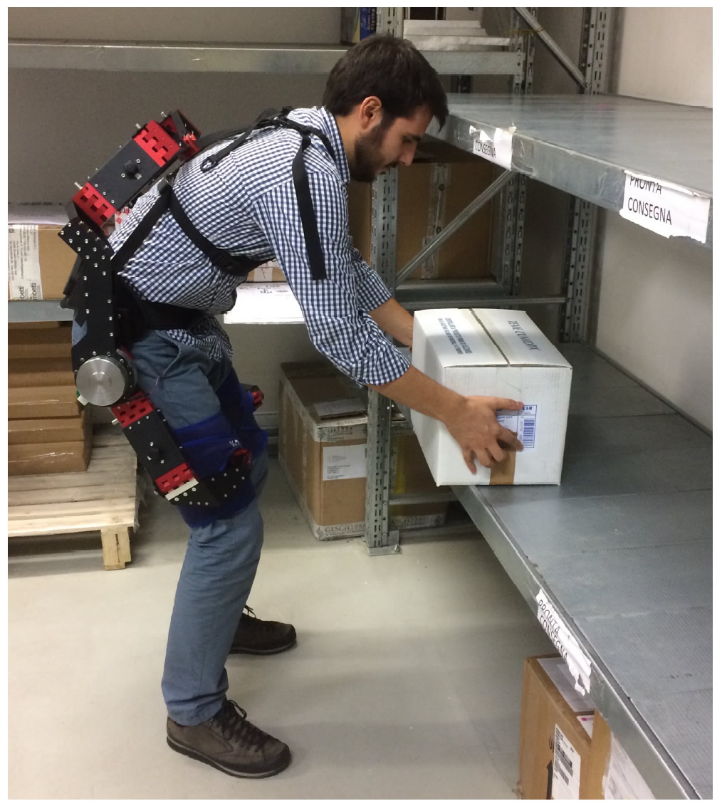
This paper presents an insole FSR (Force Sensing Resistor) to dynamically detect weight variations in an exoskeleton system. The proposed methodology is intended for tasks of lifting and lowering heavy weights with an industrial exoskeleton to substantially reduce spinal loads during these manual handling activities.
Instead of extensively placing high-dense force sensors by covering the whole plantar area, as most of commercial applications do, we integrate only a few force sensors in specific plantar area, so that the sensory system is not restricted to an individual foot size and shape, and on the other hand has relatively lower material cost.
Industrial exoskeletons are intended to assist workers when handling heavy goods. With this in mind, wearers are not able to use their hands to control the exoskeleton since they use them to handle the goods. Therefore, the exoskeleton controller is required to indirectly infer how much and when the wearer requires assistance for lifting or lowering a heavy weight. Our approach of dynamically detect and characterize the increment/decrement of weight, as well as the rising/falling edge, enables the exoskeleton’s controller to trigger the request of assistive force to the actuators.
I Introduction
It is a common practice in laboratory that the exoskeleton’s wearer controls the system by indirect measures, such as electromyography (EMG) [10, 11] or force/torque measurement generated from interaction [1][2]. This means that the wearer does not directly control the exoskeleton with a joystick as common cases for robots or mechanical systems. The reason behind is that the hands and in some cases the full body of the wearer are expected to be free. In this context, the ideal exoskeleton should be able to infer the intention of the user by indirect and reliable measures in which the user does not need to pay attention to control it, instead the wearer moves naturally as the system is able to follow the wearer movements like a ’shadow’.
EMG signals contain rich information that can be used to control and drive an exoskeleton robot and similar man-machine devices in both rehabilitation and assistance [21]. The wearable robot Hybrid Assistive Limb (HAL) developed by Sankai et al. [10], is comprised of four actuators for hip and knee assistance and uses feedback from both EMG and force sensors. Similarly, Li et al. [12] [11] and Fleischer et al. [6] [7] use EMG signals to control an exoskeleton.
However, in contrast to laboratory environments, where the temperature and humidity are controlled in an indoor setting, industrial environments present a big challenge for monitoring technologies that are glued or fasten to the operator’s body.
The robotic assistance of an industrial exoskeleton may alternatively be regulated according to external conditions, such as the weight of the object to be handled [13]. In this case, force sensors are integrated in the wearer’s footwear or within the plantar area of the exoskeleton where the wearer is standing on. Hence, from the force sensors it is possible to detect the variation of planar pressure which enables the exoskeleton’s controller to trigger the assistive force.
The plantar pressure systems available on the market, such as Ekso Bionics [4], Pedar [15] and F-Scan [5], embed high dense of force sensors to cover the complete plantar area in order to overcome the acceleration force. Due to the extensive coverage of the sensors, these systems are highly customized to the individual foot shape and size, priced over 15,000USD each. Thus, the applications purely depending on pressure measurement are limited to laboratory usage due to their high cost.
We intend to develop a sensory system, which is portable in common footwear and has low cost in material, so that it can be applied in industrial scenarios. We reduce the coverage of the sensors to only the heel and metatarsals area, where most of the foot pressure would be detected during upright standing position.
Our endeavor represents part of the Robo-Mate project [17], which aims to deliver a powerful exoskeleton, easy and intuitive to command. The goal of Robo-Mate is to develop a wearable powered device to substantially reduce spinal loads during lifting activities.
This paper is structured as follows: Section II describes the properties of common thin film force sensors and their applications in exoskeleton-foot sensors. Section III presents the concept and hardware prototype of the insole system with force sensors FSR to be integrated in the exoskeleton system. Section IV describes the circuit design for the insole FSR sensors. Section V presents the experimental results from the FSR and the algorithm to detect and characterize the lifting and lowering activities. Conclusions are proposed in Section VI, which also points at some of the next steps and future challenges expected in the future work.
II Force sensors
Initial attempts to have foot-force sensors to measure the pressure applied in the front and rear parts of the foot (ball and heel of foot) are described in [10]. Their proposed floor reaction force (FRF) sensor detects air pressure changes sensed when foot-pressure is applied to their customized air-pressure force sensors. Up to today the electrical force sensors instead of air pressure based sensors are widely applied. For instance, thin film sensors such as flexiforce (Tekscan®) or shunt force sensor (Sensitronics®) are ideal for integration in footwear, as they have small thickness of less than one millimeter to fit into the limited space of the footwear. In addition, these types of force sensors are an inexpensive and lightweight alternative to multi-axis force/torque sensors.
These types of force sensors have been integrated in biped robots for gait investigation[16], where they are placed on the bottom of the robot’s feet to provide feedback for the control system. Also, force sensors have been integrated inside shoes to monitor the foot pressure of a person when walking and running [3]. Moreover, in-pipe robots integrated these types of thin-film force sensors. For instance, the DeWaLoP in-pipe robot integrates six force sensors on each of its wheeled-legs to measure the force exerted when the robot extend the legs to become a rigid structure inside the pipe [14].
A force sensor can be modeled by Equation 1
| (1) |
where presents the received force by the sensor and presents the generated resistance based on given force, a constant is to model a smooth curve response.
Commercial force cells are commonly thick with heights of around and expensive, if compared to 6USD thin film force sensors with height of (). In our design we considered thin film force sensors, since these can be integrated under the shoe with the minimal height increment.
Commercial thin film force sensors have similar mechanical and electrical characteristics, which were analyzed in [16][18] and [8]. For our specific requirements, to dynamically detect the weight of a person when lifting or lowering a heavy object, we analyzed a couple of the most used commercial sensors: flexiforce and shunt force sensor. For our application we selected the shunt force sensor [19]. The key element for our selection is that the shunt force sensor provides relatively higher resolution in our use cases, from 0 to (), the sensor range is from 0 to ().
III Design
The intended sensorised insole system is integrated to the operator’s shoes which is able to dynamically measure weights and pressure changes when a person is lifting or lowering a heavy weight. The aim of the FSR insole system is to indirectly infer when the exoskeleton should assist the wearer and also to detect how much assistance is required.
To clearly differentiate the states of the operator, the force sensors located in the insole of the operator are required to have a good resolution, while physically being as thin as possible for not increasing the height of the operator.
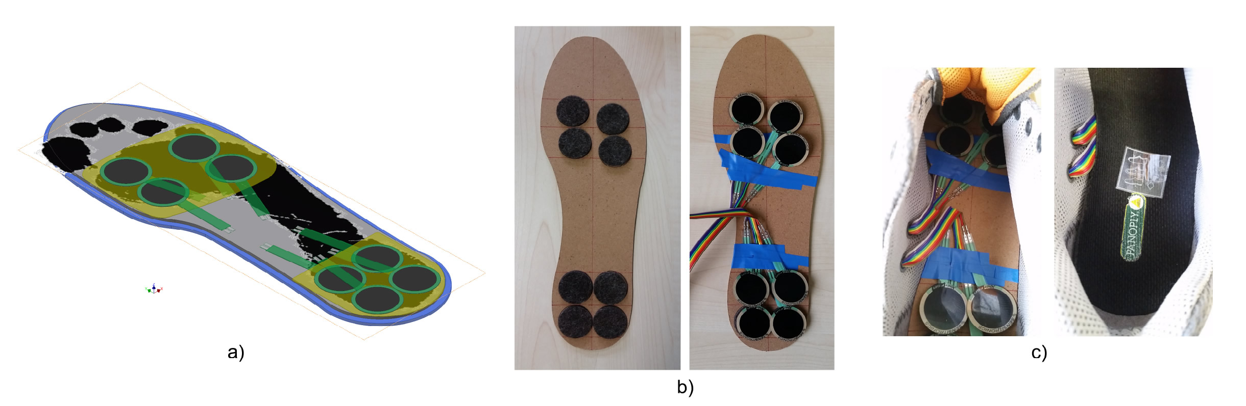
The proposed module design integrates eight force sensors per foot. They are divided into two groups of four sensors, located in the peak pressure points of a normal foot: the metatarsals and the heel [9]. In this configuration, the insole FSR system have a force resolution ranging from to if all the insole FSR sensors are at their maximum capacity. However, we are only considering a maximum of () per sensor, resulting in a maximum of ().
Each insole module consists of an inner base where the sensors are attached. The base is covered by the insole of the shoe to protect the sensors, see figure 2.
IV Force sensors calibration and equalization
Commercial thin film force sensors FSR have several drawbacks that make them not suitable for precise measurement of force. Their resistance response respect to the force is nonlinear and from sensor to sensor is different. This means that each sensor will respond with different resistance values even when the applied force is the same. Therefore, each thin film FSR sensor requires to be calibrated.
IV-A Force Sensor Calibration
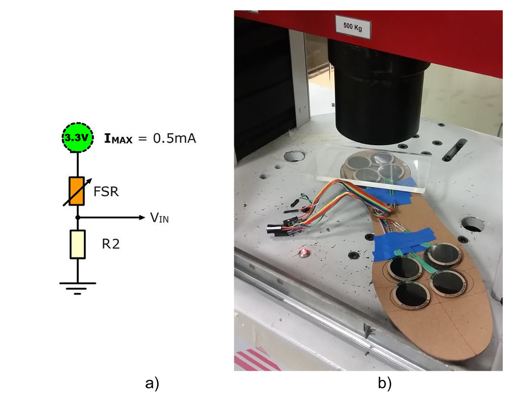
The FSR sensors integrate a conductive ink which have a maximum current limit. Figure 3 shows the circuit to protect and obtain the force-resistance curves from a FSR sensor.
The circuit consists of a voltage divisors. It is a current limiter to , which is the maximum current supported by the sensor [20], and it is also set to read the voltage at the FSR sensor. In this configuration, is calculated from the FSR resistance values, averaging the higher and lower limits to obtain a considerable ratio to differentiate between the levels, see Table I.
| Force level | R1 | R2 | Ratio | Vout |
| (in N) | (FSR sensor) | (Fixed) | R2/(R1+R2) | (in V) |
| (MAX) | 0.85 | 2.80V | ||
| 0.65 | 2.15V | |||
| (min) | 0.36 | 1.18V |
In order to calibrate the FSR sensors we used a compression test machine, see figure 3. We applied forces to each sensor in the range of 0 to (). We loaded the FSR sensor, applying the force in steps of () and holding for a couple of seconds, then release the force.
The voltage readings from the FSR sensor are converted to digital levels with an ADC (1024 steps of resolution). The voltage input , and the steps are calculated .
The resistance from a FSR sensor is obtained by Equation 2, where is the fix resistor in a voltage divisor configuration.
| (2) |
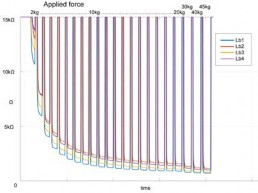
Once the sensors are calibrated, their force-resistance curves are know. These curves reveals that the sensors are considerably different, as shown in figure 4.
IV-B Sensor Configurations
The proposed insole design integrates eight force sensors per foot, making in total 16 force sensors. This means that ideally 16 input channels are required to monitor and process the sensors data from the feet.
Note: The FSR sensor cannot be group together in modules since they have different force-resistance curves. Even if the sensors are equalized, their responses are still different. Thus, the grouping of sensors will lead to erroneous results and we must take the value of each FSR sensor independently.
V Experiments
The objective of the experiments is to register the weight detected by the FSR sensors when all sensors are added independently, and also to detect and characterize the lifting and lowering activities.
V-A Experimental Setting
The experimental setting consists of four micro-controller boards, four radio transceiver and a computer to store and analyze the gathered data. In this setting, two Personal Area Networks (PAN) are created, one per foot. The aim of this setting is to enable the subject to move and walk naturally without cables between the computer and the insole FSR when performing the experiments.
V-B Experiment I
The experiments were performed in the insole configuration with 8 FSR sensors per foot.
Experiment I steps:
-
1.
Sensors are initialized (the person’s weight () is registered as weight).
-
2.
Repeat 3 times:
a) Walk few steps.
b) Lift up weight from the ground.
c) Lower weight from the ground.
Experiment II steps:
-
1.
Sensors are initialized (the person’s weight () is registered as weight).
-
2.
Walk few steps.
-
3.
Repeat 3 times:
a) Lift up weight from the ground.
b) Lower weight from the ground.
V-C Weight Detection Results
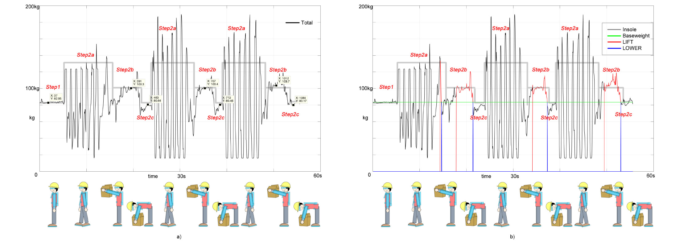
In Experiment I (see figure 5), the results show a correlation of the real applied force to the force read by the sensors. The weight of the subject is and the insole FSR sensors detected . When lifting the heavy object of the insole detected the weight . Also, when lowering the heavy weight during the repetitions, the insole system reads a similar weight
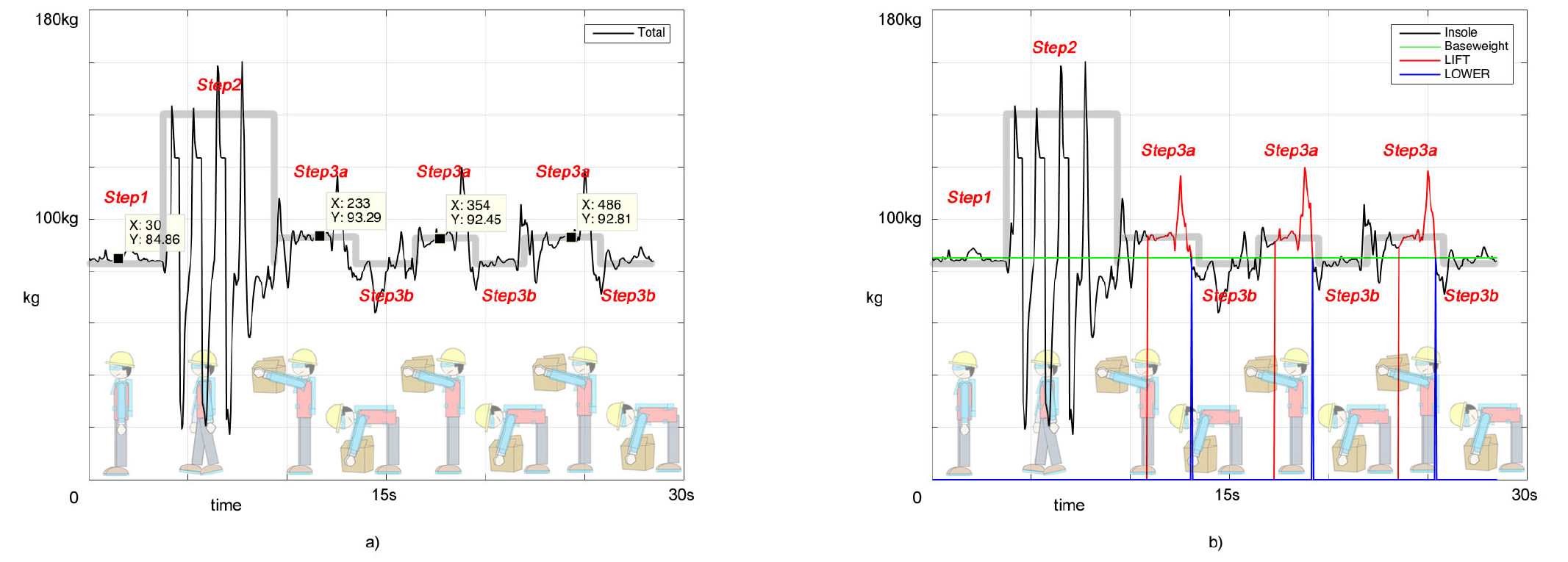
In Experiment II (see figure 6), the results are similar to Experiment I, the results show that the weight detected is consistent with the ground truth varying .
| Independent | Repetition 1 | Repetition 2 | Repetition 3 |
| configuration | (in ) | (in ) | (in ) |
| weight | |||
| lowering | |||
| percentage | |||
| lifting | |||
| weight detected | |||
| weight | |||
| percentage |
| Independent | Repetition 1 | Repetition 2 | Repetition 3 |
| configuration | (in ) | (in ) | (in ) |
| weight | |||
| lifting | |||
| weight detected | |||
| weight | |||
| percentage |
V-D Detection of Lifting and Lowering Activities
The detection of lifting and lowering are performed dynamically, this means that the sensors values require a quarter of a second to process and detect weight. In this context, the algorithm is based on weight detection over a time.
The lifting Algorithm 1, requires to know the user’s weight so it can be compared to the data read by the insole FSR sensors. From the experimental data, see figures 5 and 6, we know that the detected weight of the person goes lower its weight before a lifting. This is due to the dynamics of the bending movement of the person to pick an object from the ground. Thus, our algorithm sets a flag to prepare the lifting detection when this happens. Once the flag is set, the algorithm detects increments of weight over a time frame, in our case is one quarter of a second, to set the state of .
The lowering Algorithm 2, also requires to know the user’s weight so it can be compared to the data read by the insole FSR sensors. In the same way as the lifting detection, from the experimental data we know that before lowering the detected weight goes higher than the weight plus the lifted weight. This is due to the dynamics of the movements when the person is positioning to lower the heavy weight. In this way, our algorithm sets a flag to prepare the lowering detection. When the flag is set, the algorithm detects the decrement of weight and when it goes lower the weight then the algorithm set the state of .
Note: In Experiment I, see figure 5, the results show four lifting and lowering actions instead of three. However these detections are correct. At the beginning of the experiment, two packs of water bottles are pile one over the other and the user carries one pack with the right arm to put it on his right side to eventually carry one pack on each hand. In this link we collected the videos from these experiments111http://watsonjosh2.wix.com/insolefsr.
In Experiment II, see figure 6, the results clearly show the lifting and lowering of the heavy object.
VI Conclusion and future work
The results show that the proposed insole FSR system is able to detect the weight of a person and the lifted weight, by integrating force sensors located under the shoes of a person. The FSR insole system integrate 8 force sensors per foot, divided in two modules, one module located under the heel area and the other under the foot metatarsals. In this configuration, the FSR insole system is able to measure the forces between to . Nevertheless, it can measure a maximum of .
We computed the insole FSR sensors independently, since each sensor have a unique response and force-resistance curve. The results from adding the detected weight from all sensor are consistent to the ground truth with an average variation of .
Our proposed sensory system is portable to common foot wears or exoskeletons and nonrestrictive to individual foot due to its modularized sensor configuration instead of the classic configuration of one-piece extensively plantar coverage. On the other hand the FSR insole system has relatively low cost in production due to the minimum number of force sensors being integrated, so that it has the potential to be applied in industrial use.
Acknowledgment
The authors acknowledge the contributions of the entire Robo-Mate research consortium towards the creation of the Robo-Mate exoskeleton concept.
The research leading to these results has received funding from the European Union′s Seventh Framework Programme for research, technological development and demonstration under grant agreement n∘ 608979, and from the People Programme (Marie Curie Actions) of the European Union′s Seventh Framework Programme FP7/2007-2013/ for research, technological development and demonstration under REA grant agreement n∘ 608022.
References
- [1] G. Aguirre-Ollinger, J.E. Colgate, M.A. Peshkin, and A. Goswami. A 1-dof assistive exoskeleton with virtual negative damping: effects on the kinematic response of the lower limbs. In Intelligent Robots and Systems, 2007. IROS 2007. IEEE/RSJ International Conference on, pages 1938–1944, Oct 2007.
- [2] G. Aguirre-Ollinger, J.E. Colgate, M.A. Peshkin, and A. Goswami. Active-impedance control of a lower-limb assistive exoskeleton. In Rehabilitation Robotics, 2007. ICORR 2007. IEEE 10th International Conference on, pages 188–195, June 2007.
- [3] Joonbum Bae, Kyoungchul Kong, and M. Tomizuka. Design of a mobile gait monitoring system. In Advanced Intelligent Mechatronics (AIM), 2010 IEEE/ASME International Conference on, pages 1362–1367, July 2010.
- [4] EKSO. Ekso exoskeleton for rehabilitation, 2016-01-03, http://intl.eksobionics.com/ekso.
- [5] EKSO. Exoskeleton helping disabled to walk.?united press international, 6 january 2012., 2016-01-03, http://www.upi.com/.
- [6] C. Fleischer and G. Hommel. Calibration of an emg-based body model with six muscles to control a leg exoskeleton. In Robotics and Automation, 2007 IEEE International Conference on, pages 2514–2519, April 2007.
- [7] C. Fleischer and G. Hommel. A human–exoskeleton interface utilizing electromyography. Robotics, IEEE Transactions on, 24(4):872–882, Aug 2008.
- [8] Rick S. Hall, Geoffrey T. Desmoulin, and Theodore E. Milner. A technique for conditioning and calibrating force-sensing resistors for repeatable and reliable measurement of compressive force. Journal of Biomechanics, 41(16):3492 – 3495, 2008.
- [9] Tsung-Han Hsieh, An-Chih Tsai, Cha-Wei Chang, Ka-Hou Ho, Wei-Li Hsu, and Ta-Te Lin. A wearable walking monitoring system for gait analysis. In Engineering in Medicine and Biology Society (EMBC), 2012 Annual International Conference of the IEEE, pages 6772–6775, Aug 2012.
- [10] H. Kawamoto, Suwoong Lee, S. Kanbe, and Y. Sankai. Power assist method for hal-3 using emg-based feedback controller. In Systems, Man and Cybernetics, 2003. IEEE International Conference on, volume 2, pages 1648–1653 vol.2, Oct 2003.
- [11] Zhijun Li, Chun-Yi Su, Guanglin Li, and Hang Su. Fuzzy approximation-based adaptive backstepping control of an exoskeleton for human upper limbs. Fuzzy Systems, IEEE Transactions on, 23(3):555–566, June 2015.
- [12] Zhijun Li, Baocheng Wang, Fuchun Sun, Chenguang Yang, Qing Xie, and Weidong Zhang. semg-based joint force control for an upper-limb power-assist exoskeleton robot. Biomedical and Health Informatics, IEEE Journal of, 18(3):1043–1050, May 2014.
- [13] L. A. Mateos, J. Ortiz, S. Toxiri, J. Fernández, J. Masood, and D. G. Caldwell. Exoshoe: A sensory system to measure foot pressure in industrial exoskeleton. In 2016 6th IEEE International Conference on Biomedical Robotics and Biomechatronics (BioRob), pages 99–105, June 2016.
- [14] L.A. Mateos and M. Vincze. Lammos - latching mechanism based on motorized-screw for reconfigurable robots. In Advanced Robotics (ICAR), 2013 16th International Conference on, pages 1–8, Nov 2013.
- [15] PEDAR. Pedar, 2016-01-03, http://www.novel.de/novelcontent/pedar.
- [16] R. Pierce and G.S. Gupta. Investigation of force sensors for use in bipedal humanoid dynamic gait generation. In Sensors Applications Symposium (SAS), 2014 IEEE, pages 289–292, Feb 2014.
- [17] Robo-mate. Robo-mate - eu project, 2015-08-28, http://www.robo-mate.eu.
- [18] G. Sen Gupta, P. Barlow, and S. David. Review of sensors and sensor integration for the control of a humanoid robot. In Instrumentation and Measurement Technology Conference (I2MTC), 2011 IEEE, pages 1–5, May 2011.
- [19] Sensitronics. Force sensor - shunt-mode-fsr, 2015-08-28, http://www.sensitronics.com/products-1-inch-shunt-mode-fsr.php.
- [20] Sensitronics. Sensitronics shunt sensor 100lb, 2016-01-03, http://sensitronics.com/.
- [21] Hui Yan, R.P.S. Han, Yu Wang, and Jieru Chi. Controlling a powered exoskeleton system via electromyographic signals. In Robotics and Biomimetics (ROBIO), 2009 IEEE International Conference on, pages 349–353, Dec 2009.