The impact of the Hall effect during cloud core collapse: implications for circumstellar disk evolution
Abstract
We perform three-dimensional radiation non-ideal magnetohydrodynamics simulations and investigate the impact of the Hall effect on the angular momentum evolution in the collapsing cloud cores in which the magnetic field and angular momentum are misaligned with each other. We find that the Hall effect notably changes the magnetic torques in the pseudo-disk, and strengthens and weakens the magnetic braking in cores with an acute and obtuse relative angles between and , respectively. This suggests that the bimodal evolution of the disk size may occur in early disk evolutionary phase even if and are randomly distributed. We show that a counter-rotating envelope form in the upper envelope of the pseudo-disk in cloud cores with obtuse relative angles. We also find that a counter-rotating region forms at the midplane of the pseudo-disk in cloud cores with acute relative angles. The former and latter types of counter-rotating envelopes may be associated with the YSOs with a large ( AU) and small ( AU) disks, respectively.
1 Introduction
The evolution of angular momentum due to the magnetic field during cloud-core collapse has been a focal point in the research field of circumstellar disk formation and its early evolution in low mass star formation (Tomisaka, 2002; Price & Bate, 2007a; Mellon & Li, 2008; Commerçon et al., 2010; Machida et al., 2011a; Hennebelle & Fromang, 2008; Machida et al., 2014; Tomida et al., 2015; Tsukamoto et al., 2015a, b; Machida et al., 2016). The magnetic field connects inner (or central) and outer regions of the collapsing core, the former of which rotates faster than the latter, and efficiently transfers the angular momentum from the inner region to the outer region. This process is known as magnetic braking (Gillis et al., 1974; Mouschovias, 1985). Magnetic braking suppresses the formation of circumstellar disks, if the ionization degree of the gas is high enough and the ideal magnetohydrodynamics (MHD) approximation is applicable (Allen et al., 2003; Price & Bate, 2007b; Mellon & Li, 2008; Hennebelle & Fromang, 2008).
In real cloud cores, however, the ionization degree is very low and the gas has finite resistivity (e.g., Umebayashi & Nakano, 1990; Nishi et al., 1991; Nakano et al., 2002). In such partially ionized plasma, non-ideal MHD effects arise as correction terms in the induction equation. There are three non-ideal effects; Ohmic diffusion, Hall effect, and ambipolar diffusion. These non-ideal effects play crucial roles for formation and early evolution of circumstellar disks (see Tsukamoto, 2016, for a review).
Among these non-ideal effects, the Ohmic and ambipolar diffusions have been relatively well investigated (Machida et al., 2007, 2011b; Li et al., 2011; Tomida et al., 2013, 2015; Tsukamoto et al., 2015b; Masson et al., 2016). The Ohmic diffusion decouples the magnetic field from the gas at the density and the temperature K. The density roughly corresponds to that of the first core (Larson, 1969; Masunaga et al., 1998; Masunaga & Inutsuka, 1999; Vaytet et al., 2012; Vaytet & Haugbølle, 2017) and the Ohmic diffusion significantly reduces the magnetic braking efficiency in the first core. Several previous studies (Saigo & Tomisaka, 2006; Inutsuka et al., 2010; Tsukamoto & Machida, 2011; Machida & Matsumoto, 2011; Inutsuka, 2012; Tomida et al., 2015; Tsukamoto et al., 2015b) have pointed out that the first core is a precursor of a circumstellar disk. Thus, the suppression of the magnetic braking by the Ohmic diffusion in the first core enables circumstellar disk formation. The ambipolar diffusion has a similar effect on the disk formation. In the typically magnetized cloud cores, it becomes effective and decouples the gas from magnetic field at a slightly smaller density than the Ohmic diffusion, and the disk formation is further facilitated (Tsukamoto et al., 2015b; Tomida et al., 2015; Masson et al., 2016; Wurster et al., 2016).
The Hall effect introduces an interesting dynamics in the collapsing cloud core. The magnetic braking efficiency should depend on the relative direction of the magnetic field and angular momentum, if the Hall effect is properly taken into account (Wardle & Ng, 1999; Wardle, 2004; Krasnopolsky et al., 2011; Li et al., 2011; Braiding & Wardle, 2012a, b; Tsukamoto et al., 2015a; Wurster et al., 2016). When the magnetic field and angular momentum of the cloud core are parallel to each other, the Hall effect strengthens the magnetic braking. Conversely, when they are anti-parallel, it weakens the magnetic braking. Due to this property, the Hall effect possibly causes the bimodal disk-size evolution depending on the parallel or anti-parallel properties of the magnetic field and angular momentum of the cloud core (Tsukamoto et al., 2015a; Tsukamoto, 2016; Wurster et al., 2016). The envelope counter-rotating with respect to the disk forms in the anti-parallel cloud core (Krasnopolsky et al., 2011; Li et al., 2011; Tsukamoto et al., 2015a; Wurster et al., 2016). They have the size of several 100 AU and may be observable.
In all the previous studies about the Hall effect, the idealized cloud cores were assumed, in which the magnetic field and the angular momentum vector are either exactly parallel or exactly anti-parallel to each other. In real cloud cores, however, they are likely to be neither parallel nor anti-parallel, but be mutually misaligned. The misalignment may change the magnetic braking efficiency even without Hall effect (Matsumoto & Tomisaka, 2004; Hennebelle & Ciardi, 2009; Joos et al., 2012; Li et al., 2013; Lewis & Bate, 2017). Furthermore, the impact of the Hall effect depends on the direction of the poloidal field. The misalignment may provide a significant impact on the gas dynamics, once the Hall effect is incorporated in the simulation.
In this paper, we investigate the impact of the Hall effect in aligned and misaligned cloud cores. This paper is organized as follows. In §2, we briefly outline how the Hall effect affects the angular momentum evolution in collapsing cloud cores. In §3, we describe the numerical methods and models used in this study. §4 is the main part of this paper and describes the results of the simulations. Finally, the results are summarized and discussed in §5.
2 Impact of Hall effect in collapsing cloud cores
The Hall effect generates toroidal magnetic field from poloidal magnetic field in the collapsing cloud core and changes the efficiency of the magnetic braking. It is a unique feature of the Hall effect. In this section, we briefly review how the Hall effect affects the angular momentum evolution during the cloud collapse.
To clarify how the Hall effect affects the magnetic field, we rewrite the induction equation with the Hall effect as,
| (1) | |||||
where , , , and are the gas velocity, the resistivity for the Hall effect, the magnetic field, and the unit directional vector of the magnetic field, respectively. is the drift velocity induced by the Hall effect and is defined as,
| (2) |
where is the speed of light and is the electric current. These equations clearly indicates that the Hall effect drifts the magnetic field toward the direction of .
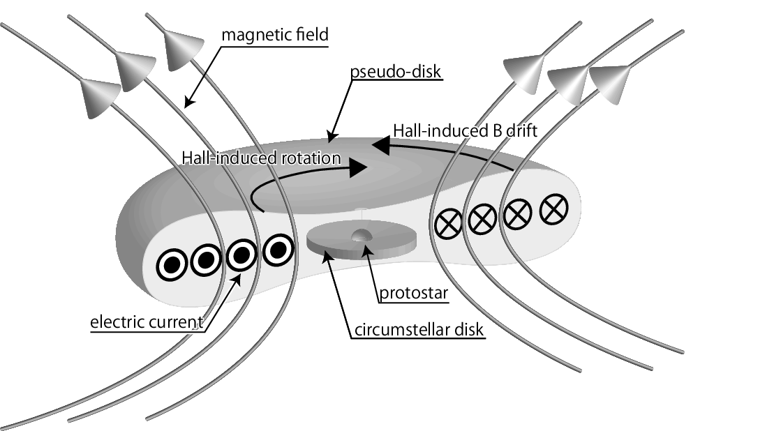
Figure 1 shows the schematic diagram of the central structure of a collapsing cloud core. During the gravitational collapse, the magnetic field is dragged toward the center and an hourglass-shaped magnetic field structure is formed. At the “neck” of the hourglass of the magnetic field, a toroidal current exists. As the magnetic field is inwardly dragged and amplified, the Lorentz force deflects the moving gas toward the direction parallel to the magnetic field, and accordingly the gas moves to the equatorial plane. As a result, a flattened disk-like structure, so called pseudo-disk, is formed at the neck of the hourglass of the magnetic field where a toroidal current sheet exists. Because is parallel to , the Hall effect drags the magnetic field to the azimuthal direction as if the gas rotates with the velocity in the pseudo-disk. The generated toroidal magnetic field exerts a toroidal magnetic tension on the gas in the pseudo-disk and changes its angular momentum. In other words, the Hall effect induces the gas rotation even if the cloud core was not rotating initially. Since the direction of the induced rotation is opposite to , it is right- and left-handed screw directions of the poloidal magnetic field when and , respectively (see equation (2)). In the cloud cores, is satisfied in the almost entire region (Tsukamoto et al., 2015a; Marchand et al., 2016; Wurster, 2016). Thus, with the Hall effect, the magnetic braking is strengthened in parallel cloud cores in which mutual angle is and weakened in anti-parallel cloud cores in which mutual angle is . In the misaligned cloud cores, it is expected that the Hall effect induces the rotation with the left-handed screw direction of the global poloidal field of the pseudo-disk and indeed will be confirmed in §4.
| Model name | Relative angle | With Hall effect |
| Model0 | Yes | |
| Model45 | Yes | |
| Model70 | Yes | |
| Model90 | Yes | |
| Model110 | Yes | |
| Model135 | Yes | |
| Model180 | Yes | |
| Model0NoHall | No | |
| Model45NoHall | No | |
| Model70NoHall | No | |
| Model90NoHall | No |
3 Numerical Method and Initial Conditions
3.1 Numerical Method
In our simulations, the non-ideal radiation magneto-hydrodynamics equations with self gravity are solved,
| (3) | |||||
| (4) | |||||
| (5) | |||||
| (6) | |||||
| (7) |
Here, is the gas density, is the gas pressure, and are the resistivities for the Ohmic and ambipolar diffusions, respectively, is the radiation energy, is the radiation flux, is the radiation pressure, is the gas temperature, is the Plank mean opacity, is the total energy where is the specific internal energy, and is the gravitational potential. The parameters and are the radiation and gravitational constants, respectively.
To close the equations for radiation transfer, we employ the flux-limited diffusion (FLD) approximation,
where is the Rosseland mean opacity.
We use the smoothed particle hydrodynamics (SPH) method (Monaghan & Lattanzio, 1985; Monaghan, 1992) in our simulations. The numerical code has been developed by the authors and been used in our previous studies (e.g., Tsukamoto & Machida, 2011, 2013; Tsukamoto et al., 2013b, 2015c). The ideal MHD part was solved with the Godunov smoothed particle magnetohydrodynamics (GSPMHD) method (Iwasaki & Inutsuka, 2011). The divergence-free condition is maintained with the hyperbolic divergence cleaning method for GSPMHD (Iwasaki & Inutsuka, 2013). The radiative transfer is implicitly solved with the method of Whitehouse & Bate (2004) and Whitehouse et al. (2005). We treated the Ohmic and ambipolar diffusions with the methods described in Tsukamoto et al. (2013a) and Wurster et al. (2014), respectively. Both the diffusion processes were accelerated by super-time stepping (STS) (Alexiades et al., 1996). For the Hall effect, we used the method described in Wurster et al. (2016). To calculate the self-gravity, we adopted the Barnes-Hut tree algorithm with opening angle of (Barnes & Hut, 1986). The dust opacity and gas opacity tables were obtained from Semenov et al. (2003) and Ferguson et al. (2005), respectively. We adopted the tabulated equation of state (EOS) table used in Tomida et al. (2013), in which the internal degrees of freedom and chemical reactions of seven species are included. The resistivity model is the same as in our previous studies (Tsukamoto et al., 2015a, b).
3.2 Initial and boundary conditions
We model an initial cloud core as an isothermal uniform gas sphere. The mass and temperature of the initial core are set to be 1 and 10 K, respectively. The radius of the core is AU, and the initial density is . The core is assumed to be rigidly rotating with an angular velocity of . The rotation energy normalized by the gravitational energy of the initial core is . The initial angular momentum vector is parallel to the -axis. The initial magnetic field has a magnitude of . The corresponding initial mass-to-flux ratio relative to the critical value is , where and (Mouschovias & Spitzer, 1976). The initial magnetic field is uniform and tilted on the - plane and given by
| (8) |
The mutual angle between the magnetic field and angular momentum is the primary parameter of interest in this paper. The model names and are listed in Table 1. The initial cores are modeled with about SPH particles. We also perform simulations without the Hall effect for comparison. We conduct the simulations until the epoch immediately after the protostar formation (the central density becomes ).
The boundary condition is set so that the particles with for rotate with the initial angular velocity . Thus, the gas is confined in a rigidly rotating shell. Both the magnetic field and the velocity field rotate with the shell. This boundary condition is similar to that used in Matsumoto & Tomisaka (2004); Machida et al. (2007) and was also used in our previous studies (Tsukamoto et al., 2015a, b). At the boundary, the magnetic field is assumed to be frozen-in to the gas because ideal MHD approximation is valid in the free-fall time scale at the initial density (Nakano et al., 2002). In addition, a boundary condition for radiative transfer is introduced in which both the gas and radiation temperatures are fixed to be 10 K at .
4 Results
4.1 Central structures
We investigate two-dimensional density cross-sections to study the central structures formed in the simulations. The issues which are discussed in subsequent subsections are introduced in this subsection.
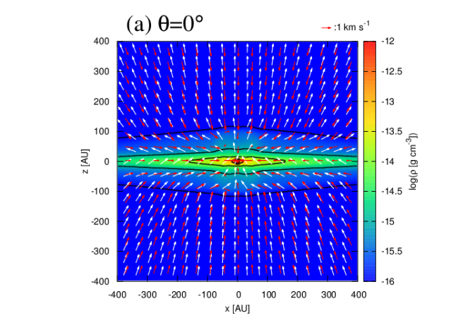
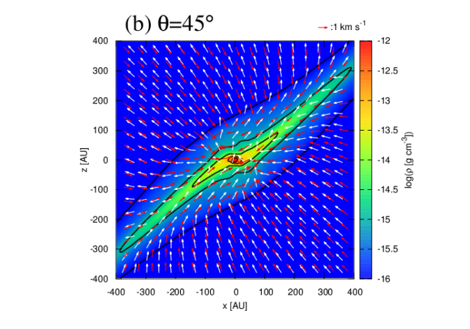
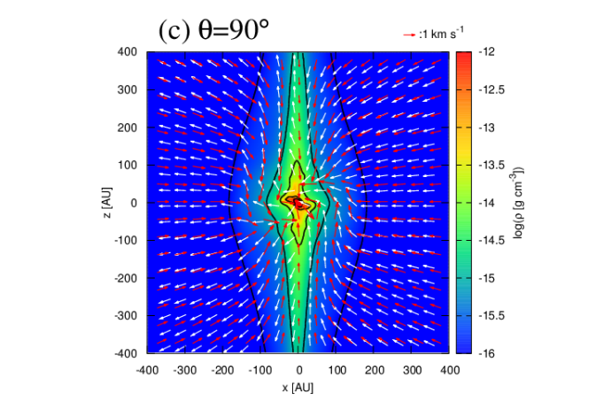
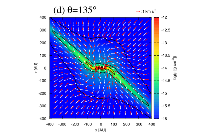
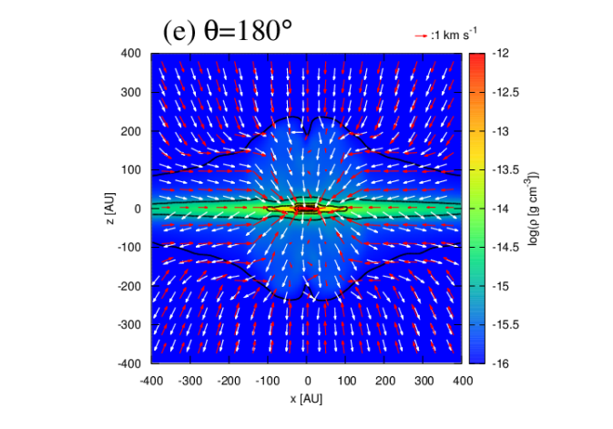
Figure 2 shows the density cross-sections on the - plane for the central -AU square region at the end epoch of the simulations. A notable structure in this spatial scale is a pseudo-disk (Galli & Shu, 1993), which is morphologically identified as a flattened disk-like structure with a scale of AU. In our simulation, the region corresponds broadly to the green region and its density is (see, also the contours). The gas velocity found to be almost parallel to the magnetic field in the upper envelope of the pseudo-disk; it must be because the Lorentz force deflects the gas motion toward the magnetic field direction. The white arrows in the figure clearly show that the magnetic field has the hourglass-shape structure and that the pseudo-disk resides at the neck of the hourglass. It is consistent with the expected configuration (figure 1), and implies that the current sheet exists at the midplane of the pseudo-disk. The polar angle of the pseudo-disk normal is approximately equal to the relative angle (see section 4.3 for the definition of the pseudo-disk normal). As discussed later, however, this does not mean that the pseudo-disk normal is parallel to the initial magnetic field direction, because the azimuthal angle is different between them.
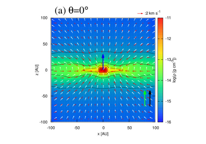
In our simulation, outflows are formed in Model0 and Model180 although they are very weak and are barely recognized in the panels (a) and (e) in which the gas in and AU weakly outflows. It is consistent with the previous studies. Tsukamoto et al. (2015b) and Masson et al. (2016) argued that the magnetic diffusions weaken the outflow or even suppress the formation of the outflow in the very early phase of protostar formation. By contrast, the previous studies with the ideal MHD simulations reported that the outflow forms in the very early stage of the protostar formation (e.g., Tomisaka, 2002; Matsumoto & Tomisaka, 2004; Hennebelle & Fromang, 2008; Machida et al., 2004; Tsukamoto et al., 2015b; Tomida et al., 2015; Masson et al., 2016). The difference may be mainly due to the saturation of the magnetic field strength caused by the ambipolar diffusion. The resistivity of the ambipolar diffusion is proportional to the square of the magnetic field strength as . As the magnetic field is amplified by the gas motion, increases and the ambipolar diffusion increasingly prevents further amplification of the magnetic field strength. This would introduce an upper limit for the magnetic field strength as discussed in Masson et al. (2016). This saturation may suppress the outflow formation. We investigate this in detail in §4.6.
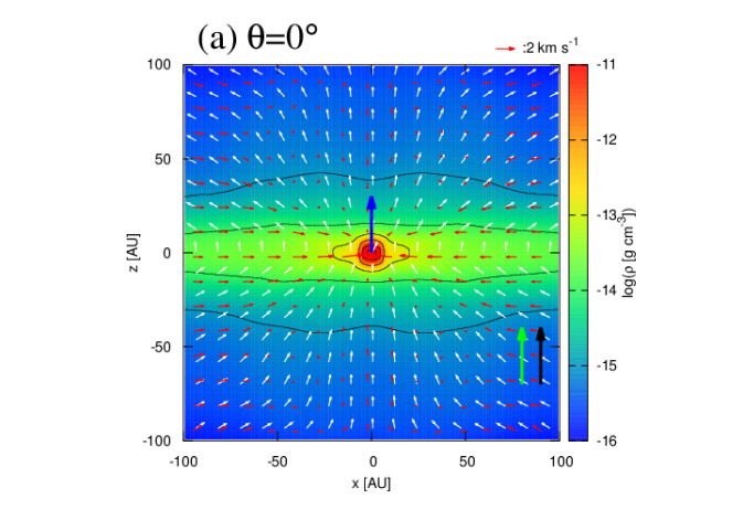
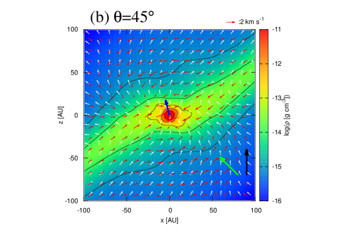
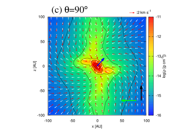
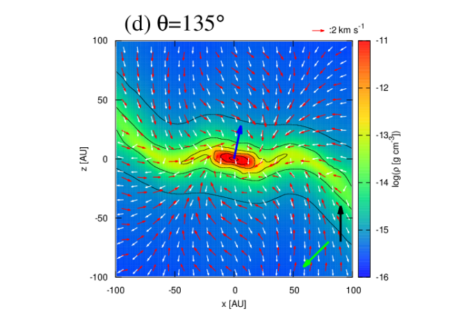
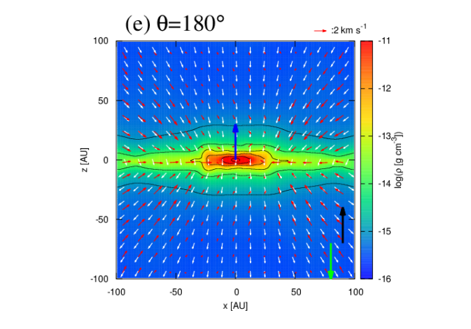
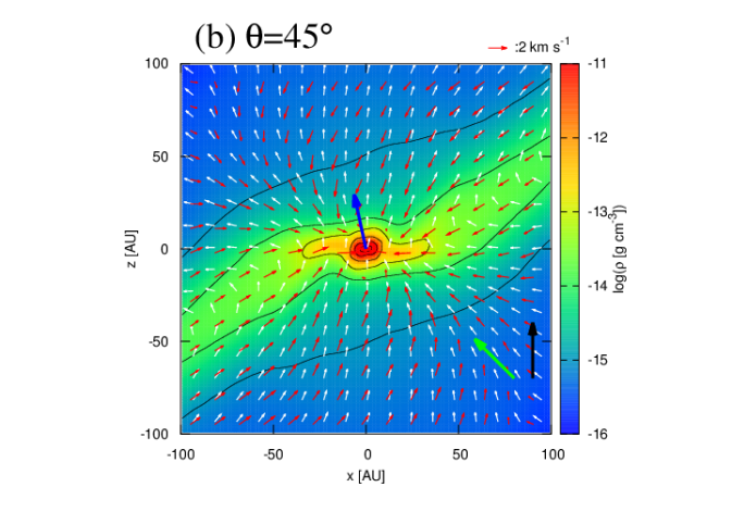
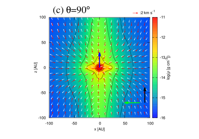
Figure 3 shows the density cross-section for the central -AU square region at the end of the simulations which is the zoom-in of figure 2. By comparing the central structures of Model0 (panel (a)) and Model180 (panel (e)), or Model45 (panel (b)) and Model135 (panel (d)), we find that the dense regions () in the core with obtuse angles (, hereafter referred to as “obtuse-angle cores”) are more flattened and extended than those in the cores with acute angles (, hereafter “acute-angle cores”). This difference is caused by the difference in the rotation strengths at the central dense regions. The obtuse-angle cores have larger central angular momentum. We will further discuss the difference of the angular momenta among the models in §4.2.
The blue arrow at the center of each panel in figure 3 shows the direction of the mean specific angular momentum of the region with , which is calculated by
| (9) |
where
| (10) |
by substituting . The vector length of on the panels normalized to be AU and is projected on the - plane. Thus, the shorter vector length indicates that is tilted toward the -axis. Apart from Model0 and Model180, the direction of the angular momentum of the central region is parallel to neither the initial angular momentum (its direction is shown by the black arrow in each panel) nor the initial magnetic field (green arrow) because it is affected both by the initial angular momentum and Hall-induced angular momentum whose direction roughly corresponds to the normal direction of the pseudo-disk.
What changes does the Hall effect make in the central structures? We show in figure 4 the density cross-section on the - plane of the models of Model0NoHall, Model45NoHall, Model90NoHall, all of which are the models without the Hall effect. The difference is particularly prominent between Model90 (figure 3c) and Model90NoHall (figure 4c). In the density cross-section with Model90NoHall, the density structure has line-symmetry along the -axis, whereas with Model90, the central density and magnetic field structures are distorted. The direction of the central angular momentum in Model90NoHall is parallel to the initial angular momentum (i.e., the -axis), whereas that in Model90 is not and is tilted toward the -axis.
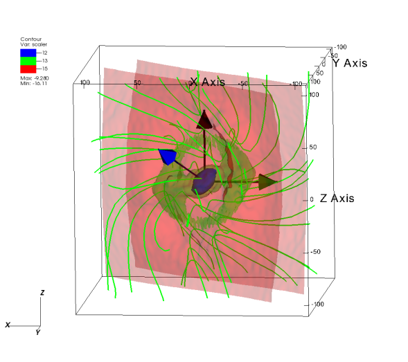
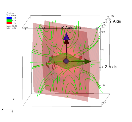
To investigate further the structures with Model90 and Model90NoHall, we show figure 5, the three-dimensional structures of the central regions of Model90 and Model90NoHall. The isodensity surfaces are identical to those of the contours in figures 2 and 3. Among these, the red surface traces the pseudo-disk (see figure 2). Due to the initial core rotation, the large-scale magnetic field rotates around the -axis and the pseudo-disk normal is not parallel to the initial magnetic field direction.
In Model90, the magnetic field (in green lines) is helically twisted in the right-handed screw direction of the poloidal magnetic field. In Model90NoHall, by contrast, the helical structure does not appear, and the magnetic field is roughly axisymmetric about the pseudo-disk normal. The magnetic tension induced by the helical structure prompts the gas to rotate around the midplane of the pseudo-disk. As a result, the central structure () in Model90 becomes distorted and gains the angular momentum of which the direction (indicated by the blue arrow) is parallel to neither that of the initial angular momentum (indicated by the black arrow) nor the initial magnetic field (indicated by the green arrow). In Model90NoHall, the angular momentum direction of the central dense region, by contrast, is parallel to the initial angular momentum (see blue and black arrows). The direction of the angular momentum is further investigated in §4.5.
4.2 Difference in angular momentum distribution
In our previous study (Tsukamoto et al., 2015a), we suggested that the Hall effect would introduce the bimodal evolution of the disk size (or the central angular momentum) depending on the parallel or anti-parallel properties of the angular momentum and the magnetic field in the initial cloud cores. However, the cases considered in the study were only those of and . An important unsolved question is whether the Hall-induced bimodal evolution is still expected even when the magnetic field and the angular momentum vector are misaligned. To answer it, we investigate the absolute values of angular momentum in the models.
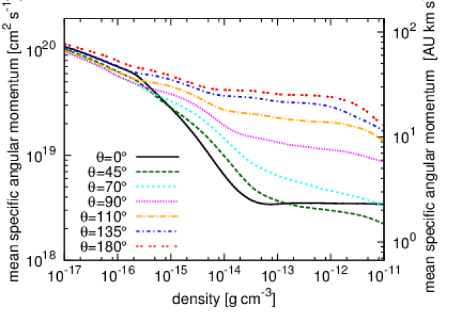
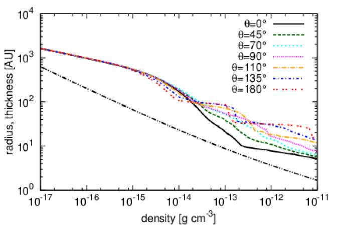
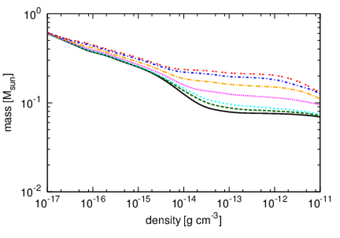
Figure 6 shows the mean specific angular momentum (equation (9)) as a function of the density at the end of the simulations. To grasp the characteristic scales at a density, We show the characteristic radius, the characteristic thickness, and the enclosed mass as a function of the density in figure 7. The characteristic radius is defined as maximum distance from the center among the SPH particles which satisfy where is the particle density. The characteristic thickness is defined as the scale-height of the self-gravitating sheet, where we assume that for simplicity. The enclosed mass is defined by the equation (10).
Figure 6 shows that, at , which roughly corresponds to the mean specific angular momentum of the central dense structure shown by the red region in figure 3 (the radii and enclosed mass at this density are several AU and , respectively), the angular momenta in Model0 and Model180 differ by an order of magnitude. The magnetic torques induced by the Hall effect in the case of and have the opposite and same directions of/as the initial angular momentum of the core, and the Hall effect strengthens and weakens the magnetic braking, respectively. As a result, the specific angular momentum are minimum and maximum in Model0 and Model180, respectively.
By comparing the results of the Model0 (black line) and Model45 (green line), or Model180 (red line) and Model135 (blue line) at , we can see that the misalignment from parallel or anti-parallel configuration introduces only a very small difference in the central angular momenta. This suggests that a small degree misalignment such as hardly changes the angular momentum evolution. Furthermore, even the differences between Model0 and Model70 with considerable amount of misalignment, and that between Model180 and Model110 remains within a factor of two at and are still only moderate. Therefore, the Hall-induced bimodal evolution for the disk size is expected even when the magnetic field and the angular momentum vector are randomly distributed.
The difference among any of the models for the density region (at the radii of AU) is found to be within a factor of two and small, whereas a large difference is introduced in or at the radius of AU. The latter density and radius range correspond to that of the pseudo-disk (see the contours in figure 2). This suggests that the Hall effect is not effective in and mainly influences the specific angular momentum of the pseudo-disk.
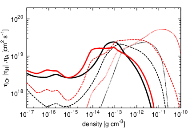
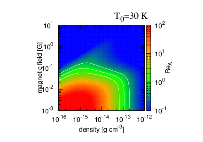
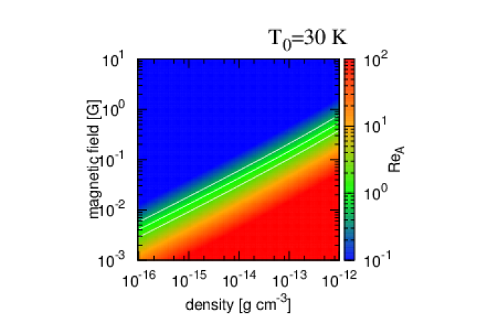
Why does the Hall effect become effective in the pseudo-disk ? The pseudo-disk forms at the “neck” of the hourglass structure where the toroidal current exists (figure 2). The Hall effect drags the magnetic field toward the direction of the electric current and the field drift velocity is proportional to the intensity of the current (equation (2)). Furthermore, in our resistivity model, is larger than and in the density range of the pseudo-disk. Figure 8 shows the volume average value of the magnetic resistivity given by
| (11) |
where
| (12) |
as a function of the density. We find that the is higher than and for and that the Hall effect dominates the other non-ideal MHD effects in the pseudo-disk. Note that the difference in comes from the difference in the density structures around the center. These two factors explain why the Hall effect significantly changes the magnetic torque in the pseudo-disk.
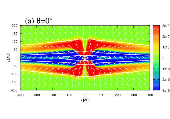
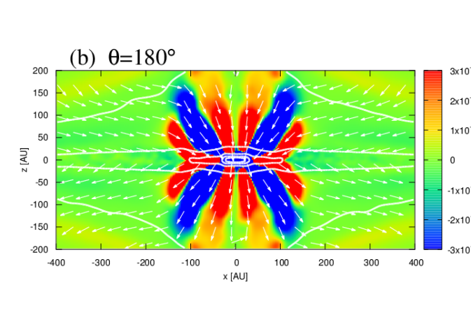
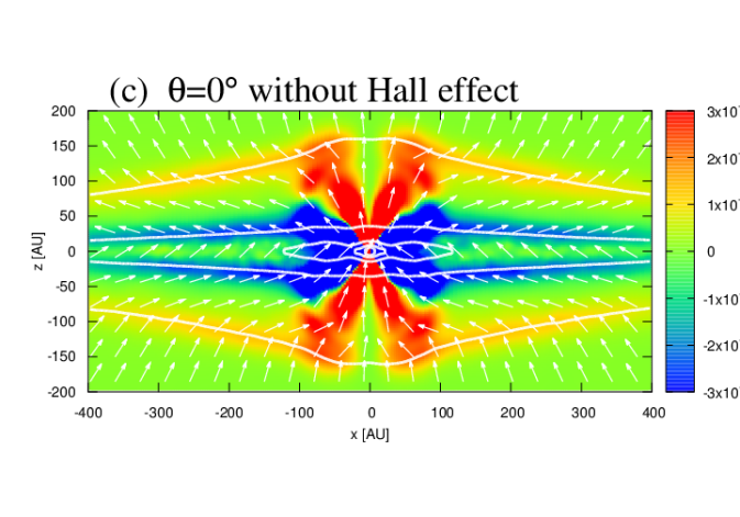
Figure 9 shows the -component of the torque exerted by the Lorentz force for Model0, Model180, and Model0NoHall. In model0, the negative magnetic torque is exerted in the almost entire region of the pseudo-disk (panel (a)). In model180 (panel (b)), the magnetic torque in the pseudo-disk is significantly weaker than in Model0, because the toroidal magnetic field induced by the gas rotation is canceled by the Hall-induced toroidal field. Interestingly, at AU in the midplane of the pseudo-disk in Model180, there exist regions where the magnetic torque is positive (red-colored region in figure 9). In these regions, the Hall-induced toroidal magnetic field is much larger than that induced by the gas motion, and the magnetic torque exerts the positive angular momentum. For reference, the strength of the magnetic torque without the Hall effect (Model0NoHall; panel (c)) is in between Model0 and Model180, as expected. From the results discussed above, we conclude that the difference in the magnetic torques in the pseudo-disk causes the differences in the specific angular momenta which is apparent in figure 6.
4.3 Counter-rotating envelopes in obtuse-angle cloud cores
In our previous paper (Tsukamoto et al., 2015a), we showed that the counter-rotating envelopes against disk rotation form in a core with the anti-parallel configuration between the magnetic field and angular momentum, and suggested that the counter-rotating envelope would be observable. In the anti-parallel cloud cores, the toroidal magnetic field running in the opposite direction to that of the gas rotation is induced by the Hall effect, and as a result, the magnetic braking is weakened. Furthermore, the magnetic torque can become positive and enhance the rotation (“magnetic acceleration”), as we have demonstrated in the previous subsection. Because of the angular momentum conservation, the negative angular momentum is transferred upper region of the pseudo-disk. As a result, the gas in the upper envelopes spins down, and eventually counter-rotating envelopes form. The counter-rotating envelopes have been demonstrated to appear in many published studies that investigated the impact of the Hall effect (Krasnopolsky et al., 2011; Li et al., 2011; Tsukamoto et al., 2015a; Wurster et al., 2016) with multi-dimensional simulations in spite of the fact that they employed different numerical codes, initial conditions, and resistivity tables from one another. Thus, one may argue that their formation is a theoretically established prediction.
However, all the previous studies have assumed the parallel or anti-parallel configuration in their simulations, and therefore it is still unclear whether counter-rotating envelopes also appear even in the misaligned cores. If a counter-rotating envelope forms only in the aligned configuration or close, the likelihood of the emergence of counter-rotating envelope is small and so is our chance to observe one. Here, we investigate the misaligned case in detail. Hereafter, we refer to the counter-rotating regions against the central rotation (within AU) as “counter-rotation”.
Visualizing the counter-rotating envelope with the misaligned configuration is not a straightforward task. The angular momentum vector of the Hall-induced rotation is roughly parallel to the normal of the pseudo-disk. Thus, the angular momentum vector of a counter-rotating envelope is expected to be also parallel to the normal of the pseudo-disk and is not in any of the -, -, and - planes in the models with (see figure 5 for example). Hence, we should choose the plane in which the normal vector of the pseudo-disk lies to visualize the counter-rotating envelopes in the misaligned cloud core with a two-dimensional cross-section.
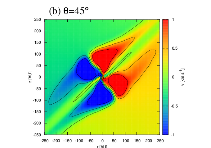
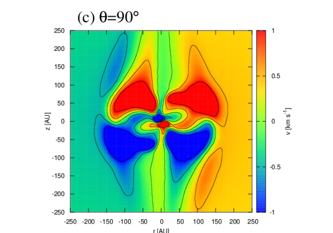
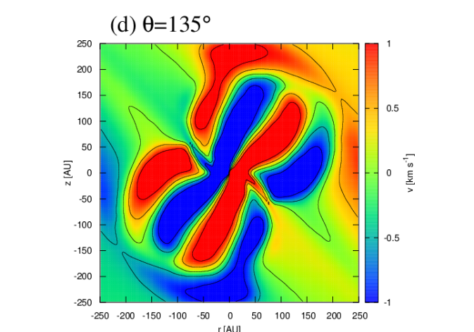
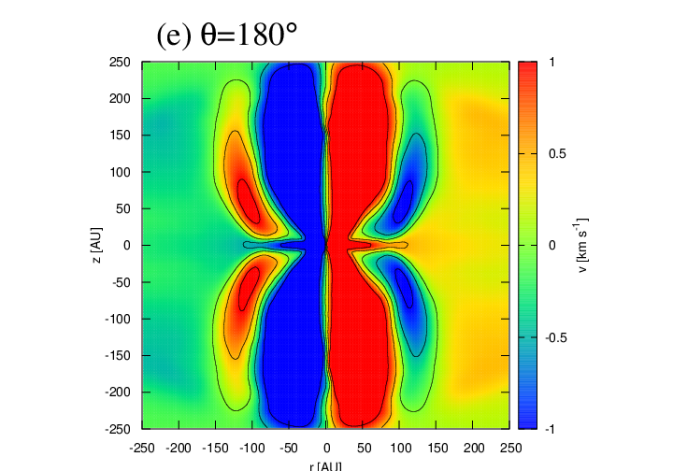
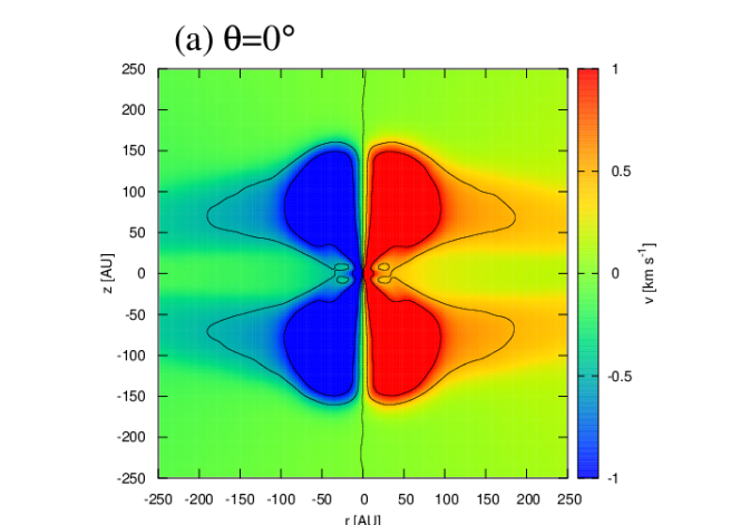
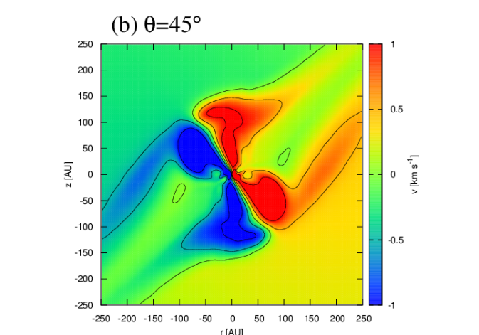
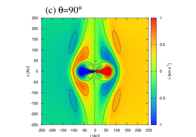
In figure 10, we show the cross-section of rotation velocity on the plane of which the normal vector is given by
| (13) |
where corresponds to the direction of the initial angular momentum and is the normal vector of the pseudo-disk. The vector is defined as the eigen vector corresponding to the minimum eigen value of the moment of inertia of the pseudo-disk, which is calculated by
| (14) |
where the pseudo-disk density of is assumed (see figure 2). In the figure, we choose the basis vectors of the cross-section plane as and , and the coordinate vector is defined with respect to the basis. The rotation velocity is defined as
| (15) |
and the direction of (and, hence ) is chosen so that positive and negative rotation velocities are realized in and , respectively, when the initial angular momentum is conserved. In addition, figure 11 shows the results without the Hall effect for comparison.
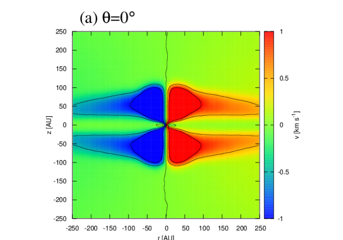
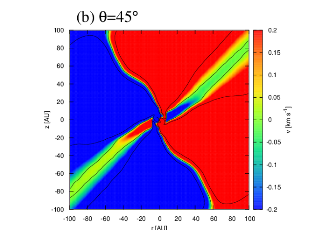
We find that the counter-rotating envelopes form at the upper region of the pseudo-disk (at AU) in Model180 (panel (e) of figure 10). The scale of the counter-rotation is AU. Note that the counter-rotating region corresponds to the region where the torque exerted by the Lorenz force is negative (panel (b) of figure 9). We should also note that the difference between panel (e) and figure 5 of Tsukamoto et al. (2015a) is originated from the difference in the epochs and the result shown in panel (e) is more evolved. The panel (d) (Model135) shows that a counter-rotating envelope also forms even in the misaligned cloud core. Its morphology is similar to that in Model180 but is tilted about from the -axis and parallel to the normal direction of the pseudo-disk, as we have expected. Interestingly, even in the core in the perpendicular configuration (Model90; panel (c)), a counter-rotating envelope against the central rotation forms. The panel clearly shows that counter rotation occurs around the the pseudo-disk normal. Although a counter-rotating region appears also in Model90NoHall as shown in the panel (c) of figure 11, the structure and strength of the counter-rotation is clearly different in the simulation with Hall effect (panels (c) of figure 10 and 11).
In the Model0 and Model45 (panel (a) and (b) of figure 10), the counter-rotating envelope does not appear, because the Hall-induced rotation at the midplane has the opposite direction of the initial rotation and its back-reaction has the same direction as the initial rotation. The velocity structures shown in those panels are very similar to those in the simulations without the Hall effect (Model0NoHall and Model45NoHall; panel (a) and (b) of figure 11).
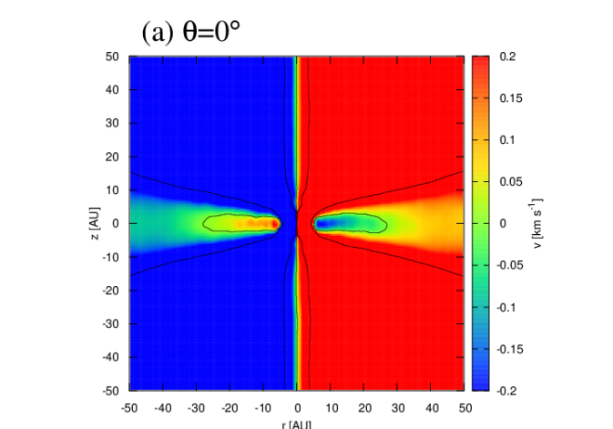
4.4 Another type of counter rotation in acute-angle cloud cores
The counter-rotating envelope discussed in the previous subsection is caused by the back-reaction of the rotation enhancement at the midplane of the pseudo-disk and is formed in obtuse-angle cores. In this subsection, we investigate another mechanism that can trigger counter-rotation in acute-angle cores. Contrary to the cases in obtuse-angle cores, the Hall effect strengthens the magnetic tension against rotation at the midplane of the pseudo-disk (see figure 9). Unlike the ordinary magnetic braking in which the toroidal field is induced by the gas rotation, the negative torque is exerted on the gas by the Hall effect even when the gas rotation velocity becomes zero because the toroidal field is induced by the electric current. As a result, the gas can begin to counter-rotate at the midplane of the pseudo-disk.
Figure 12 shows the zoom-in cross-section of the rotation velocity in Model0 (panel (a)) and Model45 (panel (b)) in the central region on the plane defined by the normal vector of equation (13). Both the panels reveal that there are regions where the gas rotates in the opposite direction to the initial rotation. The size and the velocity of the regions are AU to AU and , respectively. Both the values are smaller than those in the counter-rotating envelopes discussed in §4.3. The counter-rotating region in Model45 is more extended than that in Model0. We confirm that the counter-rotating region around the midplane of the pseudo-disk does not form in the simulations without the Hall effect. Therefore, the Hall effect plays a crucial role for the formation of these structures.
Although the counter-rotating regions are small, they are potentially detectable in future high-resolution observation of YSOs. A counter-rotating structure may appear on the perpendicular direction of the outflow as a small (negative) velocity component () at 10 to 100 AU scale. Because the angular momentum of the central region in the acute-angle cores is small (figure 6), YSOs which do not have a large disk, such as B335 (Yen et al., 2015), would be a candidate to observe this kind of counter-rotating structures.
This kind of counter-rotation in the pseudo-disk also potentially plays an important role in the subsequent evolution. Counter-rotating regions are connected to the remnant of the first core or the new-born disk. If the mass accretion onto the disk occurs mainly from counter-rotating regions, and if the total angular momentum flux toward the central region becomes negative, the disk rotation may flip during the subsequent accretion phase. The negative angular momentum flux to the disk can cause various dynamical phenomena such as gap opening (Vorobyov et al., 2015, 2016). In these previous studies, the inversely rotating outer region is assumed in the initial cloud core and its generality in the real cloud core is unclear. Alternatively, the Hall effect provides a mechanism to cause the inversely rotating accretion flows.
4.5 Direction of the angular momentum
The direction of the angular momentum of the central region is influenced by the Hall effect (figure 3). The direction of the central angular momentum determines the direction of the circumstellar disk and that of the outflow in the subsequent evolution and hence is an important parameter. We investigate it in detail in this subsection.
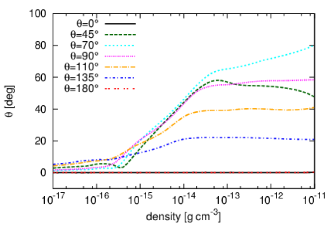
Figure 13 shows the polar angle of the mean angular momentum as a function of the density , as given by
| (16) |
where and are the and components of . In this formula, indicates that is parallel to the initial angular momentum. We find that, in the low-density region , the polar angle is and the mean angular momentum is parallel to the initial angular momentum as expected. The polar angle begins to increase at , which corresponds to the density range of the pseudo-disk; it means that the mean angular momentum begins to tilt from the -axis in the pseudo-disk. Again, this confirms that the Hall effect mainly influences the angular momentum in the pseudo-disk.
Comparing the in Model45 (magenta line) and Model135 (green line) or in Model70 and Model110 for , we find that is larger in acute-angle cores than in obtuse-angle cores. This can be explained as follows. The Hall-induced rotation has a left-handed screw direction of the global poloidal field of the pseudo-disk (again here we assume ), and the Hall-induced angular momentum has the opposite direction to the global poloidal field. Thus, the mutual angle between the Hall-induced angular momentum and initial angular momentum is obtuse in acute-angle cores and is acute in obtuse-angle cores.
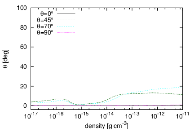
To confirm that a large is induced by the Hall effect, we calculate in the models without the Hall effect and plot it in figure 14. The figure shows that the mean angular momentum have a non-zero in the misaligned models even without the Hall effect. Matsumoto & Tomisaka (2004) pointed out that the cause of a non-zero would be the difference in the magnetic braking efficiency on the parallel and perpendicular components of the angular momentum. However, the polar angle of the models without the Hall effect is and smaller than those in the models with the Hall effect. This means that the Hall-induced rotation has a significant impact on the evolution of the direction of the angular momentum of the central dense region.
4.6 Saturation of magnetic field in the first core phase
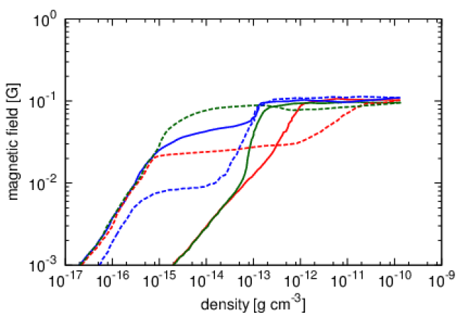
The ambipolar diffusion introduces an upper limit for the strength of magnetic field around the first core (Masson et al., 2016). To confirm this saturation also occurs in our simulations, we show the magnetic field strength along the - and -axes in Model0, Model90, and Model180, as a function of the density at each point in figure 15. We show that the profiles at the epochs at which central density is to allow the comparison with the results by Masson et al. (2016). The magnetic field is saturated at G and is in good agreement with the previous study (see figure 6 of Masson et al., 2016). Along the -axis of Model180, the saturation occurs at and magnetic field amplification by the central rotation is regulated even in region with such a low density. (see figure 2). This explains why the velocity of the outflow becomes small in the simulations, once the ambipolar diffusion is taken into account. The saturation at the center brakes once the thermal ionization has reached a certain degree, and the magnetic field and the gas couples again at K. We discuss why the magnetic-field saturation occurs at G in §5.4.
4.7 Relative importance of the magnetic diffusion
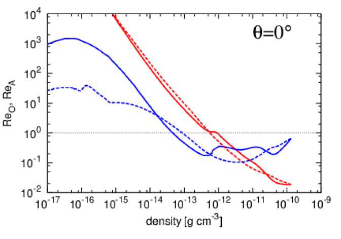
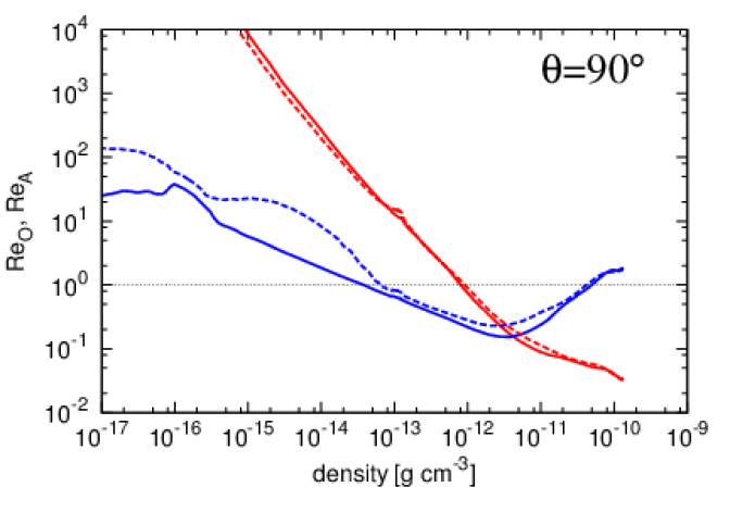
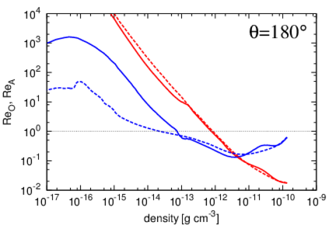
In this subsection, we investigate the relative importance of the magnetic diffusion. Figure 16 shows magnetic Reynolds numbers and along the - and -axes in Model0, Model90, and Model180. The magnetic Reynolds number is defined as
| (17) |
where and are a typical velocity and length-scale. Here, we assume and , where and are the scale-height of the self-gravitating sheet and free-fall time, respectively.
In all the simulations, holds for and the ambipolar diffusion extends the density range of the decoupled region (). The condition holds at , and the simulations show that decoupling occurs at one or two orders of magnitude smaller density by incorporating the ambipolar diffusion compared to the simulations only with Ohmic diffusion. On the other hand, the Ohmic diffusion surpasses the ambipolar diffusion in the central region of the first core . This suggests that simulations need to include the ambipolar diffusion to investigate precisely the phenomena, which occur at around the first core or new-born disks, including magnetic braking efficiency, magnetic flux evolution, and the outflow formation.
4.8 Does radial Hall drift play a role ?
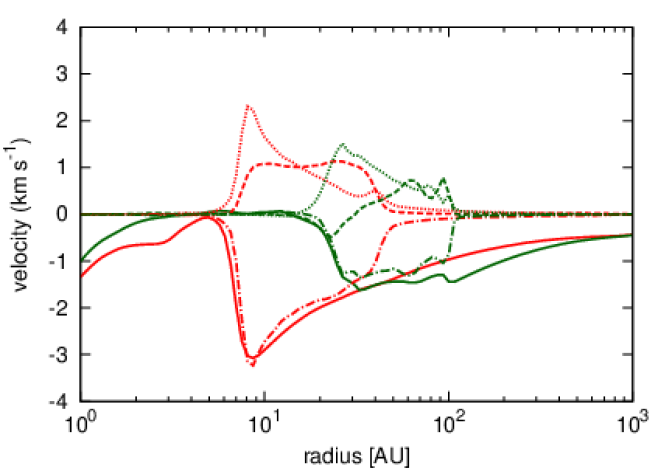
Bai & Stone (2017) show that the radial drift of the magnetic field induced by the Hall effect play an important role for the magnetic flux evolution in the circumstellar disk in the late evolutionary phase. Bai & Stone (2017) also suggested that the bimodal evolution of the disk size suggested in our previous paper (Tsukamoto et al., 2015a) is come from the difference of the direction of the Hall induced radial drift. Thus the influence of Hall effect on the magnetic flux evolution in the pseudo-disk is worth investigating. In this subsection, we examine the impact of the radial Hall drift.
Figure 17 shows the radial component of the gas velocity , the drift velocity induced by Hall effect , and that induced by ambipolar diffusion of Model0 and Model180 at the end of the simulations. In AU for Model0 and in AU for Model180, , and the inward magnetic field drift by the gas motion almost balances to the outward drift by the Hall effect and ambipolar diffusion.
In Model0 (red lines), the outward field drift induced by the ambipolar diffusion is stronger than that by the Hall effect at AU. On the other hand, the outward Hall drift velocity becomes larger in AU. Therefore, the Hall drift also contributes the outward field drift in Model0.
In Model180 (green lines), the outward drift is mainly caused by the ambipolar diffusion in AU and Hall drift has a minor role. The Hall drift changes its direction at AU and it is outward in AU and inward in AU. One may think that the outward Hall drift in Model180 is peculiar because drift direction should flip according to the global inversion of the magnetic field and should be inward in Model180. This behavior can be understood as follows. As shown in figure 9, the positive magnetic torque is exerted in AU on the midplane meaning that toroidal magnetic field is opposite to the gas rotation direction due to the strong azimuthal Hall drift. Because both the poloidal and toroidal field direction flip in AU in Model180 compared to Model0, the resultant Hall drift is outward in this region.
The situation is strikingly different from that of the (more evolved) circumstellar disks in which the fast gas rotation creates the strong toroidal field and azimuthal Hall drift is not significant. In such disks, the radial drift direction is solely determined by the direction of the poloidal field (inward for and outward for when is negative) and the sign of is crucial for the magnetic flux evolution.
On the other hand, our simulations show that the radial Hall drift is not a dominant process for the radial field drift and that the radial drift caused by the ambipolar diffusion primarily play a role. They also suggest that the radial Hall drift may not be a crucial for the bimodal disk evolution. Rather, the azimuthal Hall drift and resultant difference of the magnetic torque in the pseudo-disk is the crucial mechanism for the bimodal disk evolution.
5 Discussion
5.1 Bimodal evolution of disk size
The specific angular momenta of the acute-angle cores and obtuse-angle cores are considerably different (figure 6). This difference is caused by the global magnetic field configuration of whether the magnetic field and the initial angular momentum vector of the cloud core have an acute or obtuse relative angle. The global magnetic field configuration would not change significantly during the subsequent evolution of YSOs. Thus, the difference between acute-angle cores and obtuse-angle cores will be maintained or enhanced in the subsequent Class 0 phase although our simulations did not confirm it as we stop the calculation at the protostar formation epoch. Therefore, it is expected that the disks in acute-angle cores have relatively small radii, whereas those in obtuse-angle cores have relatively large radii, and that the bimodal evolution of disk size may occur in the Class 0 phase.
Recent observations of Class 0 YSOs have reported that some Class 0 YSOs possess the disks with radii of AU, such as VLA1623A, L1527IRS, and Lupus 3 MMS, (Tobin et al., 2012; Murillo et al., 2013; Ohashi et al., 2014; Yen et al., 2017, we hereafter refer to these objects as “large-disk population” of Class 0 YSOs), while there are Class 0 YSOs which do not have disks with radii of AU such as IRAS 15398-3559, IRAS 16253-2429, and B335 (Yen et al., 2015, 2017, hereafter, “small-disk population” of Class 0 YSOs). Yen et al. (2017) argued that one possible explanation why these two populations exist is the difference in the age. The estimated protostar mass of the small-disk population, is much smaller than those of large-disk population, (Yen et al., 2017), suggesting that the small-disk population is younger than the large-disk population. Hence, the difference of the disk size can be due to gradual growth of a disk as the protostar mass increases.
A potential problem of this interpretation which is also discussed in Yen et al. (2017) is that the protostar mass of small-disk population has been estimated on the assumption that the infalling velocity is equal to the free-fall velocity, and the estimated mass is usually a lower limit. Observations have shown that the infalling velocities in some Class 0/I YSOs are 30% to 50 % of their respective free-fall velocities (e.g., L1551 NE, TMC-1A, L1527 IRS; Takakuwa et al., 2013; Chou et al., 2014; Ohashi et al., 2014; Aso et al., 2015), and hence a priori assumption in the mass estimation actually breaks down in some cases. The inferred central star mass is proportional to the square of free-fall velocity as . Therefore an underestimation by 70% of the free-fall velocity, for example, leads to an order of magnitude underestimation of the protostar mass.
Another point is the discrepancy in the number of the detections of the two populations. If the mass, and hence the age of the small-disk populations, are typically 10 times smaller than those of the large disk population, the chance of detecting one in observations is 10 times smaller, and so is the detected number. However, in reality, the number of known small-disk population (three objects) is similar to that of the large-disk population (five objects) (Yen et al., 2017). This discrepancy also suggests that the protostar mass of the small-disk population is possibly underestimated.
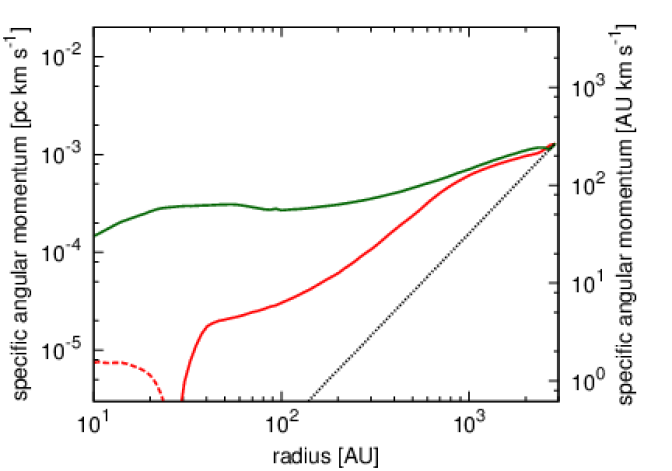
Alternatively, if the age of the small-disk population and that of the large-disk population are roughly equal, the difference in the disk size is possibly explained by the Hall effect. It is expected that the numbers of the acute- and obtuse-angle cloud cores are roughly equal to each other because the Hall effect may not play the role in the cloud core formation phase. Then, the Hall effect introduces a large difference of the angular momentum of the central region between acute-angle cores and obtuse-angle cores. This bimodal evolution of the disk size possibly explains the recent observational results. Furthermore, we conjecture that the observed specific angular momentum difference of the envelope of the large- and small- disk populations reported by Yen et al. (2017) can also be explained by the Hall effect. The Hall effect becomes efficient in the pseudo-disk and the considerable difference in the specific angular momentum is introduced in a relatively extended region (figure 2 and 6). In figure 18, we show the azimuthally averaged radial profile of the specific angular momentum of Model0 and Model180 on - plane. The specific angular momentum profile is found to have a large difference even at several AU. Both snapshots are taken at the epoch immediately after the protostar formation and the age of protostar is almost the same. Figure 18 can be compared with figure 9 of Yen et al. (2017). The observed specific angular momentum profiles of the large- and small- disk populations are similar to those in Model180 and Model0. Therefore, the difference in the specific angular momentum of the envelope between the large- and small-disk populations is also possibly explained by the Hall effect. Future statistical studies of the disk size with a larger sample of Class 0 YSOs may test our conjecture.
5.2 Direction of the central angular momentum
Unlike the magnitude of the angular momentum, the Hall-induced rotation affects the direction of the angular momentum at the central region (figure 13). This suggests that both the Hall-induced angular momentum and the inherent angular momentum contribute to the central angular momentum and the normal direction of the disks, in general, is parallel to neither the initial angular momentum of the cloud core nor to the initial magnetic field.
This implies that it is not straightforward to interpret the observations of the orientation of the magnetic field and the outflows of the YSOs. Hull et al. (2013, 2014) showed that the orientation of the global magnetic field is not correlated at a scale of AU with the outflow axis, which may trace the direction of the normal vector of the disk. In the standard practice in this field, one assumes that the angular momentum of the disk is parallel to that of the parent cloud cores, and interprets that the results by Hull et al. (2013, 2014) indicates that the direction of the magnetic field and the angular momentum of the parent cloud cores are randomly distributed. However, the angular momentum direction of the disk is not necessarily parallel to that of the initial cloud core. Therefore, we can not assert that the direction of the outflow follows that of the initial angular momentum of the core.
5.3 Counter rotation induced by the Hall effect
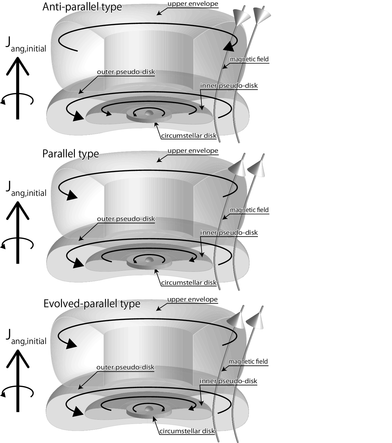
We found that two different types of counter-rotating structures are formed in acute- and obtuse- angle cloud cores (§4.3 and 4.4). The overall rotation structures are slightly complicated and it is worth showing their schematic diagrams.
In obtuse-angle cloud cores, counter-rotating envelopes form at the upper region of the pseudo-disk (panel (d) and (e) of figure 10). This type of counter-rotation is generated by the back-reaction of the Hall-induced forward-rotation at the midplane of the pseudo-disk. The overall rotation structure in obtuse-angle core is schematically shown in top diagram of figure 19 (we refer to this as “anti-parallel type” rotation structure). In the anti-parallel type, the gas rotation has the same direction on the midplane of the pseudo-disk. The overall rotation structure would not change in the subsequent mass accretion phase.
In acute-angle cloud cores, counter-rotation occurs at the inner region of the pseudo-disk (inner pseudo-disk). The counter-rotation is generated by the strong negative magnetic torque at the midplane due to the Hall effect. The overall rotation structure in acute-angle core is schematically shown in middle diagram of figure 19 (we refer to this as “parallel type” rotation structure). In parallel type, the gas rotation flips on the midplane of the pseudo-disk.
The parallel type rotating structure possibly evolves to the other type of rotation structure in the subsequent accretion phase. In the parallel type, the counter-rotating regions is connected to the circumstellar disk. When the total angular momentum flux onto the disk becomes negative, the disk rotation can flip during the accretion phase. If such a phenomenon happens, the disk rotation and the inner pseudo-disk rotation have the same direction which is opposite to that of the large-scale rotation as shown in bottom panel of figure 19 (we refer to this as “evolved-parallel type”). These three types of the counter-rotation possibly realize in Class 0/I phase when both the magnetic field and Hall effect play the role.
5.4 saturation of magnetic field introduced by the ambipolar diffusion
In §4.6, we confirm that the magnetic field saturates at G which is pointed out by Masson et al. (2016). Interestingly, the saturation occurs in broad density range of . This saturation is caused by ambipolar diffusion.
For the saturation, we argue that the deviation of from the simple analytic formula of (Shu, 1983)
| (18) |
is crucial although equation (18) is the basis of the analytic argument of Masson et al. (2016). Here, we adopt and . It have been pointed out that equation (18) is not good approximation for in because the collision between charged dust grains and neutrals dominates the momentum transfer by the ion-neutral interaction (Elmegreen, 1979; Nakano & Umebayashi, 1980; Shu, 1983) and recombination of ions on dust grains leads to the ion density (Umebayashi & Nakano, 1980).
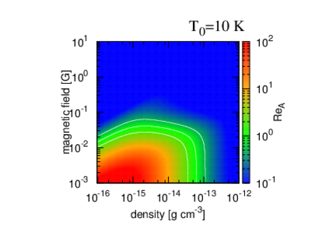
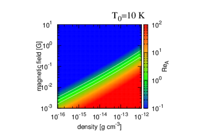
In figure 20, we show on - plane, where the temperature and sound speed are assumed to be and , respectively. We choose two values for as K and slightly higher value K. K is considered because the previous radiative magnetohydrodynamics simulations show that gas can be heated up in the relatively extended region by the radiation transfer at the protostar formation epoch (see, e.g., Tsukamoto et al., 2015b; Tomida et al., 2015).
The left panels show calculated from our resistivity table. They show that becomes at G and the boundary of is almost flat in . In G, the ambipolar diffusion efficiently dissipates the magnetic field. Thus once the magnetic field strength reaches G in , the ambipolar diffusion forbids further magnetic field amplification. As a result, the gas evolution tracks to horizontal direction on - plane. Note that, even when gas density increases to and becomes , the magnetic field does not necessarily decrease because of the magnetic flux conservation, although the increase of magnetic field is forbidden, and the evolution to a horizontal direction continues in . In this wise, the saturation of the magnetic field at G in is realized.
The right panels show calculated using equation (18). The boundary of is increasing function of the density as and the magnetic field can be amplified as the density increases without strong dissipation. In other words, the saturation value should depend on the density and G cannot be the characteristic value when we adopt equation (18). Therefore we argue that the deviation of from equation (18) in is crucial for the saturation of the magnetic field.
5.5 Does turbulent diffusion play the role in the newly born disk?
Magneto-rotational instability (MRI) (e.g., Balbus & Hawley, 1991; Sano et al., 2000; Wardle & Salmeron, 2012) may play a role in the subsequent disk evolutionary phase. In particular, the magnetic flux diffusion induced by the MRI driven turbulence (Guan & Gammie, 2009; Fromang & Stone, 2009) possibly affects the magnetic flux evolution in addition to that induced by the non-ideal MHD effect. Therefore it is important to estimate the impact of turbulent diffusion on the newborn disk.
The turbulent resistivity can be estimated as , where is the disk scale-height. is the magnetic Prandtl number and is the order of unity (e.g., Guan & Gammie, 2009). Thus we assume . is the parameter (Shakura & Sunyaev, 1973) induced by MRI. By assuming the disk radius, temperature, and aspect ratio are AU and K, and which is expected from our previous studies (for example, the size of rotationally supported disk in Model180 is AU Tsukamoto et al., 2015a), can be estimated as . This value is typically times smaller than the resistivities shown in figure 8 and turbulent diffusion may not play a significant role in the early disk evolution.
5.6 Unsolved issues and future prospect
Our simulations incorporate several key physics, most notably all the non-ideal MHD effects and radiation transfer, and are one of the most realistic calculations ever conducted on this subject. Nonetheless, there are still some unresolved issues, as discussed in this subsection, which should be addressed in future studies.
Our simulations use a resistivity model based on the calculations by Nakano et al. (2002) and Okuzumi (2009). However, magnetic resistivity models are known to have a large uncertainty and they vary significantly from model to model, depending on the dust property, the chemical network, and the cosmic ray ionization rate (Nishi et al., 1991; Dapp et al., 2012; Susa et al., 2015; Dzyurkevich et al., 2017). In particular, the dust can grow in relatively short timescale and its size distribution and abundance possibly change even in very early phase of disk evolution (e.g., Birnstiel et al., 2010; Tsukamoto et al., 2017). Dzyurkevich et al. (2017) recently pointed out that the degree of impact by the ambipolar diffusion and Hall effect may depend on the dust property of the star forming region, which may introduce the variety in the disk formation and evolution processes. Hence, simulations with different resistivity models would be a desirable next step.
Another issue is how the Hall effect affects the protostar and disk evolution in the subsequent mass-accretion phase. Our simulations are terminated at the epoch immediately after the protostar formation and the impact of the hall effect in the mass-accretion phase is unclear. The typical age of protostar of the observed Class 0 YSOs is yr and the epochs between the simulations and the observations are different. The age difference makes the quantitative comparison between the simulations and observations difficult. The simulations covering a more extended period with appropriate inner boundary conditions, such as Machida et al. (2010, 2011a) and Tomida et al. (2017) would allow us to make the direct quantitative comparison between observations and theoretical studies.
5.7 Summary
In this paper, we investigated the impact of the non-ideal MHD effects in molecular cloud cores in which the magnetic field and angular momentum are mutually misaligned. In particular, we have focused on the role of the Hall effect in the cores of that kind. Our findings are summarized as follows.
-
1.
The mean specific angular momentum of the central dense region with the density weakly depends on the mutual angle in and . The central angular momentum of acute-angle cores and that of obtuse-angle cores are notably different. The Hall-induced bimodal evolution of disk size, which was suggested in our previous paper in the cases where the magnetic field and the angular momentum of cloud cores are aligned (Tsukamoto et al., 2015a), is expected even when they are not aligned (see section 4.2 and 5.1 for details).
-
2.
Counter-rotating envelopes form at the upper region of the pseudo-disk in obtuse-angle cloud cores. The counter-rotation is generated by the back-reaction of the Hall-induced forward-rotation at the midplane of the pseudo-disk. The counter-rotating envelopes have the size of several 100 AU and the velocity of , and have the right-handed screw direction of the poloidal magnetic field of the pseudo-disk. Given that the Hall effect enhances the central rotation in obtuse-angle cloud cores, this kind of counter-rotation may be associated with the YSOs with large disk radii (see section 4.3 and 5.3 for details).
-
3.
We have found another kind of counter rotation occurred in acute-angle cloud cores. In such cores, counter-rotation appears at the midplane of the pseudo-disk. The size and rotation velocity of the region are AU and , respectively. The counter-rotation is generated by the strong negative magnetic torque at the midplane, which is generated by the Hall effect. We expect that this kind of counter-rotation may be associated with the YSOs with small disk radii (see section 4.4 and 5.3 for details).
-
4.
The Hall effect affects the direction of the angular momentum at the central region so that it becomes not parallel to the initial magnetic field or initial angular momentum of the core. This suggests that the normal direction of the disk is parallel to neither the initial angular momentum nor the initial magnetic field of the cloud cores, when both the Hall-induced rotation and the inherent rotation of the core contribute to the central angular momentum (see section 4.5 and 5.2 for details).
Acknowledgments
We thank K. Tomida and Y. Hori for providing us with their EOS table, which was used in Tomida et al. (2013). We also thank T. Matsumoto for his advice on how to make the schematic figure. We also thank anonymous referee for insightful comments. The computations were performed on a parallel computer, XC40 system at CfCA of NAOJ.
References
- Alexiades et al. (1996) Alexiades, V., Amiez, G., & Gremaud, P.-A. 1996, Com. Num. Meth. Eng, 12, 12
- Allen et al. (2003) Allen, A., Li, Z.-Y., & Shu, F. H. 2003, ApJ, 599, 363
- Aso et al. (2015) Aso, Y., Ohashi, N., Saigo, K., Koyamatsu, S., Aikawa, Y., Hayashi, M., Machida, M. N., Saito, M., Takakuwa, S., Tomida, K., Tomisaka, K., & Yen, H.-W. 2015, ApJ, 812, 27
- Bai & Stone (2017) Bai, X.-N. & Stone, J. M. 2017, ApJ, 836, 46
- Balbus & Hawley (1991) Balbus, S. A. & Hawley, J. F. 1991, ApJ, 376, 214
- Barnes & Hut (1986) Barnes, J. & Hut, P. 1986, Nature, 324, 446
- Birnstiel et al. (2010) Birnstiel, T., Dullemond, C. P., & Brauer, F. 2010, A&A, 513, A79
- Braiding & Wardle (2012a) Braiding, C. R. & Wardle, M. 2012a, MNRAS, 427, 3188
- Braiding & Wardle (2012b) —. 2012b, MNRAS, 422, 261
- Chou et al. (2014) Chou, T.-L., Takakuwa, S., Yen, H.-W., Ohashi, N., & Ho, P. T. P. 2014, ApJ, 796, 70
- Commerçon et al. (2010) Commerçon, B., Hennebelle, P., Audit, E., Chabrier, G., & Teyssier, R. 2010, A&A, 510, L3
- Dapp et al. (2012) Dapp, W. B., Basu, S., & Kunz, M. W. 2012, A&A, 541, A35
- Dzyurkevich et al. (2017) Dzyurkevich, N., Commercon, B., Lesaffre, P., & Semenov, D. 2017, ArXiv e-prints
- Elmegreen (1979) Elmegreen, B. G. 1979, ApJ, 232, 729
- Ferguson et al. (2005) Ferguson, J. W., Alexander, D. R., Allard, F., Barman, T., Bodnarik, J. G., Hauschildt, P. H., Heffner-Wong, A., & Tamanai, A. 2005, ApJ, 623, 585
- Fromang & Stone (2009) Fromang, S. & Stone, J. M. 2009, A&A, 507, 19
- Galli & Shu (1993) Galli, D. & Shu, F. H. 1993, ApJ, 417, 220
- Gillis et al. (1974) Gillis, J., Mestel, L., & Paris, R. B. 1974, Ap&SS, 27, 167
- Guan & Gammie (2009) Guan, X. & Gammie, C. F. 2009, ApJ, 697, 1901
- Hennebelle & Ciardi (2009) Hennebelle, P. & Ciardi, A. 2009, A&A, 506, L29
- Hennebelle & Fromang (2008) Hennebelle, P. & Fromang, S. 2008, A&A, 477, 9
- Hull et al. (2013) Hull, C. L. H., Plambeck, R. L., Bolatto, A. D., Bower, G. C., Carpenter, J. M., Crutcher, R. M., Fiege, J. D., Franzmann, E., Hakobian, N. S., Heiles, C., Houde, M., Hughes, A. M., Jameson, K., Kwon, W., Lamb, J. W., Looney, L. W., Matthews, B. C., Mundy, L., Pillai, T., Pound, M. W., Stephens, I. W., Tobin, J. J., Vaillancourt, J. E., Volgenau, N. H., & Wright, M. C. H. 2013, ApJ, 768, 159
- Hull et al. (2014) Hull, C. L. H., Plambeck, R. L., Kwon, W., Bower, G. C., Carpenter, J. M., Crutcher, R. M., Fiege, J. D., Franzmann, E., Hakobian, N. S., Heiles, C., Houde, M., Hughes, A. M., Lamb, J. W., Looney, L. W., Marrone, D. P., Matthews, B. C., Pillai, T., Pound, M. W., Rahman, N., Sandell, G., Stephens, I. W., Tobin, J. J., Vaillancourt, J. E., Volgenau, N. H., & Wright, M. C. H. 2014, ApJS, 213, 13
- Inutsuka (2012) Inutsuka, S. 2012, Prog. Theor. Exp. Phys., 2012, 307
- Inutsuka et al. (2010) Inutsuka, S., Machida, M. N., & Matsumoto, T. 2010, ApJ, 718, L58
- Iwasaki & Inutsuka (2011) Iwasaki, K. & Inutsuka, S. 2011, MNRAS, 418, 1668
- Iwasaki & Inutsuka (2013) Iwasaki, K. & Inutsuka, S. 2013, in Astronomical Society of the Pacific Conference Series, Vol. 474, Numerical Modeling of Space Plasma Flows (ASTRONUM2012), ed. N. V. Pogorelov, E. Audit, & G. P. Zank, 239
- Joos et al. (2012) Joos, M., Hennebelle, P., & Ciardi, A. 2012, A&A, 543, A128
- Krasnopolsky et al. (2011) Krasnopolsky, R., Li, Z.-Y., & Shang, H. 2011, ApJ, 733, 54
- Larson (1969) Larson, R. B. 1969, MNRAS, 145, 271
- Lewis & Bate (2017) Lewis, B. T. & Bate, M. R. 2017, MNRAS, 467, 3324
- Li et al. (2011) Li, Z.-Y., Krasnopolsky, R., & Shang, H. 2011, ApJ, 738, 180
- Li et al. (2013) —. 2013, ApJ, 774, 82
- Machida et al. (2007) Machida, M. N., Inutsuka, S., & Matsumoto, T. 2007, ApJ, 670, 1198
- Machida et al. (2010) —. 2010, ApJ, 724, 1006
- Machida et al. (2011a) —. 2011a, PASJ, 63, 555
- Machida et al. (2011b) —. 2011b, ApJ, 729, 42
- Machida et al. (2014) —. 2014, MNRAS, 438, 2278
- Machida & Matsumoto (2011) Machida, M. N. & Matsumoto, T. 2011, MNRAS, 413, 2767
- Machida et al. (2016) Machida, M. N., Matsumoto, T., & Inutsuka, S. 2016, MNRAS, 463, 4246
- Machida et al. (2004) Machida, M. N., Tomisaka, K., & Matsumoto, T. 2004, MNRAS, 348, L1
- Marchand et al. (2016) Marchand, P., Masson, J., Chabrier, G., Hennebelle, P., Commerçon, B., & Vaytet, N. 2016, A&A, 592, A18
- Masson et al. (2016) Masson, J., Chabrier, G., Hennebelle, P., Vaytet, N., & Commerçon, B. 2016, A&A, 587, A32
- Masunaga & Inutsuka (1999) Masunaga, H. & Inutsuka, S. 1999, ApJ, 510, 822
- Masunaga et al. (1998) Masunaga, H., Miyama, S. M., & Inutsuka, S. 1998, ApJ, 495, 346
- Matsumoto & Tomisaka (2004) Matsumoto, T. & Tomisaka, K. 2004, ApJ, 616, 266
- Mellon & Li (2008) Mellon, R. R. & Li, Z.-Y. 2008, ApJ, 681, 1356
- Monaghan (1992) Monaghan, J. J. 1992, ARA&A, 30, 543
- Monaghan & Lattanzio (1985) Monaghan, J. J. & Lattanzio, J. C. 1985, A&A, 149, 135
- Mouschovias (1985) Mouschovias, T. C. 1985, A&A, 142, 41
- Mouschovias & Spitzer (1976) Mouschovias, T. C. & Spitzer, Jr., L. 1976, ApJ, 210, 326
- Murillo et al. (2013) Murillo, N. M., Lai, S.-P., Bruderer, S., Harsono, D., & van Dishoeck, E. F. 2013, A&A, 560, A103
- Nakano et al. (2002) Nakano, T., Nishi, R., & Umebayashi, T. 2002, ApJ, 573, 199
- Nakano & Umebayashi (1980) Nakano, T. & Umebayashi, T. 1980, PASJ, 32, 613
- Nishi et al. (1991) Nishi, R., Nakano, T., & Umebayashi, T. 1991, ApJ, 368, 181
- Ohashi et al. (2014) Ohashi, N., Saigo, K., Aso, Y., Aikawa, Y., Koyamatsu, S., Machida, M. N., Saito, M., Takahashi, S. Z., Takakuwa, S., Tomida, K., Tomisaka, K., & Yen, H.-W. 2014, ApJ, 796, 131
- Okuzumi (2009) Okuzumi, S. 2009, ApJ, 698, 1122
- Price & Bate (2007a) Price, D. J. & Bate, M. R. 2007a, Ap&SS, 311, 75
- Price & Bate (2007b) —. 2007b, MNRAS, 377, 77
- Saigo & Tomisaka (2006) Saigo, K. & Tomisaka, K. 2006, ApJ, 645, 381
- Sano et al. (2000) Sano, T., Miyama, S. M., Umebayashi, T., & Nakano, T. 2000, ApJ, 543, 486
- Semenov et al. (2003) Semenov, D., Henning, T., Helling, C., Ilgner, M., & Sedlmayr, E. 2003, A&A, 410, 611
- Shakura & Sunyaev (1973) Shakura, N. I. & Sunyaev, R. A. 1973, A&A, 24, 337
- Shu (1983) Shu, F. H. 1983, ApJ, 273, 202
- Susa et al. (2015) Susa, H., Doi, K., & Omukai, K. 2015, ApJ, 801, 13
- Takakuwa et al. (2013) Takakuwa, S., Saito, M., Lim, J., & Saigo, K. 2013, ApJ, 776, 51
- Tobin et al. (2012) Tobin, J. J., Hartmann, L., Chiang, H.-F., Wilner, D. J., Looney, L. W., Loinard, L., Calvet, N., & D’Alessio, P. 2012, Nature, 492, 83
- Tomida et al. (2017) Tomida, K., Machida, M. N., Hosokawa, T., Sakurai, Y., & Lin, C. H. 2017, ApJ, 835, L11
- Tomida et al. (2015) Tomida, K., Okuzumi, S., & Machida, M. N. 2015, ApJ, 801, 117
- Tomida et al. (2013) Tomida, K., Tomisaka, K., Matsumoto, T., Hori, Y., Okuzumi, S., Machida, M. N., & Saigo, K. 2013, ApJ, 763, 6
- Tomisaka (2002) Tomisaka, K. 2002, ApJ, 575, 306
- Tsukamoto (2016) Tsukamoto, Y. 2016, PASA, 33, e010
- Tsukamoto et al. (2013a) Tsukamoto, Y., Iwasaki, K., & Inutsuka, S. 2013a, MNRAS, 434, 2593
- Tsukamoto et al. (2015a) Tsukamoto, Y., Iwasaki, K., Okuzumi, S., Machida, M. N., & Inutsuka, S. 2015a, ApJ, 810, L26
- Tsukamoto et al. (2015b) —. 2015b, MNRAS, 452, 278
- Tsukamoto & Machida (2011) Tsukamoto, Y. & Machida, M. N. 2011, MNRAS, 416, 591
- Tsukamoto & Machida (2013) —. 2013, MNRAS, 428, 1321
- Tsukamoto et al. (2013b) Tsukamoto, Y., Machida, M. N., & Inutsuka, S. 2013b, MNRAS, 436, 1667
- Tsukamoto et al. (2017) Tsukamoto, Y., Okuzumi, S., & Kataoka, A. 2017, ApJ, 838, 151
- Tsukamoto et al. (2015c) Tsukamoto, Y., Takahashi, S. Z., Machida, M. N., & Inutsuka, S. 2015c, MNRAS, 446, 1175
- Umebayashi & Nakano (1980) Umebayashi, T. & Nakano, T. 1980, PASJ, 32, 405
- Umebayashi & Nakano (1990) —. 1990, MNRAS, 243, 103
- Vaytet et al. (2012) Vaytet, N., Audit, E., Chabrier, G., Commerçon, B., & Masson, J. 2012, A&A, 543, A60
- Vaytet & Haugbølle (2017) Vaytet, N. & Haugbølle, T. 2017, A&A, 598, A116
- Vorobyov et al. (2015) Vorobyov, E. I., Lin, D. N. C., & Guedel, M. 2015, A&A, 573, A5
- Vorobyov et al. (2016) Vorobyov, E. I., Regaly, Z., Guedel, M., & Lin, D. N. C. 2016, A&A, 587, A146
- Wardle (2004) Wardle, M. 2004, Ap&SS, 292, 317
- Wardle & Ng (1999) Wardle, M. & Ng, C. 1999, MNRAS, 303, 239
- Wardle & Salmeron (2012) Wardle, M. & Salmeron, R. 2012, MNRAS, 422, 2737
- Whitehouse & Bate (2004) Whitehouse, S. C. & Bate, M. R. 2004, MNRAS, 353, 1078
- Whitehouse et al. (2005) Whitehouse, S. C., Bate, M. R., & Monaghan, J. J. 2005, MNRAS, 364, 1367
- Wurster (2016) Wurster, J. 2016, PASA, 33, e041
- Wurster et al. (2014) Wurster, J., Price, D., & Ayliffe, B. 2014, MNRAS, 444, 1104
- Wurster et al. (2016) Wurster, J., Price, D. J., & Bate, M. R. 2016, MNRAS, 457, 1037
- Yen et al. (2017) Yen, H.-W., Koch, P. M., Takakuwa, S., Krasnopolsky, R., Ohashi, N., & Aso, Y. 2017, ApJ, 834, 178
- Yen et al. (2015) Yen, H.-W., Takakuwa, S., Koch, P. M., Aso, Y., Koyamatsu, S., Krasnopolsky, R., & Ohashi, N. 2015, ApJ, 812, 129