CoMaL Tracking: Tracking Points at the Object Boundaries
Abstract
Traditional point tracking algorithms such as the KLT use local 2D information aggregation for feature detection and tracking, due to which their performance degrades at the object boundaries that separate multiple objects. Recently, CoMaL Features have been proposed that handle such a case. However, they proposed a simple tracking framework where the points are re-detected in each frame and matched. This is inefficient and may also lose many points that are not re-detected in the next frame. We propose a novel tracking algorithm to accurately and efficiently track CoMaL points. For this, the level line segment associated with the CoMaL points is matched to MSER segments in the next frame using shape-based matching and the matches are further filtered using texture-based matching. Experiments show improvements over a simple re-detect-and-match framework as well as KLT in terms of speed/accuracy on different real-world applications, especially at the object boundaries.
1 Introduction
Feature Point Detection, Matching and Tracking is an important problem that has been studied extensively in the Computer Vision literature and has numerous applications such as Mosaicing, Object Tracking [33, 35, 8], Action Recognition [37, 17, 18, 38] and Structure-from-Motion [1, 5, 25] among others. The Kanade-Lukas-Tomasi (KLT) [15, 36, 30] tracker is still the most widely used tracker in the literature even after 30 years due to its robustness and speed. In KLT, Harris corners [13] are detected in the first frame and are subsequently tracked using iterative search of the matching image patch around the detected point using a gradient descent approach. Several extensions to the original KLT have been proposed. For instance, [3] proposes several variations of the original KLT algorithm, while [4] improves its efficiency. GPU-based extensions [31, 39] of KLT have also been proposed to obtain significant speed-ups over the traditional implementations.
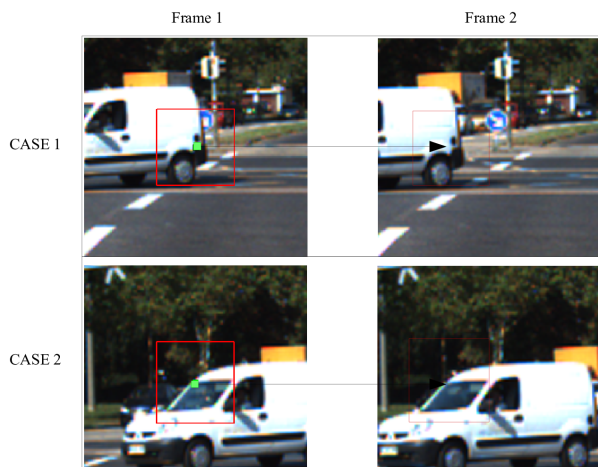
While KLT has been the state-of-the art for feature point tracking, other methods have also been proposed [6, 11] and can be used for Feature Point Detection and Tracking. However, almost all these methods including the KLT work well only in the interior of objects and do not perform very well at the object boundaries. This is due to the consideration of a full 2D support region around a point for matching which can be problematic at the object boundaries where the background portion of the support region can change. This is illustrated in Figure 1.
There have been other algorithms to address the issue of varying backgrounds in the boundary regions of objects. Mikolajczyk et al. [22] use edge-based features and identify the dominant edge to separate the two regions at the object boundary for the problem of Object Recognition. For the task of Object Tracking, SegTrack [2], Chen et al. [9] and Oron et al. [24] iteratively build foreground and background appearance models for robust object tracking. However, these methods degrade in performance when the object boundaries dominate the object appearance (as in the case of thin objects) and require a good initilization to iteratively segment the foreground and the background.
The CoMaL Point Detector [26] has been proposed recently, which addresses many of such issues at the Object oundaries without the need for a good initialization and an iterative approach. It is based on the idea of level lines that often separate the foreground from the background and are fairly robust to illumination changes happening on one side of the divide. Furthermore, CoMaL Point Matching allows for matching only one of the two sides of the level line, thus making it invariant to a change on one side due to a background change. It has also been observed in the literature that Maximally Stable Extremal Regions (MSERs) [16], the seminal work that originally used such level lines for Point Detection, are quite robust compared to other corner points since they are invariant to an affine transformation of image intensities [16, 21], and were also found to be extremely stable [16] and highly repeatable in many comparative studies [19, 21].
Although the CoMaL features are very good for the case of stable Feature Point Detection and Re-detection/Matching at the Object boundaries, the problem of tracking in continuous videos remained unaddressed, although this can be done naively by re-detecting all points in the next frame and matching. However, such an approach will fail if the corresponding feature point does not get detected in the next frame. Furthermore, feature point detection for each frame is an expensive step and reduces the efficiency of tracking. We propose an alternate algorithm for tracking CoMaL points with several contributions. First, instead of re-detecting the points again for each frame which is an expensive step, we search for the corners present in the previous frame in some given neighborhood. This makes it not only efficient but also alleviates the problem of missed corner point detections. Second, in order to do such a search, we first do a shape-based matching of the level line segment associated with a given corner point in the neighborhood. Such a matching is done on the MSER boundaries found in the next image and not on the edge map, which makes the method quite robust. Third, as in the original CoMaL work [26], we further filter such matches by doing an SSD matching on one side of the CoMaL level line. All these steps are robust to changes on one side of the level line and yield a method for tracking CoMaL points that works reliably and efficiently at object boundaries.
We first give a review of the CoMaL Point Detector [26], which are used as a base for our tracker.
2 The CoMaL Corners
The CoMaL Feature Point Detector [26] identifies corners on iso-intensity curves or level lines. Such level lines have been found to be fairly stable under many image transformations and have been used as a base for several Feature Point detectors such as MSER [16] and CoMaL. They can also be reliably detected at the object boundaries, which they often trace. The CoMaL Corners are identified as the points of high curvature on stable portions of long level lines, i.e., a corner point must satisfy two conditions: (a) It must lie on a stable level line segment and (b) have a high “cornerness” value at a given scale. The stability of a level line segment is inversely proportional to the area between it’s two neighbouring level line segments and signifies the motion of the level line upon a certain change in the intensity. The cornerness measure is defined based on the eigen values of the point distribution centered around the corner at a particular scale on the level line and large eigen values in both directions signify a “turn” of the level line at that point and hence a corner point.
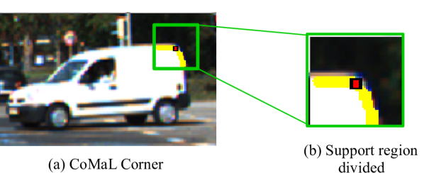
CoMaL points were shown to be more reliable and stable on the object boundaries compared to other feature point detectors such as FAST [27], Harris [13], Hessian [20] and MSER [16], and comparable to them in the interior of objects in the original CoMaL paper [26]. Also, the paper developed a reliable approach for matching corners at object boundaries by dividing the support region of the corner by the CoMaL level line into two regions, as shown in Figure 2. By independently matching the two regions, it allows us to compute a part SSD score by matching only one part of the support regions of the two corner points. Thus, if there is a change due to a background change in one of the parts, it can be neglected. As a result, it allows robust matching of feature points across images even where the background may not be fixed. Due to these characteristics of the CoMaL Feature Point Detector, such points are quite suitable for being tracked reliably at the object boundaries. How we do so is described in the next section.
3 The Tracking Algorithm
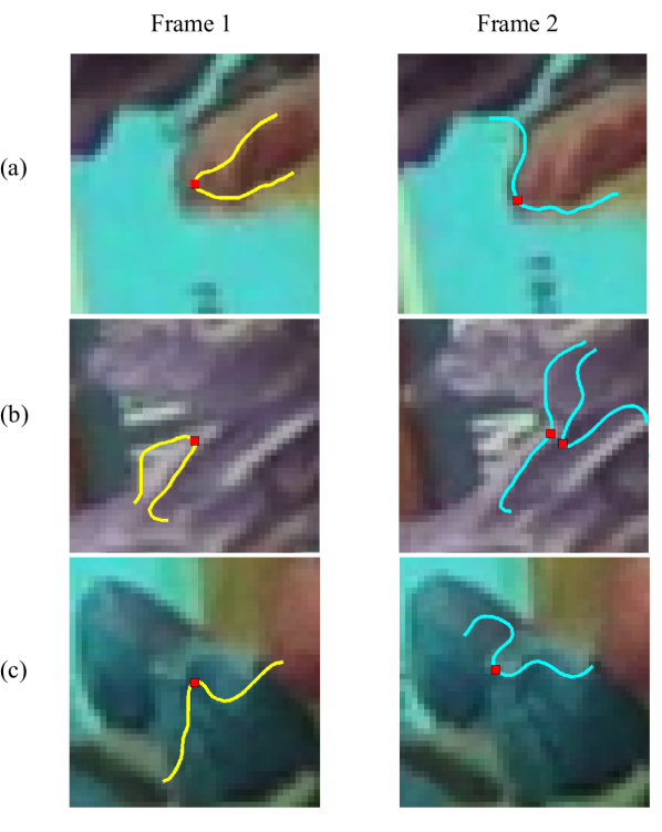
The original CoMaL Point Detector paper [26] presents a method for matching points across frames. This method can be used for tracking as well by simply re-detecting points in the next frame and matching to the points in the previous frame. However, apart from being slow, the re-detect-and-match method can fail if the corner in the next frame is not detected at the same position. This can happen if the corresponding point in the next frame falls below the cornerness threshold due to minor object deformations, illumination changes or if the corresponding level line segment was not stable in the next frame. Examples are shown in Figure 3. As we can see, the CoMaL Detector does not detect the corresponding corner in the second frame in the three cases shown. If we look at the cases more closely, corner detection could have failed if the corresponding level line segment was not maximally stable or if the corresponding point was not identified as a corner on the stable level line segment. Due to such missed points, the given point will not be tracked correctly in the next frame. Furthermore, this method is slow due to the high computational cost of point re-detection. In this section, we describe a more efficient algorithm for tracking points across frames.
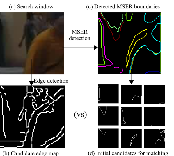
We first try to track the level lines associated with the CoMaL corners. The full corner patch cannot be tracked as a portion of the patch may have changed due to a background change. Contour matching techniques can be used to track the level lines segments by matching them with edges in the search region. However, the problem with this approach is that they can be over-segmented and broken due to loss of gradients along some portion of the level line as shown in Figure 5. Furthermore, the level line segment can match to edges belonging to multiple level lines in the current image, which can lead to an erroneous match. To address this issue, we only match the given level line segment with the individual stable level lines in the current frame, which can be obtained easily using MSER boundary segments (Figure 5). Since we know that CoMaL corners lie on stable level lines, matching the corner’s level line segment with locally stable level line segments in the next frame is a more compatible way to match than matching them with edges in the next frame since we would be searching for only stable level lines in the current frame that are similar in shape to the CoMaL level line. In order to account for possible loss of strength of the level line stability, the stable level lines are extracted with a lower threshold than is done in the CoMaL point detector (The detector needs to have a higher threshold so as to not detect weak corners, but we can afford it since we are only searching for the corner that was already detected in a previous frame.).
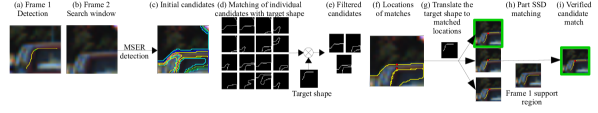
Once the matching stable level lines are shortlisted by shape matching, the matching points are further verified by part SSD patch matching (matching only one side of the level line) as in the CoMaL matcher to screen out any false matches in the first stage. Our tracking algorithm can thus be divided into two phases (Figure 4):
-
1.
Shortlisting candidate matches using shape-based matching of stable level-line matches
-
2.
Verification of filtered candidates using part SSD Matching
3.1 Shortlisting Candidates using Shape Matching
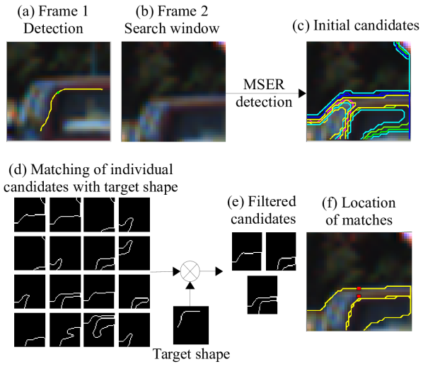
In order to shortlist candidate matches in the search region, we first perform an MSER [16] detection in a local image patch and find stable local level line segments. These, individually, form an initial set of target matching contour segments for the given CoMaL level line. MSERs are detected in the search window and their boundary segments are obtained (Figure 6 (c)). (In practice, this step is speeded up by pre-computing MSERs in local image windows. Then, for each point, we simply select the window closest to the search window and truncate it to the size needed.). As explained before, selecting MSER boundary segments as candidates for tracking is more compatible with the CoMaL corner detector compared to directly using edges because the CoMaL corners lie on level line segments. Next, we filter out the poorly matching candidates by computing a shape-based matching score between the level line segment of the corner and each candidate, and reject the candidates which have low matching scores. Note that this is done individually for each MSER segment separately. Note also that the shape of the level line does not typically change even in the presence of a background change on one side of the level line, even as the level line might stride the object boundary. Thus, this step can be done accurately even when the CoMaL point is at an object boundary.
We perform shape-based matching as shown in Figure 6 (d). We have used Hierarchical Chamfer matching(HCMA) [7] to obtain a matching score between the candidates and the level line segment of the corner. Other matching methods could be potentially used in place of HCMA, depending on the requirements of the tracker, however, we use HCMA in our implementation because it is extremely fast and sufficient to obtain reliable matches across adjacent frames. In HCMA, matching begins at a low resolution and only the regions which were not rejected at lower resolutions are explored at higher resolutions. The matching score is computed at the highest resolution using a Chamfer Matching criteria (average distance to the nearest edge point in the target image).
Most of the incorrect matches are filtered in this step, but a few matches are often left as shape is not fully discriminative. Also, taking the best match by using only the shape criteria is sometimes not correct as the shape of the level line changes sometimes. In order to select the best match, we next perform a texture-based verification step, the score of which is taken as the final score for selecting the best match.
3.2 Match Verification using Part SSD Matching
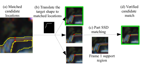
Given the restricted set of candidates in the search window, we want to find the candidate that best matches with the CoMaL corner in the current frame. We perform texture-based verification to select the best matching candidate among the filtered candidates. In our algorithm, we use part SSD matching [26] to obtain the matching scores between the candidate MSER boundary segments and the level line segment of the original CoMaL corner. Part SSD matching independently matches the two parts of the support region divided by the level line, leading to four possible matching combinations for a given pair of candidate and corner level line segment. The best matching combination is selected and the corresponding score is reported as the matching score between the pair. This is vital for tracking points on the object boundaries because the background keeps changing, so only the object portion of the support region can be reliably matched. As a result, this technique is better than a straight-forward full patch based SSD at the object boundaries. Other sophisticated techniques such as HOG [10], normalized cross-correlation, SIFT [20], etc. could potentially be used for more generalized matching scenarios, although they would have to be modified for part matching, which may not be easy. Also, gradient-based matching may not be suitable for partial patch matching as only one side of the level line is used which may be homogenous. Furthermore, these methods introduce invariances to certain transformations which may not be present in tracking applications, where there is limited variation across nearby frames. This can unnecessarily introduce some false matches. Thus, exact patch matching using SSD performs better in this scenario and is the basis for the KLT tracker as well. The score obtained from such part SSD matching is used to select the best match as shown in Figure 7. This two-stage selection process enables us to use both the shape and the texture information of the corner and its support region for matching and is thus fairly robust.
Our tracking algorithm is also more efficient than the re-detect-and-match framework. This is because we do not perform the expensive step of corner detection in every frame. Also, the part SSD matching algorithm used is more expensive because 4 independent matches have to be computed for each pair of corners as opposed to only one match for us (since the side that matches can be kept track of). Also, we do not do an iterative optimization step for corner point optimization as in CoMaL point detection (this is not required as we are only tracking and not finding the corner afresh), and only do MSER detection once in local image overlapping patch segments. All this is far less expensive than full-blown CoMaL corner detection.
4 Experimental setup and Results
4.1 Baselines
We consider two baseline algorithms for comparisons.
4.1.1 The KLT Tracker
The first baseline we use is the KLT tracker [15], which has been consistently used in applications such as Action Recognition [37, 17, 18, 38], Vehicle Tracking [33, 35, 8], 3D Reconstruction [1, 5, 25] in recent literature and is still the state-of-the-art even though it was proposed in 1981, suggesting it’s effectiveness on a variety of applications. As explained in Section 1, KLT may fail to track points on the object boundaries effectively as it uses the whole patch, which may not remain stable at the object boundaries. We used the inverse compositional algorithm implementation of KLT in our experiments as this was shown to give the best results in the literature [4].
4.1.2 CoMaL Point Re-detect-and-Match Approach
The second baseline we use is the original CoMaL paper’s re-detect-and-match approach [26], which was shown to perform better than other combinations of detectors and descriptors for detection and matching of feature points at the object boundaries. While such re-detection and matching of features is essential after every frames due to lost points and will be essential in a complete system along with the tracking approach presented in this paper, this comparison serves to demonstrate the advantage of our algorithm over this simple re-detect-and-match strategy using the same detector and matcher. We do not compare our results with other combinations of feature point detectors and descriptors since the CoMaL points were already shown to be much superior to the others for this task. Also, such an approach does not do as well in general as a tracking approach used by trackers such as the KLT, which do not rely on a re-detection step which can miss some points, leading to a higher error while tracking. Hence, comparisons with these other re-detect-and-match feature detectors and descriptors is not provided in this paper and the reader is referred to the original CoMaL paper [26] for such comparisons.
4.2 The Evaluation Framework
Since our datasets contain only object bounding box information and not exact point matching data, we generate the ground truth for point matching similar to [26]. We assume that the relative location of a point w.r.t. the annotated bounding box remains the same across frames. In order to account for non-rigidity of the objects and errors in the bounding box annotations, we allow small amounts of error between the ground truth location and the predicted match. The allowance given was 15 pixels in all the datasets. A common scale value of was selected for both the Harris and CoMaL detectors to allow for a fair comparison. A support region of dimensions is used. Since the precision-recall depends on the number of points generated by a detector using a threshold, we equalize the number of points generated by the point detectors on the different datasets. The corner function from MATLAB was used to obtain the Harris corner points and the quality and sensitivity parameters were varied in order to obtain a varying number of Harris corner points. Similarly, cornerness and stability threshold were varied for the CoMaL points as in the original paper.
Following the evaluation protocol of [26], the matching accuracy or precision is defined as the ratio of the number of correct matches to the total number of obtained matches. Since the number of correct matches varies with the precision, as in [26], we report the number of correct matches obtained at a given precision, averaged over all the frames, to compare our algorithm with the baselines. Our scores are reported as and a higher number of matches that are successfully tracked at the same precision indicate a better tracker. If the total number of original points detected by the different detectors is the same (which is not always possible to achieve in practice), this also indicates a higher recall at the same precision. We have chosen a typical operating precision value of around 0.8 for comparisons, although we had to decrease or increase this a bit to 0.7 or 0.9 for some sequences if the number of points was too little or too many at 0.8 precision.
4.3 Results
In our experiments, we show results on three different domains. In the first domain, we test our algorithm on a dataset for Object Tracking in a controlled setting that allows us to evaluate in detail the tracking performance on boundary non-boundary regions for the different approaches. Next, we present results on Vehicle Tracking, which is a more realistic and critical application, but does not have much object rotation as in the first dataset. We compare our results with KLT and CoMaL re-detect-and-match, and show superior performance on the boundaries of objects when compared to KLT and an overall improvement when compared with CoMaL re-detect-and-match in almost all cases. This can potentially improve the performance of existing vehicle tracking systems which use KLT [33, 35, 32]. Finally, we evaluate our algorithm on the domain of Human Tracking. Using point trajectories has been a common theme in several Action Recognition algorithms. We show that the overall performance of our algorithm is better than KLT on the human tracking dataset. Thus, our algorithm can potentially improve the performance of several Action Recognition algorithms that rely on the KLT [38, 18, 17, 37, 34].
4.3.1 Object Tracking on the CoMaL Dataset
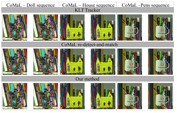
This is a controlled setting where we evaluate CoMaL redetect-and-match, KLT and our tracking algorithms on the dataset provided by the authors of the CoMaL Detector [26]. Tracking of feature points at the boundaries is difficult in this dataset due to a large texture in the background of the objects, leading to a large variation in the support region of the boundary points. The dataset provides images for the background in order to perform background subtraction and obtain the foreground pixels. Thus we can compute the boundary regions which enables the evaluation the different methods on the boundary and non-boundary regions separately. Some qualitative results are shown in Figure 8 while Table 1 shows some quantitative results. Our tracking algorithm clearly outperforms KLT on the boundary regions as expected. The background portion of the support region changes very frequently in the CoMaL dataset, due to which KLT cannot track effectively. However, the tracker slightly underperforms compared to CoMaL re-detect-and-match on the boundary regions. We improve over the re-detect-and-match in the interior regions as expected. We also observe a slight improvement over KLT in the interior regions possibly because of the more stable nature of the level line approach compared to a patch matching approach.
| Sequence | Doll | Hero | House | Toy | Pens | Race-car |
| Method | Boundary Region | |||||
| CoMaL TD | 80.6/1.0 | 76.8/1.0 | 53.0/1.0 | 55.5/1.0 | 54.1/1.0 | 85.7/1.0 |
| KLT | 43.2/1.0 | 40.5/1.0 | 32.6/1.0 | 28.5/1.0 | 22.4/1.0 | 40.1/1.0 |
| Ours | 68.5/1.0 | 72.2/1.0 | 40.0/1.0 | 34.1/1.0 | 48.7/1.0 | 73.1/1.0 |
| Method | Non-Boundary Region | |||||
| CoMaL TD | 143.0/1.0 | 201.8/1.0 | 91.7/0.9 | 108.8/1.0 | 70.3/1.0 | 138.3/1.0 |
| KLT | 138.6/1.0 | 156.2/1.0 | 178.5/0.9 | 95.3/1.0 | 71.9/1.0 | 136.0/1.0 |
| Ours | 203.6/1.0 | 254.3/1.0 | 138.2/0.9 | 142.5/1.0 | 104.9/1.0 | 205.2/1.0 |
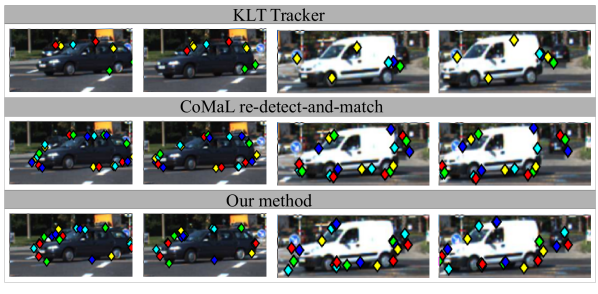
4.3.2 Vehicle Tracking
| Sequence | CarA | CarC | CarF | CarG |
|---|---|---|---|---|
| Method | Boundary Region | |||
| KLT | 48.4/0.7 | 52.9/0.8 | 26.2/0.9 | 51.7/0.7 |
| CoMaL TBD | 76.0/0.8 | 86.2/0.8 | 33.9/0.9 | 64.2/0.7 |
| Ours | 75.9/0.7 | 91.0/0.8 | 51.8/0.9 | 71.7/0.7 |
| Method | Non-Boundary Region | |||
| KLT | 174.0/0.7 | 263.8/0.8 | 97.9/0.9 | 168.0/0.7 |
| CoMaL TBD | 127.2/0.7 | 204.0/0.8 | 33.9/0.9 | 148.3/0.7 |
| Ours | 193.7/0.7 | 326.7/0.8 | 141.2/0.9 | 225.9/0.7 |
| Method | Overall | |||
| KLT | 222.4/0.7 | 316.8/0.8 | 124.2/0.9 | 219.7/0.7 |
| CoMaL TBD | 203.2/0.7 | 290.1/0.8 | 64.9/0.9 | 212.6/0.7 |
| Ours | 270.4/0.7 | 417.6/0.8 | 193.0/0.9 | 297.6/0.7 |
Next, we evaluate our algorithm on the vehicle tracking problem. Point tracking has been applied extensively for this application [14, 23, 25, 29, 33, 35], where KLT [15] is the most common choice [33, 35, 32, 23, 25]. Vehicle tracking has become increasingly important with the impending advent of autonomous vehicles, traffic surveillance systems, etc. Since it is possible for vehicles to have uniform surfaces hindering the use of corners, edges, etc. in the interior of the vehicle, it is important to fully utilize the boundary information of the vehicle for optimum tracking and hence, the performance of the point trackers at the boundaries is important (A recent crash of a Tesla car due to a homogeneous tractor trailer is a relevant case). Also, while learning-based vehicle tracking algorithms have been fairly successful at the task of object tracking recently, these algorithms might fail when the object is not fully visible in the image or if an object or variations in pose of objects which were unseen in the training data are observed in the scene. This necessitates augmentation of such learning-based approaches with conventional feature point-based approaches in order to make the systems more robust. To test the efficacy of our tracker, we evaluate the performance on 4 sequences of the KITTI dataset [12]. The remaining sequences had relatively low frame-rates which hinder the performance of any point based tracking algorithm, so we do not report results on them. In the KITTI dataset, video sequences are taken from moving vehicles and present realistic scenarios for autonomous driving. The results obtained are shown in Table 2. In order to provide a comparison on the boundary and interior regions, we segmented the vehicles in the 4 sequences by manually providing interactive inputs to the GrabCut [28] algorithm. We obtained a segmentation for all the frames of the CarA sequence, and only 100 consecutive frames in CarC, CarF and CarG sequences, as this was a manual effort and hence time-consuming. Our tracking method outperforms KLT by a significant margin on the boundaries in all the four sequences. It also slightly improves over CoMaL re-detect-and-match on the boundaries as well as the interior. Thus, our algorithm works as expected in the realistic scenario of autonomous driving as presented by the KITTI dataset. Some qualitative results are provided in Figure 9.
| Sequence | Frame rate | MOT-02 | MOT-04 | MOT-05 | MOT-09 | MOT-10 | MOT-11 | MOT-13 |
|---|---|---|---|---|---|---|---|---|
| KLT | 91.6/0.6 | 102.0/0.8 | 715.9/0.7 | 64.5/0.8 | 48.8/0.7 | 531.0/0.8 | 226.7/0.6 | |
| 97.1/0.6 | 101.8/0.8 | 311.0/0.7 | 45.9/0.8 | 22.4/0.7 | 433.5/0.8 | 184.3/0.6 | ||
| 81.9/0.6 | 92.1/0.8 | 363.4/0.6 | 15.8/0.8 | 7.1/0.7 | 185.8/0.8 | 132.4/0.6 | ||
| Ours | 94.8/0.6 | 191.0/0.8 | 656.6/0.7 | 136.0/0.8 | 83.5/0.8 | 621.5/0.8 | 254.2/0.6 | |
| 83.2/0.6 | 188.7/0.8 | 443.0/0.7 | 97.4/0.8 | 65.7/0.8 | 495.7/0.8 | 207.8/0.6 | ||
| 67.0/0.6 | 175.6/0.8 | 396.3/0.6 | 55.3/0.8 | 44.7/0.8 | 361.5/0.8 | 153.7/0.6 |
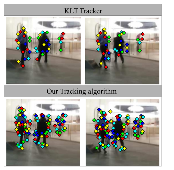
4.3.3 Human Tracking
Point Tracking has been used extensively in the Action Recognition community where KLT is again the most popular choice for obtaining point trajectory-based features [38, 18, 17, 37, 34]. We show the efficacy of our tracker for the domain of Human Tracking. Results are shown on the MOT 2016 challenge training video sequences. The dataset provides ground truth trajectories for the bounding boxes of humans in the scene in the training set, which we use to generate the ground truth for point tracking. The sequences are challenging because the cameras are moving and include crowded scenes such as shopping malls, busy streets, etc. Since the frame-rate of the provided sequences was high, we show variations in the performance of our tracking algorithm as the frame rate reduces. For KLT, this can be more of a challenge as it uses a gradient-descent approach. For us, this can also reduce the performance since one will have to search in a larger window, which can increase the running time, apart from increasing the chances of a wrong match. As outlined in Section 4.2, we generate the ground truth by assuming that the relative location of the points w.r.t. the annotated bounding box remains the same. Some qualitative results are shown in Figure 10 while the quantitative results are shown in Table 3. While we show KLT’s variation in performance with the frame rates, it may not be a fair comparison as the KLT tracker was not designed to work for low frame rates. Our algorithm outperforms KLT at the original frame rate on six out of the seven sequences. We can also observe that our performance does not drop significantly as the frame rate decreases, which is expected because of our robust two-stage tracking, although we had to increase the search window in the case of lower frame rates due to a higher object motion. Due to unavailability of segmentation information and infeasibility of annotating the dataset, we report only the overall results and do not have the boundary and non-boundary classification of the points.
5 Conclusions and Future Work
We have proposed an accurate tracking algorithm for tracking Feature points on the Object Boundaries. We track the CoMaL Feature points which are shown to be superior for detection and matching on object boundaries. This is achieved by first tracking the level line segment associated with the corner by matching it with level lines obtained in the next frame using MSER detection. The level lines are initially matched using the Hierarchical Chamfer Matching Algorithm to filter out poor matches, and the shortlisted matches are then verified using Part SSD matching to obtain the best match. Tracking results on three different scenarios of Object Tracking, Vehicle Tracking and Human Tracking show significant improvement in performance at the object boundaries when compared to the current state-of-the-art in tracking, i.e. KLT, and also an overall improvement in performance compared to the CoMaL re-detect-and-match framework proposed earlier. It is also more efficient than the CoMaL re-detect-and-match framework.
Future work includes development of a real-time implementation of the tracker, possibly by utilization of GPUs.
References
- [1] A. Akbarzadeh, J.-M. Frahm, P. Mordohai, B. Clipp, C. Engels, D. Gallup, P. Merrell, M. Phelps, S. Sinha, B. Talton, et al. Towards urban 3d reconstruction from video. In 3D Data Processing, Visualization, and Transmission, Third International Symposium on, pages 1–8. IEEE, 2006.
- [2] R. Almomani and M. Dong. Segtrack: A novel tracking system with improved object segmentation. In 2013 IEEE International Conference on Image Processing, pages 3939–3943. IEEE, 2013.
- [3] S. Baker and I. Matthews. Equivalence and efficiency of image alignment algorithms. In Computer Vision and Pattern Recognition, 2001. CVPR 2001. Proceedings of the 2001 IEEE Computer Society Conference on, volume 1, pages I–1090. IEEE, 2001.
- [4] S. Baker and I. Matthews. Lucas-kanade 20 years on: A unifying framework. International journal of computer vision, 56(3):221–255, 2004.
- [5] Y. Bok, Y. Hwang, and I. S. Kweon. Accurate motion estimation and high-precision 3d reconstruction by sensor fusion. In Proceedings 2007 IEEE International Conference on Robotics and Automation, pages 4721–4726. IEEE, 2007.
- [6] D. S. Bolme, J. R. Beveridge, B. A. Draper, and Y. M. Lui. Visual object tracking using adaptive correlation filters. In Computer Vision and Pattern Recognition (CVPR), 2010 IEEE Conference on, pages 2544–2550. IEEE, 2010.
- [7] G. Borgefors. Hierarchical chamfer matching: A parametric edge matching algorithm. IEEE Transactions on pattern analysis and machine intelligence, 10(6):849–865, 1988.
- [8] X. Cao, J. Lan, P. Yan, and X. Li. Klt feature based vehicle detection and tracking in airborne videos. In Image and Graphics (ICIG), 2011 Sixth International Conference on, pages 673–678. IEEE, 2011.
- [9] D. Chen, Z. Yuan, Y. Wu, G. Zhang, and N. Zheng. Constructing adaptive complex cells for robust visual tracking. In Proceedings of the IEEE International Conference on Computer Vision, pages 1113–1120, 2013.
- [10] N. Dalal and B. Triggs. Histograms of oriented gradients for human detection. In 2005 IEEE Computer Society Conference on Computer Vision and Pattern Recognition (CVPR’05), volume 1, pages 886–893. IEEE, 2005.
- [11] M. Danelljan, A. Robinson, F. S. Khan, and M. Felsberg. Beyond correlation filters: learning continuous convolution operators for visual tracking. In European Conference on Computer Vision, pages 472–488. Springer, 2016.
- [12] A. Geiger, P. Lenz, and R. Urtasun. Are we ready for autonomous driving? the kitti vision benchmark suite. In Conference on Computer Vision and Pattern Recognition (CVPR), 2012.
- [13] C. Harris and M. Stephens. A combined corner and edge detector. In In Alvey vision conference, page 50, 1988.
- [14] J.-P. Jodoin, G.-A. Bilodeau, and N. Saunier. Urban tracker: Multiple object tracking in urban mixed traffic. In IEEE Winter Conference on Applications of Computer Vision, pages 885–892. IEEE, 2014.
- [15] B. D. Lucas, T. Kanade, et al. An iterative image registration technique with an application to stereo vision. 1981.
- [16] J. Matas, O. Chum, M. Urban, and T. Pajdla. Robust wide-baseline stereo from maximally stable extremal regions. Image and vision computing, 22(10):761–767, 2004.
- [17] P. Matikainen, M. Hebert, and R. Sukthankar. Trajectons: Action recognition through the motion analysis of tracked features. In Computer Vision Workshops (ICCV Workshops), 2009 IEEE 12th International Conference on, pages 514–521. IEEE, 2009.
- [18] R. Messing, C. Pal, and H. Kautz. Activity recognition using the velocity histories of tracked keypoints. In 2009 IEEE 12th international conference on computer vision, pages 104–111. IEEE, 2009.
- [19] K. Mikolajczyk and C. Schmid. Comparison of affine-invariant local detectors and descriptors. In Signal Processing Conference, 2004 12th European, pages 1729–1732. IEEE, 2004.
- [20] K. Mikolajczyk and C. Schmid. Scale & affine invariant interest point detectors. International journal of computer vision, 60(1):63–86, 2004.
- [21] K. Mikolajczyk, T. Tuytelaars, C. Schmid, A. Zisserman, J. Matas, F. Schaffalitzky, T. Kadir, and L. Van Gool. A comparison of affine region detectors. International journal of computer vision, 65(1-2):43–72, 2005.
- [22] K. Mikolajczyk, A. Zisserman, and C. Schmid. Shape recognition with edge-based features. In British Machine Vision Conference (BMVC’03), volume 2, pages 779–788. The British Machine Vision Association, 2003.
- [23] D. Nistér, O. Naroditsky, and J. Bergen. Visual odometry. In Computer Vision and Pattern Recognition, 2004. CVPR 2004. Proceedings of the 2004 IEEE Computer Society Conference on, volume 1, pages I–652. IEEE, 2004.
- [24] S. Oron, A. Bar-Hille, and S. Avidan. Extended lucas-kanade tracking. In European Conference on Computer Vision, pages 142–156. Springer, 2014.
- [25] M. Pollefeys, D. Nistér, J.-M. Frahm, A. Akbarzadeh, P. Mordohai, B. Clipp, C. Engels, D. Gallup, S.-J. Kim, P. Merrell, et al. Detailed real-time urban 3d reconstruction from video. International Journal of Computer Vision, 78(2-3):143–167, 2008.
- [26] S. K. Ravindran and A. Mittal. Comal: Good features to match on object boundaries. In The IEEE Conference on Computer Vision and Pattern Recognition (CVPR), June 2016.
- [27] E. Rosten and T. Drummond. Fusing points and lines for high performance tracking. In IEEE International Conference on Computer Vision, volume 2, pages 1508–1511, October 2005.
- [28] C. Rother, V. Kolmogorov, and A. Blake. Grabcut: Interactive foreground extraction using iterated graph cuts. In ACM transactions on graphics (TOG), volume 23, pages 309–314. ACM, 2004.
- [29] K. Sakurada, T. Okatani, and K. Deguchi. Detecting changes in 3d structure of a scene from multi-view images captured by a vehicle-mounted camera. In Proceedings of the IEEE Conference on Computer Vision and Pattern Recognition, pages 137–144, 2013.
- [30] J. Shi and C. Tomasi. Good features to track. In Computer Vision and Pattern Recognition, 1994. Proceedings CVPR’94., 1994 IEEE Computer Society Conference on, pages 593–600. IEEE, 1994.
- [31] S. N. Sinha, J.-M. Frahm, M. Pollefeys, and Y. Genc. Gpu-based video feature tracking and matching.
- [32] S. N. Sinha, J.-M. Frahm, M. Pollefeys, and Y. Genc. Feature tracking and matching in video using programmable graphics hardware. Machine Vision and Applications, 22(1):207–217, 2011.
- [33] H.-S. Song, S.-N. Lu, X. Ma, Y. Yang, X.-Q. Liu, and P. Zhang. Vehicle behavior analysis using target motion trajectories. IEEE Transactions on Vehicular Technology, 63(8):3580–3591, 2014.
- [34] J. Sun, Y. Mu, S. Yan, and L.-F. Cheong. Activity recognition using dense long-duration trajectories. In Multimedia and Expo (ICME), 2010 IEEE International Conference on, pages 322–327. IEEE, 2010.
- [35] S. Tanathong and I. Lee. Translation-based klt tracker under severe camera rotation using gps/ins data. IEEE Geoscience and remote sensing letters, 11(1):64–68, 2014.
- [36] C. Tomasi and T. Kanade. Detection and tracking of point features. School of Computer Science, Carnegie Mellon Univ. Pittsburgh, 1991.
- [37] H. Uemura, S. Ishikawa, and K. Mikolajczyk. Feature tracking and motion compensation for action recognition. In BMVC, pages 1–10, 2008.
- [38] H. Wang, A. Kläser, C. Schmid, and C.-L. Liu. Action recognition by dense trajectories. In Computer Vision and Pattern Recognition (CVPR), 2011 IEEE Conference on, pages 3169–3176. IEEE, 2011.
- [39] C. Zach, D. Gallup, and J.-M. Frahm. Fast gain-adaptive klt tracking on the gpu. In Computer Vision and Pattern Recognition Workshops, 2008. CVPRW’08. IEEE Computer Society Conference on, pages 1–7. IEEE, 2008.