Double-zero-index structural waveguides
Abstract
We report on the theoretical and experimental realization of a double-zero-index elastic waveguide and on the corresponding acoustic cloacking and supercoupling effects. The proposed waveguide uses geometric tapers in order to induce Dirac-like cones at due to accidental degeneracy. The nature of the degeneracy is explored by a perturbation method adapted to thin structural waveguides. Results confirm the linear nature of the dispersion around the degeneracy and the possibility to map the material to effective medium properties. Effective parameters, numerically extracted using boundary medium theory, confirm that the phononic waveguide maps into a double zero index material. Numerical and experimental results confirm the expected cloacking and supecoupling effects typical of zero index materials.
I Introduction
The concept of acoustic metamaterials Cui et al. (2009) has rapidly emerged as a powerful alternative to design materials and structures exhibiting unexpected dynamic properties typically not achievable in natural materials. In less than two decades, this concept has allowed a drastic expansion of the materials design space enabling novel applications involving acoustic wave management and control. Properties such as acoustic bandgaps Liu et al. (2000); Yang et al. (2002); Sanchis-Alepuz et al. (2007); Garcia-Pablos et al. (2000); Vasseur et al. (2001), focusing Zhang et al. (2009); Aydin et al. (2005); Ma and Liu (2010); Lippens (2009); Baz (2009); Abasi et al. (2011); Li et al. (2012); Zhu and Semperlotti (2013), collimation Jagoszewski (1984); He et al. (2009); Kaya et al. (2012); Mei et al. (2008), sub-wavelength resolution Zhang et al. (2010); Wiltshire et al. (2006); Belov and Hao (2006); Li et al. (2009); Semperlotti and Zhu (2014), and negative refraction Morvan et al. (2010); Pierre et al. (2010), have been discovered and studied in depth. More recently, researchers have shown a rather new and exciting property of these materials consisting in their ability to achieve near-zero effective parameters. This class of materials was first formulated for electromagnetic waves where epsilon-near-zero (ENZ), mu-near-zero (MNZ), and epsilon-and-mu-near-zero (EMNZ) properties were first obtained. Applications included antenna designs with high directivity Alù et al. (2007); Enoch et al. (2002) and enhanced radiation efficiency Alu et al. (2006); Soric et al. (2013), as well as the realization of unconventional tunneling of electromagnetic energy within ultra-thin subwavelength channels or bends Ziolkowski (2004); Silveirinha and Engheta (2006, 2007). Among the most peculiar characteristics of these materials, we mention the independence of the phase from the propagation distance. This means that a wave entering a double-zero material emerges on the other side having the exact same phase as the input. In addition, double-zero materials are also characterized by a high level of transmissibility, ideally acting as a non-reflective waveguide even in presence of sharp impedance discontinuities.
While materials with near-zero permittivity are available in nature (e.g. some noble metals, doped semiconductors Adams et al. (2011), polar dielectrics Silveirinha and Engheta (2009), transparent conducting oxide (TCOs) Naik et al. (2011)), in acoustics near-zero density and elastic compliance must be achieved as effective quantities by leveraging the local dynamic response of the medium. In the past few years, some acoustic metamaterials were reported to exhibit single zero effective parameters, such as near zero density Fleury and Alù (2013); Zheng et al. (2014); Xu et al. (2015). We note that this behavior is the exact counterpart to single zero electromagnatic materials, such as the ENZ. Although these materials offered good control on the phase, they suffered from low-transmissibility due to an intrinsic impedance mismatch between the host and the zero effective density medium. Electromagnetic double zero materials were designed specifically to alleviate this limitation on the transmission properties. However, designing acoustic media with double zero effective properties is not a trivial task given that, as previously mentioned, they are not readily available in nature.
Recent studies on photonic and phononic crystals Liu et al. (2011); Wu et al. (2011); Liu et al. (0213); Yan Li and Mei (2014); Yang Li and Mazur (2013); Parikshit Moitra and Valentine (2015); Wu and Mei (1601); Ashraf and Faryad (2016, 2015) revealed that when a Dirac-like Cone (DC) can be obtained at the center of the Brillouin zone, such lattice can be mapped into a double-zero refractive index material. This observation has drastically extended the possibility to design materials having near-zero effective properties. Nevertheless, while different applications of this basic concept were explored in photonics and phononics, there has been very little research targeting the implementation of these effective material properties in solids Liu et al. (2016, 2011). The research on elastic phononic waveguides has been lagging behind even more and it currently counts no attempt of designing zero-index properties. In addition, the experimental implementation and validation of zero-index elastic media has not been reported in the scientific literature mostly due to the complexities associated with their design and fabrication.
In the present study, we report on the theoretical, numerical, and experimental realization of a structural phononic waveguide exhibiting double-zero-index-material (DZIM) behavior and capable of achieving acoustic cloaking and supercoupling.
The proposed design builds upon a class of metamaterials recently introduced by the authors Zhu and Semperlotti (2015, 2016, 2017) and based on geometric tapers realized in a single-material system. The specific design employed in this study can be thought as an equivalent locally-resonant unit where an internal resonating core is embedded within a more compliant medium (i.e. the taper).
Geometrically tapered metamaterials Zhu and Semperlotti (2015) exhibit Dirac-like Cones (DC) at the center of the Brillouin zone ( point) that are the result of accidental degeneracies Mei et al. (2012). In other terms, the degeneracy is induced by the specific combination of the geometric parameters of the tapers and it is not protected by the underlying lattice structure (like, as an example, in graphene). The bands emanating from the three-fold degenerate point (the Dirac-like point) exhibit isotropic linear dispersion. We will show that these properties are the foundation that allows achieving double-zero effective properties in this class of materials. In particular, we will show that in the neighborhood of this degenerate point our waveguide exhibits simultaneous zero mass density and and zero reciprocal shear modulus (or, equivalently, infinite shear modulus).
II Results
II.1 Double-zero index waveguide via geometric tailoring
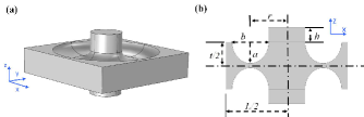
The proposed phononic waveguide employs a tapered unit cell in a square lattice configuration ( symmetry). The unit cell consists of a square plate having an embedded elliptic torus-like taper and a (resonating) center mass. The unit is also symmetric with respect to the plate mid-plane (see Fig.1). The cross-section of the unit is shown in Fig.1b and shows the main geometric parameters where is the thickness of the element, is the lattice constant, and are the lengths of the minor and major axes of the ellipse, is the radius of the torus, and is the thickness of center mass. The unit was made out of aluminum with mass density , Young’s modulus GPa, and the Poisson’s ratio .
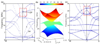
The dispersion relations for the proposed system were calculated using a commercial finite element solver (Comsol Multiphysics). Given the finite dimension of the unit cell in the thickness direction the dispersion curves are composed by symmetric (S), anti-symmetric (A), and shear horizontal (SH) guided Lamb modes. By using a proper selection of the geometric parameters (specifically m, m, m, m, m and m), the band structure of the waveguide was tuned to exhibit a three-fold degenerate point (the Dirac-like Point, DP) at kHz and (Fig.2a). Note that the branches emanating from the degenerate point are isotropic and linear and form two cones touching on their vertices at the DP (Fig. 2b). The cones are made of modes having non-zero but constant group velocity and are intersected by an flat band at the DP.
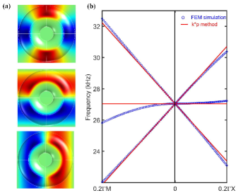
The Dirac-like cone is the result of an accidental degeneracy, which can be confirmed by slightly perturbing the geometric parameters. By perturbing the torus-like taper (from 0.0039 to 0.0035) the cones separate (see Fig.2c) and the triple degenerate point splits into a non-degenerate and a doubly degenerate band. The corresponding eigenstates of the three degenerate modes are provided in Fig.3a which shows, from top to bottom, the lower cone, the flat band, and the upper cone.
II.2 Analysis of the Dirac-like cones
To further understand the origin of the Dirac-like dispersion, we extended the method (well-known in electronic applications) to analyze our phononic system. This method was recently adopted by MeiMei et al. (2012) to analyze the Dirac and Dirac-like cones in two-dimensional phononic and photonic crystals.
Our system is described by the Navier’s equations with traction-free boundary conditions on the top and bottom surfaces of the waveguide. Imposing such boundary conditions when in presence of tapers creates non-trivial complexities due to the changing direction of the unit vector normal to the tapered surface. In order to avoid this issue, we resorted to an approach previously used to extend the three-dimensional plane wave expansion method to 2D phononic waveguides Hou and Assouar (2008); Zhu and Semperlotti (2015). The details of the method are provided in Supplementary. According to this method, the 2D waveguide is part of a layered three-dimensional periodic system that is constructed by alternating the waveguide and vacuum layers along the thickness direction. The resulting three-dimensional periodic medium can then be modeled as a layered bulk material according to the Navier’s equations. The solution of the homogeneous problem provides the dispersions for the medium. Note that the use of the vacuum layer ensures that the periodic images of the waveguide along the thickness direction are dynamically decoupled from each other, therefore simply resulting in repeated roots in the dispersion calculation.
We can then write the general form of the Navier’s equations for an inhomogeneous bulk medium as,
| (1) | ||||
here is the particle displacement vector, is the local density, and are the local Lamé constants, which are all functions of the spatial variables. To apply the method to Eqns.(1), we write the Bloch functions in the vicinity of the point as linear combinations of the three degenerate states. After substituting these functions into Eqn.(1), applying periodic boundary conditions, and collecting only the linear order terms in we obtain,
| (2) |
where denotes the band index at the Bloch wave vector , and P is the reduced Hamiltonian matrix with elements , that represent the coupling strength between the degenerate state and at the point. The matrix element can be calculated as,
| (3) |
After evaluating Eqn.(3) numerically, the reduced Hamiltonian matrix is given by,
| (4) |
Note that , , and ; these properties are required to guarantee the isotropy of the cones. By substituting Eqn.(4) into Eqn.(1), we get the dispersion relations of the modes contributing to the Dirac-like cone,
| (5) |
where we have approximated the term as . Obviously the first result in Eqn.(5) corresponds to the flat band while the remaining two signed values correspond to the linear dispersion associated with the cones. Note that these results do not depend on the wave vector direction thus confirming the isotropy of the linear dispersion. Equations (5) can be plot together with the numerically obtained dispersion relations (Fig.3b) in order to illustrate the good agreement between the method and the full field numerical results. It can be seen from Eqn.(4) that the linear dispersion was determined by the non-diagonal element of the matrix. This term represents the strength of the coupling between the degenerate states, and indicates that the frequency repulsion effect gives rise to the Dirac-like Cones.
II.3 Effective medium properties
An interesting feature of the Dirac-like cone is that, under certain conditions, it can be mapped to an effective medium. Reducing the dynamic properties to effective medium properties allows a very clear characterization of the double zero properties. Note that although the selected DP has a relatively high frequency (the wavelength in the flat plate is about 1.25a), we employed the boundary effective medium theory Yun Lai and Zhang (2011) (see Supplementary material) to obtain the effective material parameters. It has been argued Craster et al. (2010, 2011) that, for periodic media, the effective medium theory Ding et al. (2007); Wu et al. (2007) is still valid at around the standing wave frequency even if the frequency belongs to the short wavelength regime. From a more empirical perspective, we will also show that the use of the effective medium description matches well the finite element model predictions.
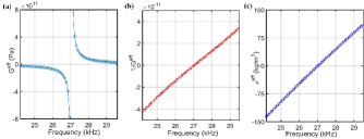
By using the boundary effective medium theory Yun Lai and Zhang (2011), we obtained the effective shear modulus and the effective mass density as function of frequency in the range around the Dirac-like point (Fig.4a and c). It can be seen that below the DP, the proposed metamaterial design acts as a double negative material while above the DP it acts as a double positive material. Similarly, the calculation of the reciprocal effective shear modulus (Fig.4b) shows that both and vary linearly and become zero simultaneously as the frequency crosses the Dirac-like point. These results suggest that the proposed metamaterial should exhibit propagation properties consistent with a double-zero-index material. In particular, we expect that acoustic waves traveling through the medium at the DP frequency should not experience any spatial phase change.
II.4 Full field numerical analyses
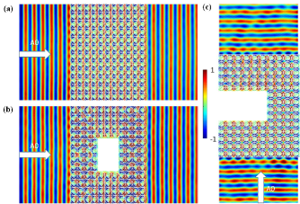
In order to validate the theoretical predictions formulated above, we built a numerical model of an elastic waveguide made out of the proposed double-zero-index material. The basic test structure consisted in a flat plate with a lattice of torus-like tapers embedded in the center (Fig.5a and b). Left and right boundaries were treated with perfectly matched layers (not shown) to avoid reflections, while top and bottom boundaries were treated with periodic conditions in order to simulate an infinite plate. The zero-index material slab was excited from the left by a planar wave at kHz and normal incidence. The resulting wave field (Fig.5a) indicated that no phase change occurred inside the metamaterial slab and nearly full transmission was achieved due to the zero-refractive-index and the matched impedance with the flat plate. These peculiar transmission properties were tested to show the ability to achieve cloaking and supercoupling in structural waveguides.
To illustrate the cloaking capability we embedded an object (represented by a through-hole opening units in size) within the DZIM metamaterial. The opening had clamped boundary conditions. The remaining conditions were unchanged with respect to the case discussed above. The numerical results (Fig.5b) show that the wave emerges on the opposite side of the slab being completely unaffected. Comparing these results with Fig.5a, we see that the acoustic field downstream of the object does not carry any information about the object itself therefore confirming the cloaking capability of the medium.
In a similar way, we tested the transmission performance of a U-shaped waveguide channel. The change in cross section was operated within the zero-index slab by shrinking the middle section from 10 to 4 units. Similarly to the cloaking case, clamped boundary conditions were imposed on all the walls of the U-shaped waveguide while the remaining boundaries were left free. In addition, perfectly matched layers were used on the top and bottom surfaces to absorb the outgoing waves and eliminate reflections. We observe that the incident plane wave ( mode at kHz) propagated through the U-shaped channel completely unaffected picking up only a minor phase distortion. These results confirm the ability of the proposed design to create supercoupling effects in structural waveguides.
II.5 Experimental Results
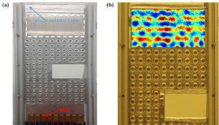
We performed an experimental investigation in order to validate the concept of DZIM structural waveguide. We selected the supercoupling case for testing because it is the most challenging condition to achieve and therefore the most representative of the actual performance. To facilitate fabrication and testing, we rescaled the structure by reducing the plate thickness to mm and the unit cell dimension to half of the original size. The rescaling resulted in a Dirac-like point at kHz. The test sample was fabricated with extended edges along the U-Shaped waveguide channel in order to be able to enforce the boundary conditions. For simplicity, instead of creating a complex setup to impose the clamped conditions used in the simulation results (Fig.5c), we decided to treat these edges of the U-section with viscoelastic damping material while clamping the remaining edges. Numerical simulations were performed to show that this selection of boundary conditions ensured similar transport behavior to those used in the previous simulations (see supplementary material).
The torus-like tapers were CNC machined from an initially flat aluminum plate while the center masses were cut from aluminum bars and successively glued on the taper. The experimental sample was mounted vertically in an aluminum frame and viscoelastic tape was applied on the top and bottom edges in order to minimize reflections from the boundaries. An array of Micro Fiber Composites (MFC) patches (Fig.6a) was surface bonded on the plate and simultaneously actuated to generate a quasi planar incident wave. The excitation signal was a 50-count wave burst with a kHz center frequency. The out-of-plane response of the plate after the DZIM slab (marked by the dashed white box in Fig.6a) was acquired using a Polytec PSV-500 laser scanning vibrometer. Figure 6b shows the measured out-of-plane velocity field at a given time instant. The measurements clearly indicate that the wave passes through the U-shaped waveguide channel preserving its planar wavefront. Note that the finite nature of the section before and after the metamaterial slab produces reflections that alter the structure of the transmitted wavefront. Despite the reverberation effect due to the finite boundaries, the planar nature of the transmitted wave fields is still well identifiable. These results confirm the theoretical and numerical predictions and the overall behavior of the double-zero-index waveguide.
III Conclusions
We have presented and experimentally demonstrated the design of a double zero index structural waveguide. The design leverages the use of locally-resonant geometric tapers that are used as fundamental unit cells to achieve and tune Dirac-like dispersion at the center of the Brillouin zone. We showed, both by theoretical and numerical methods, that the material can be mapped to a double zero effective medium when excited in the neighborhood of the Dirac-like point. Full field numerical simulations showed that this material can be used to achieve cloaking and supercoupling in elastic waveguides. Both theoretical and numerical results were confirmed by experimental measurements that validated the design and provided conclusive evidence that double zero properties can be successfully achieved in solids.
IV Acknowledgments
The authors gratefully acknowledge the financial support of the Air Force Office of Scientific Research under the grant YIP FA9550-15-1-0133.
References
- Cui et al. (2009) T. Cui, D. Smith, and R. Liu, Metamaterials: Theory, Design, and Applications (Springer, 2009).
- Liu et al. (2000) Z. Liu, X. Zhang, Y. Mao, Y. Zhu, Z. Yang, C. Chan, and P. Sheng, Science 289, 1734 (2000).
- Yang et al. (2002) S. Yang, J. Page, Z. Liu, M. Cowan, C. Chan, and P. Sheng, Phys. Rev. Lett. 88, 1043011 (2002).
- Sanchis-Alepuz et al. (2007) H. Sanchis-Alepuz, Y. A. Kosevich, and J. Sanchez-Dehesa, Phys. Rev. Lett. 98 (2007).
- Garcia-Pablos et al. (2000) D. Garcia-Pablos, M. Sigalas, F. M. de Espinosa, M. Torres, M. Kafesaki, and N. Garcia, Phys. Rev. Lett. 84, 4349 (2000).
- Vasseur et al. (2001) J. Vasseur, P. Deymier, B. Chenni, B. Djafari-Rouhani, L. Dobrzynski, and D. Prevost, Phys. Rev. Lett. 86, 3012 (2001).
- Zhang et al. (2009) S. Zhang, L. Yin, and N. Fang, Physical Review Letters 102 (2009).
- Aydin et al. (2005) K. Aydin, I. Bulu, and E. Ozbay, Optics Express 13, 8753 (2005).
- Ma and Liu (2010) C. Ma and Z. Liu, Optics Express 18, 4838 (2010).
- Lippens (2009) D. Lippens, Comptes Rendus - Physique 10, 400 (2009).
- Baz (2009) A. Baz, Proceedings of the ASME Conference on Smart Materials, Adaptive Structures and Intelligent Systems 2009 vol.1, 259 (2009).
- Abasi et al. (2011) R. Abasi, L. Markley, and G. Eleftheriades, Journal of the Acoustical Society of America 130, 405 (2011).
- Li et al. (2012) Y. Li, B. Liang, X. Tao, X. feng Zhu, X. ye Zou, and J. chun Cheng, Applied Physics Letters 101, 233508(5 pp.) (2012).
- Zhu and Semperlotti (2013) H. Zhu and F. Semperlotti, AIP Advances 3, 092121 (2013).
- Jagoszewski (1984) E. Jagoszewski, Optik 67, 137 (1984).
- He et al. (2009) Z. He, Y. Heng, S. Peng, Y. Ding, M. Ke, and Z. Liu, Journal of Applied Physics 105, 116105 (2009).
- Kaya et al. (2012) O. Kaya, A. Cicek, and B. Ulug, Journal of Physics D: Applied Physics 45, 365101 (7 pp.) (2012).
- Mei et al. (2008) J. Mei, B. Hou, M. Ke, S. Peng, H. Jia, Z. Liu, J. Shi, W. Wen, and P. Sheng, Applied Physics Letters 92 (2008).
- Zhang et al. (2010) Y. Zhang, D. Zhang, and M. Fiddy, 2010 Photonics Global Conference (PGC 2010) , 4 pp. (2010).
- Wiltshire et al. (2006) M. Wiltshire, J. Pendry, and J. Hajnal, Journal of Physics: Condensed Matter 18, 315 (2006).
- Belov and Hao (2006) P. Belov and Y. Hao, Optics InfoBase Conference Papers (2006).
- Li et al. (2009) J. Li, L. Fok, X. Yin, G. Bartal, and X. Zhang, Nature Materials 8, 931 (2009).
- Semperlotti and Zhu (2014) F. Semperlotti and H. Zhu, Journal of Applied Physics 116, 054906 (2014).
- Morvan et al. (2010) B. Morvan, A. Tinel, A.-C. Hladky-Hennion, J. Vasseur, and B. Dubus, Appl. Phys. Lett. 96, 101905 (3 pp.) (2010).
- Pierre et al. (2010) J. Pierre, O. Boyko, L. Belliard, J. Vasseur, and B. Bonello, Appl. Phys. Lett. 97 (2010).
- Alù et al. (2007) A. Alù, M. G. Silveirinha, A. Salandrino, and N. Engheta, Phys. Rev. B 75, 155410 (2007).
- Enoch et al. (2002) S. Enoch, G. Tayeb, P. Sabouroux, N. Guérin, and P. Vincent, Phys. Rev. Lett. 89, 213902 (2002).
- Alu et al. (2006) A. Alu, F. Bilotti, N. Engheta, and L. Vegni, IEEE Transactions on Antennas and Propagation 54, 1632 (2006).
- Soric et al. (2013) J. C. Soric, N. Engheta, S. Maci, and A. Alu, IEEE Transactions on Antennas and Propagation 61 (2013).
- Ziolkowski (2004) R. W. Ziolkowski, Phys. Rev. E 70, 046608 (2004).
- Silveirinha and Engheta (2006) M. Silveirinha and N. Engheta, Phys. Rev. Lett. 97, 157403 (2006).
- Silveirinha and Engheta (2007) M. Silveirinha and N. Engheta, Phys. Rev. B 75, 075119 (2007).
- Adams et al. (2011) D. C. Adams, S. Inampudi, T. Ribaudo, D. Slocum, S. Vangala, N. A. Kuhta, W. D. Goodhue, V. A. Podolskiy, and D. Wasserman, Phys. Rev. Lett. 107, 133901 (2011).
- Silveirinha and Engheta (2009) M. G. Silveirinha and N. Engheta, Phys. Rev. Lett. 102, 103902 (2009).
- Naik et al. (2011) G. V. Naik, J. Kim, and A. Boltasseva, Opt. Mater. Express 1, 1090 (2011).
- Fleury and Alù (2013) R. Fleury and A. Alù, Phys. Rev. Lett. 111, 055501 (2013).
- Zheng et al. (2014) L.-Y. Zheng, Y. Wu, X. Ni, Z.-G. Chen, M.-H. Lu, and Y.-F. Chen, Applied Physics Letters 104, 161904 (2014).
- Xu et al. (2015) X. Xu, P. Li, X. Zhou, and G. Hu, Europhysics Letters 109, 28001 (2015).
- Liu et al. (2011) F. Liu, Y. Lai, X. Huang, and C. T. Chan, Phys. Rev. B 84, 224113 (2011).
- Wu et al. (2011) T.-C. Wu, Y. Lai, Z. H. Hang, H. Zheng, and C. T. Chan, Nat Mater 10, 582 (2011).
- Liu et al. (0213) F. Liu, X. Huang, and C. Chan, Applied Physics Letters 100, 071911 (4 pp.) (2012/02/13).
- Yan Li and Mei (2014) Y. W. Yan Li and J. Mei, Applied Physics Letters 105, 014107 (5 pp.) (2014).
- Yang Li and Mazur (2013) P. M. O. R. D. I. V. M. Y. M. L. Yang Li, Shota Kita and E. Mazur, Nature Photonics 7, 791 (2013).
- Parikshit Moitra and Valentine (2015) Z. A. I. I. K. D. P. B. Parikshit Moitra, Yuanmu Yang and J. Valentine, Nature Photonics 9, 738 (2015).
- Wu and Mei (1601) S. Wu and J. Mei, AIP Advances 6, 015204 (9 pp.) (2016/01/).
- Ashraf and Faryad (2016) M. W. Ashraf and M. Faryad, Journal of the Optical Society of America B: Optical Physics 33, 1008 (2016).
- Ashraf and Faryad (2015) M. W. Ashraf and M. Faryad, Journal of Nanophotonics 9 (2015).
- Liu et al. (2016) F. Liu, F. Zhang, W. Wei, N. Hu, G. Deng, and Z. Wang, Phys. Rev. B 94, 224102 (2016).
- Zhu and Semperlotti (2015) H. Zhu and F. Semperlotti, Phys. Rev. B 91, 104304 (2015).
- Zhu and Semperlotti (2016) H. Zhu and F. Semperlotti, Phys. Rev. Lett. 117, 034302 (2016).
- Zhu and Semperlotti (2017) H. Zhu and F. Semperlotti, arXiv preprint arXiv:1701.03445 (2017).
- Mei et al. (2012) J. Mei, Y. Wu, C. T. Chan, and Z.-Q. Zhang, Phys. Rev. B 86, 035141 (2012).
- Hou and Assouar (2008) Z. Hou and B. M. Assouar, Physics Letters A 372, 2091 (2008).
- Yun Lai and Zhang (2011) P. S. Yun Lai, Ying Wu and Z.-Q. Zhang, Nature Materials 10, 620 (2011).
- Craster et al. (2010) R. V. Craster, J. Kaplunov, and A. V. Pichugin, Proceedings of the Royal Society of London A: Mathematical, Physical and Engineering Sciences 466, 2341 (2010).
- Craster et al. (2011) R. V. Craster, J. Kaplunov, E. Nolde, and S. Guenneau, J. Opt. Soc. Am. A 28, 1032 (2011).
- Ding et al. (2007) Y. Ding, Z. Liu, C. Qiu, and J. Shi, Phys. Rev. Lett. 99, 093904 (2007).
- Wu et al. (2007) Y. Wu, Y. Lai, and Z.-Q. Zhang, Phys. Rev. B 76, 205313 (2007).