Aerial Grasping: Modeling and Control of a Flying Hand††thanks: This work has been funded by the European Commission’s Seventh Framework Programme as part of the project AIRobots under grant no. 248669.
Abstract
In this paper, we present the design, simulation and experimental validation of a control architecture for a flying hand, i.e., a system made of an unmanned aerial vehicle, a robotic manipulator and a gripper, which is grasping an object fixed on a vertical wall. The goal of this work is to show that the overall control allows the flying hand to approach the wall, to dock on the object by means of the gripper, take the object and fly away. The control strategy has been implemented and validated in the simulated model and in experiments on the complete flying hand system.
I INTRODUCTION
Recently the research interest in aerial service robots is increasing. One of the main goals is to use unmanned aerial vehicles (UAVs) in real application scenarios to support human beings in all those activities that require the ability to interact actively and safely with environments not constrained on the ground but airborne [1, 2].
Several works attest the interest in such challenging control scenarios. For instance, grasping and transportation using a fleet of quadrotors is considered in [3], and extended in [4] to assembly an infrastructure. A control law for autonomous landing of an aerobatic airplane on a vertical surface is proposed in [5] and [6]. In [7], a quadrotor helicopter is employed to clean a surface while hovering, where an additional propeller is employed to counteract contact forces while maintaining the stability of the vehicle. In [8], the physical interaction between a ducted-fan aerial vehicle and the environment is analyzed. The approach considers to switch the control law in order to take into account for possible constraints deriving from the presence of contacts. Aerial grasping using an autonomous helicopter endowed with a gripper is considered in [9] and [10]. In this case, the analysis focuses on the stability of the vehicle during the interaction with a compliant environment. A prototype of miniature aerial manipulator has been proposed in [11]. In our previous work, we developed a miniature dexterous manipulation system for aerial inspection [12], which has been exploited together with a quadrotor UAV for interaction control [13] and force regulation [14].
In this paper, we present the design, simulation and experimental validation of a control architecture for a flying hand, which consists of a quadrotor UAV, a robotic manipulator and a gripper. The overall system can be controlled to have three different operative states: free flight, dock on the object attached to a vertical surface, fly away with the grasped object. The stability of the control architecture is achieved by considering standard passivity-based design techniques, where the stability of a desired equilibrium point is obtained by shaping the energy function of the system to have a desired minimum (energy-shaping), and then by dissipating energy to asymptotically converge to it (damping-injection).
II SYSTEM DYNAMICS
In order to design the control law and analyze the stability of the flying hand while grasping an object, the dynamic model of the system is required. First, we discuss the structure of the complete system and, secondly, each part is modelled individually.
II-A System Overview
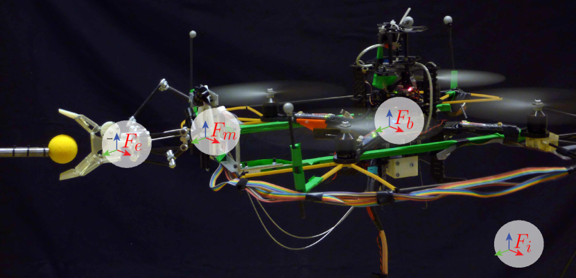
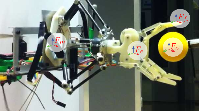
The complete system is composed of three main parts, as shown in Figure 1. The first is the underactuated quadrotor UAV. The second part is the robotic manipulator, whose design is based on a delta parallel kinematic structure, as presented in [12]. It enables Cartesian movement of its end-effector in the workspace and it is attached to one side of the quadrotor UAV. Finally, the third part is the underactuated gripper, whose design is inspired by the work presented in [15]. The mechanical structure of the gripper consists of three fingers, with two phalanges each, and is actuated by one single motor. The construction of the gripper is such that form closure is guaranteed. The robotic manipulator and the gripper are shown in Figure 2.
II-B Notation
Before proceeding with the description of the system dynamics, all used symbols are briefly explained for clarity. With reference to Figures 1 and 2, the kinematic notation is:
-
•
, , , , , and represent the inertial frame, the body frame of the UAV fixed at its centre of gravity (c.g.), the base frame of the robotic manipulator, the base frame of the palm of the gripper (coincident to the base frame of the end effector of the manipulator), the frame at the contact points on the fingers of the gripper, and the object frame;
-
•
and the position and rotation matrix of a generic frame with respect to a generic frame .
The dynamic notation is:
-
•
the gravitational acceleration;
-
•
, are the UAV’s mass and inertia matrix;
-
•
and are the mass of the robotic manipulator (including the palm on the gripper) and of the object, respectively;
-
•
the total thrust on the vehicle generated by its propellers, the force the robotic manipulator and the UAV exert on each other at the robotic manipulator base;
-
•
the moment vector due to the gyration effects of the propellers, the control torque of the vehicle, the reaction torque the robotic manipulator and the UAV exchange at the robotic manipulator base;
-
•
the forces and moments due to the absolute motion of the robotic manipulator in ;
-
•
the forces and moments due to the absolute motion of the robotic manipulator in ;
-
•
the forces and moments due to the absolute motion of the object in ;
-
•
the force and moment the gripper and the robotic manipulator’s end-effector exert on each other;
-
•
the force and the moment that make up the total wrench, , the object exerts on the gripper’s fingers and palm in the object frame, .
The dynamic model of the complete system is seen as a cascade of subsystems, interconnected at certain points by means of localized interaction forces and moments. It is assumed that the system interacts with the environment by means of the manipulator’s end effector and the phalanges only, i.e. only in and . Furthermore, the connections between the UAV and the robotic manipulator’s base in as well as between the robotic manipulator’s end-effector and the gripper palm in are assumed to be rigid. The UAV is unconstrained in and can thus move freely with respect to the inertial frame, .
II-C The Quadrotor Dynamics
The quadrotor is an underactuated system, since it has only four control inputs , i.e. its propellers, and six degrees of freedom (DoFs). Due to the mechanical design of the quadrotor, a net torque can be applied in any direction by varying the relative thrust of the propellers. The mapping between the generated force of each propeller and the total thrust and torque exerted on the UAV’s c.g. is given by
where is the distance between the UAV’s c.g. and the centre of the propeller, and is the ratio between the propeller reaction torque and generated thrust. Using this, the full dynamics of the UAV can be described by
| (1) |
where and are the rotational velocity and acceleration of the UAV’s c.g. with respect to expressed in , respectively; is the linear acceleration of the UAV’s c.g. expressed in .
II-D The Robotic Manipulator Dynamics
The dynamics of the robotic manipulator can be compactly described by considering the internal and external contributions. The former includes inertial, Coriolis, centrifugal and gravitational forces/moments as well as the dynamic influence of the actuators. The latter upholds forces and moments exchanged at the end effector with the gripper and due to interaction with the environment. From the equilibrium of forces and moments, the dynamics of the robotic manipulator in is given by
| (2) |
II-E The Gripper Dynamics
Similarly to the robotic manipulator, the dynamics of the gripper can be compactly described by considering the internal and external contributions. Therefore, the dynamics of the gripper is described by
| (3) |
II-F The Environment
The system can be in three different states: free-flight (no object), dock (on the object) and aerial grasp (with object). Therefore, both and in Eq. 3 can have three different interpretations, depending on which state the system is in. These three states and their influence on the system are explained hereafter.
II-F1 Free-flight state (no object)
In this state, the UAV is in free flight and no object is grasped. This results in no external force and moment, i.e.,
II-F2 Dock state (on the object)
In this state, the UAV is docked on the object and, more precisely, it is docked by means of the gripper that is grasping the object attached to a vertical surface. The reaction forces and moments are partly due to the contact between the object and the palm of the gripper and partly due to the interaction between the object and the phalanges of the gripper. These forces and moments are described by
| (4) |
where is the grasp matrix and
is the net vector of the contact forces on the phalanges and the palm. Each element of consists of a normal component, modelled with the Hunt-Crossley model [16], and two tangential friction components.
II-F3 Aerial grasp state (with object)
When the object is detached from the vertical wall, it becomes part of the complete system. The dynamic contribution of the object is
III CONTROL
In this section we present the control architecture, which consists of a cascade of three impedance controllers. Each controller is designed separately for each one of the three subsystems, as described in Section II.
III-A The Quadrotor
Assuming a high attitude control authority like in [13], which compensates the momenta imposed on the system, the UAV’s system dynamics in Eq. 1 can be simplified as
| (5) |
where is the only controllable input. This is chosen to be
| (6) |
with as a new input. Substituting Eq. 6 into Eq. 5, it results
in which . In this way, the system resembles a mass driven by an external force and an input that has still to be designed.
Now let be the desired position for the aerial vehicle. By choosing to be equal to
the system is impedance controlled. The gains and can be chosen according to the desired system bandwidth and relative damping; is a feed-forward term that compensates for the gravitational contributions of the robotic manipulator, the gripper and the object, when detached from the wall.
III-B The Robotic Manipulator
In its essence the control of the robotic manipulator is similar to the control of the UAV. The only difference is the way the inputs map to the robotic manipulator’s end effector position, which is described by the Jacobian of the delta structure. Note that the high attitude control authority on the UAV compensates for the momenta that the robotic manipulator and the UAV exchange.
By making explicit in Eq. 2, the dynamics of the robotic manipulator can be written as
| (7) |
where contains the gravitational, Coriolis and centrifugal components of the robotic manipulator, is the end effector acceleration and in which, for simplicity, we assumed that the manipulator mass is concentrated on the end-effector. The controllable input part is chosen to be
| (8) |
with as a new input. By substituting Eq. 8 in Eq. 7, the following is obtained
| (9) |
in which .
Again the dynamics of this subsystem resembles a mass driven by an external force. Let a desired virtual point be represented by , if is defined as
| (10) |
the system is impedance controlled. The gains and can be chosen according to the desired system behavior; is a feed-forward term that compensates for the gravitational contributions of the gripper and the object, when detached from the wall.
III-C The Gripper
In order to have the overall system consisting of impedance controlled subsystems, we design the control for the gripper in a similar manner as the previous subsystems. Before that, it should be noted that the only interesting state from a control point of view is the dock state, since in both other states the gripper is either idle in its open state or idle in a closed state. Note that the high attitude control authority on the UAV compensates for the momenta that the gripper and the robotic manipulator exchange.
From Eq. 3 in the dock state, it results in
| (11) |
where contains the gravitational, Coriolis and centrifugal components of the gripper, are the inertial forces of the phalanges. Note that the mass of the palm is not considered here since it is included in the end-effector.
The controllable input part is chosen to be
| (12) |
where is a new input. By substituting Eq. 12 in Eq. 11, it follows that
with . The gripper is impedance controlled if the input is chosen as
where is the desired position of the gripper’s fingers, and are properly chosen gains, and is a feed-forward term that compensates for the gravitational contributions of the object, when detached from the wall.
Note that as the gripper is an underactuated system, there is only one actuator to actuate three fingers with two phalanges each. This implies that the pseudoinverse of the grasp matrix should be computed to calculate and .
III-D Stability Analysis
The three subsystems, as described in the previous subsections, have the same generalized closed loop system, i.e.,
| (13) |
where denotes the frame that corresponds to the subsystem. Therefore a single stability analysis will suffice. In fact the described system turns out to be output strictly passive [17] by choosing input , output and storage function , where is the kinetic energy and is the potential energy, which has a minimum at the desired position . As shown in [17][Lemma 6.7] the above property of output strict passivity can be linked to zero-input asymptotic stability via zero-state observability and can be shown to hold for the generalized dynamics of the subsystems in Eq. 13. This means that all the subsystems asymptotically reach the desired set-points, denoted in Eq. 13, provided their input forces are zero. Due to the cascaded nature of the subsystems and the fact that all of the subsystems are asymptotically stable, the overall system is also asymptotically stable [18].
IV RESULTS
In this section, we provide simulations and experimental tests that validate the proposed control strategy.
IV-A Simulations
To simulate the whole system, the model is implemented in the simulation package 20-sim (Controllab Products B.V., The Netherlands). By simulating the model, it can be shown that stable flight and stable interaction can be achieved.
IV-A1 Quadrotor path tracking
Figure 3 shows the simulation results for the quadrotor UAV while tracking a certain path. The three operating states are shown sequentially.

At the beginning, the UAV is in free-flight state (no object). Upon contact with the object at s, the system is in dock state (on the object). When the object is fully grasped and the UAV flies away from the wall at s, the object is detached from the wall and becomes a part of the complete system. The system is finally in its aerial grasp state.
The quadrotor is capable of tracking the path in all the states. Some tracking errors are present, due to impedance control, and some larger fluctuations can be seen when the system is in contact with the environment, even if stability is guaranteed. The tracking error converges to zero when the setpoint is constant for a sufficient amount of time. This is in accordance with the stability analysis in Section III-D.
IV-A2 Robotic manipulator path tracking
To asses the correct functioning of the robotic manipulator, the tracking capability with respect to the manipulator base frame, , is shown in Figure 4.
Note that object tracking is disabled for s as there is no need to track any object yet, and enabling object tracking would only result in unnecessary disturbances on the system. At s, the object tracking is disabled again as this is no longer useful when the object is detached from the wall.

The tracking capabilities of the robotic manipulator prove to be sufficient to retain a stable system. Note that larger fluctuations occur when the system is in contact with the environment, but the tracking and the overall stability are still guaranteed. The spikes at the time of impact are due to the displacement of the UAV on impact, as shown in the middle plot in Figure 3. The sudden change in , which is the height with respect to , can be caused by the contact friction and by the fact that the quadrotor is not yet stabilized.
IV-B Experimental setup
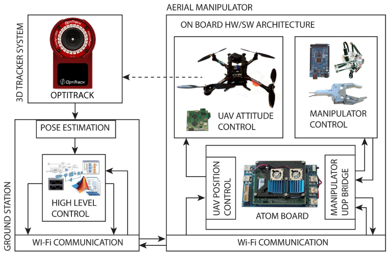
To verify the proposed control strategy, a test setup has been build together with a software architecture, as sketched in Figure 5. The different modules are:
-
•
Aerial vehicle: a Pelican quadrotor (Ascending Technologies, Germany), with payload capability of g.
-
•
Robotic manipulator: a DoFs Cartesian delta robotic manipulator [12]. The control of this system runs on an Arduino ATMega2560 and it receives setpoints by the ground station by means of a WiFi data link.
-
•
Gripper: a 3D printed gripper system consisting of three fingers with two phalanges each. The system is actuated by one motor attached to the aerial vehicle and connected via bowden cables to the gripper in order to minimize the UAV’s inertia. The motor itself is controlled by the microcontroller on the Arduino.
-
•
External positioning system: the positions of the subsystems in the inertial frame, , are estimated by an external optical tracking system OptiTrack Flex 13 (NaturalPoint, Inc., USA).
-
•
Ground station: the high-level controller of the system runs on Ubuntu Linux 10.10. It generates trajectories and estimates positions, based on the input of the OptiTrack. The communication between the different software modules is performed using the Robot Operating System ROS. Setpoints generated for both the robotic manipulator and the gripper are relayed to the integrated microcontroller via WiFi (802.11n standard).
IV-C Experiment validation
In the experiments, the robotic manipulator approaches the object in the inertial frame. To achieve that, the desired pose of the robotic manipulator is derived by using the measured UAV’s position and the desired point on the vertical wall. Once the UAV is in front of the object, the gripper grasps the object, detaches it from the wall and flies away.
Figure 6 shows that the UAV is capable of tracking the given setpoints in all three states. The UAV starts in free-flight and, at approximately s, the object is grasped. Few seconds later the object is removed from the vertical wall leaving the UAV again in free-flight mode.

During the experiment the robotic manipulator tracks its setpoint. This can clearly be seen in Figure 7 since the z- and x-position are almost in their outmost position (i.e. mm for z and mm for x). At s, the inertial position tracking is visible as the peaks in both the y- and z-setpoints. After grasping, the robotic manipulator keeps on tracking the given setpoint which causes it to move outward again, but with a grasped object. Good tracking performance and stability are also shown in the accompanying video.

V Conclusions
In this paper, we presented the design of a control architecture for a flying hand. The overall system consists of a quadrotor UAV, a robotic manipulator and a gripper, which is grasping an object fixed on a vertical wall. The control strategy is based on passivity-based techniques and has been shown to guarantee the asymptotic stability of the system in both simulations and in experimental tests.
References
- [1] L. Marconi, L. Basile, G. Caprari, R. Carloni, P. Chiacchio, C. Huerzeler, V. Lippiello, R. Naldi, J. Nikolic, B. Siciliano, S. Stramigioli, and E. Zwicker, “Aerial service robotics: the AIRobots perspective,” in Proceedings of the International Conference on Applied Robotics for the Power Industry, 2012.
- [2] C. Huerzeler, R. Naldi, V. Lippiello, R. Carloni, J. Nikolic, K. Alexis, L. Marconi, and R. Siegwart, “AIRobots: innovative aerial service robots for remote inspection by contact,” in Proceedings of the IEEE/RSJ International Conference on Intelligent Robots and Systems, 2013.
- [3] D. Mellinger, M. Shomin, N. Michael, and V. Kumar, “Cooperative grasping and transport using multiple quadrotors,” in Proceedings of the International Symposium on Distributed Autonomous Robotic Systems, 2010.
- [4] Q. Lindsey, D. Mellinger, and V. Kumar, “Construction of cubic structures with quadrotor teams,” in Proceedings of the Robotics: Science and Systems Conference, 2011.
- [5] A. Desbiens and M. Cutkosky, “Landing and perching on vertical surfaces with microspines for small unmanned air vehicle,” Journal of Intelligent & Robotic Systems, vol. 1, no. 4, pp. 313–327, 2009.
- [6] A. Frank, J. McGrew, M. Valenti, D. Levine, and J. How, “Hover, transition, and level flight control design for a single-propeller indoor airplane,” in Proceedings of the AIAA Guidance, Navigation and Control Conference, 2007.
- [7] A. Albers, S. Trautmann, T. Howard, T. Nguyen, M. Frietsch, and C.Sauter, “Semi-autonomous flying robot for physical interaction with environment,” in Proceedings of the IEEE Conference on Robotics Automation and Mechatronics, 2010.
- [8] L. Marconi, R. Naldi, and L. Gentili, “Modeling and control of a flying robot interacting with the environment,” Automatica, vol. 47, no. 12, pp. 2571 – 2583, 2011.
- [9] P. Pounds, D. Bersak, and A. Dollar, “Grasping from the air: hovering capture and load stability,” in Proceedings of the IEEE International Conference on Robotics and Automation, 2011.
- [10] P. Pounds and A. Dollar, “UAV rotorcraft in compliant contact: Stability analysis and simulation,” in Proceedings of the IEEE/RSJ International Conference on Intelligent Robots and Systems, 2011.
- [11] C. Korpela, T. Danko, and P. Oh, “MM-UAV: Mobile manipulating unmanned aerial vehicle,” Journal of Intelligent & Robotic Systems, vol. 65, no. 1–4, pp. 93–101, 2012.
- [12] A. Keemink, M. Fumagalli, S. Stramigioli, and R. Carloni, “Mechanical design of a manipulation system for unmanned aerial vehicles,” in Proceedings of the IEEE International Conference on Robotics and Automation, 2012.
- [13] M. Fumagalli, R. Naldi, A. Macchelli, R. Carloni, S. Stramigioli, and L. Marconi, “Modeling and control of a flying robot for contact inspection,” in Proceedings of the IEEE/RSJ International Conference on Intelligent Robots and Systems, 2012.
- [14] J. Scholten, M. Fumagalli, S. Stramigioli, and R. Carloni, “Interaction control of an uav endowed with a manipulator,” in Proceedings of the IEEE International Conference on Robotics and Automation, 2013.
- [15] G. A. Kragten, “Underactuated hands - fundamentals, performance analysis and design,” Ph.D. dissertation, TU Delft, The Netherlands, 2011.
- [16] N. Diolaiti, C. Melchiorri, and S. Stramigioli, “Contact impedance estimation for robotic systems,” IEEE Transactions on Robotics, vol. 21, no. 5, pp. 925–935, 2005.
- [17] H. K. Khalil, Nonlinear Systems. Prentice Hall, 1996.
- [18] N. Hogan, “Impedance control: An approach to manipulation,” Journal of Dynamic Systems, Measurement, and Control, vol. 107, no. 1, pp. 1 – 24, 1985.