Can hail and rain nucleate cloud droplets?
Abstract
We present results from moist convection in a mixture of pressurized sulfur hexafluoride (liquid and vapor), and helium (gas) to model the wet and dry components of the earth’s atmosphere. To allow for homogeneous nucleation, we operate the experiment close to critical conditions. We report on the nucleation of microdroplets in the wake of large cold liquid drops falling through the supersaturated atmosphere and show that the homogeneous nucleation is caused by isobaric cooling of the saturated sulfur hexaflouride vapor. Our results carry over to atmospheric clouds: falling hail and cold rain drops may enhance the heterogeneous nucleation of microdroplets in their wake under supersaturated atmospheric conditions. We also observed that under appropriate conditions settling microdroplets form a rather stable horizontal cloud layer, which separates regions of super- and sub critical saturation.
A key process in cloud dynamics is nucleation, i.e., the formation of condensation nuclei under supersaturated conditions that eventually grow to form micrometer size cloud droplets Pruppacher and Klett (2010). It is well known that the cloud dynamics and the formation of precipitation size droplets are strongly influenced by the concentration and the properties of the aerosol particles Pruppacher and Klett (2010). Inspired by laboratory experiments Schaefer (1946); Vonnegut (1947), several field experiments were conducted to enhance precipitation in clouds. In two seminal studies Langmuir (1948); Kraus and Squires (1947) dry ice was dropped on top of developing cumulus clouds, which in most cases triggered explosive cloud growth with significant rainfall in its neighborhood. Since then several investigations have been carried out to understand the dynamics associated with nucleation in clouds with and without seeding Pruppacher and Klett (2010); Bruintjes (1999); Mason (1982); Kopp et al. (1983).
In this letter, we report experimental findings on nucleation in a multiphase convection system consisting of sulfur hexafluoride (SF6) and helium (He). This system aims to mimic atmospheric conditions with SF6 existing in both liquid and vapor phases, thus acting as the moist component. Helium is added to mimic the dry component in the earth’s atmosphere. The advantage of using SF6 is that a relatively small supersaturation is required to trigger homogeneous nucleation Ye et al. (2000).
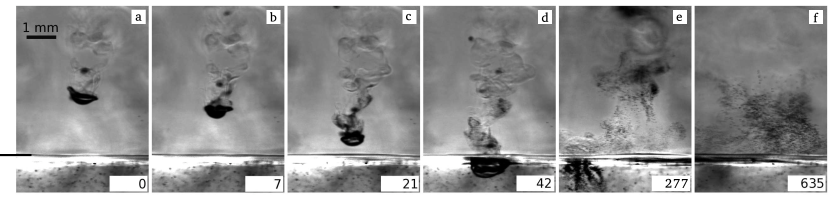
The nucleation of SF6 microdroplets in the wake of cold SF6 drops falling from the top plate (Fig. 1) is our main finding. We argue that the induced isobaric cooling in the wake increases locally the saturation ratio, and therefore triggers homogeneous nucleation. We show that a similar mechanism carries over to atmospheric clouds, where falling ice particles (hail) and/or large, cold rain drops can enhance the heterogeneous nucleation rate of droplets. Furthermore, in the experiment, under appropriate conditions, we observe the nucleated SF6 droplets forming a rather stable horizontal cloud layer, separating regions of sub- and super critical saturation, just as in an atmospheric cloud layer.
The experiments were performed in a high-pressure convection apparatus that has previously been used to study pattern formation close to the onset of convection de Bruyn et al. (1996); Plapp et al. (1998); Weiss et al. (2014). The main part of the apparatus is the convection cell (Fig. 2) that consists of two horizontal plates, H=(22.6) mm apart from each other. The side walls of the cell were made of acrylic with a square cross section of side length L=(61.65) mm. The top plate, a mm thick monocrystalline sapphire providing optical access, was kept horizontal and was cooled by circulating water on its top surface. The bottom plate was a mm thick monocrystalline silicon disc that was heated with an ohmic film heater at its bottom side. The top and bottom plate temperatures were regulated to 10 mK of the set temperature. In order to provide visual access from the side two sets of mirrors were embedded into the acrylic side walls at 45 degrees. One set of mirrors provides optical access to the top half and the other set to the bottom half of the cell (Fig. 2). Image acquisition was done at 140 fps at a resolution of 2048 x 2048 cam .
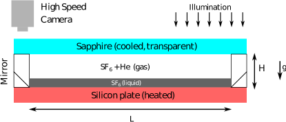
The bottom plate was heated to a temperature Tb, while the top plate was maintained at Tt Tb. The conditions were such that a layer of liquid SF6 formed at the bottom of the cell. At the liquid-gas interface, SF6 evaporated, rose and condensed underneath the top plate creating a thin liquid film, which continuously underwent a Rayleigh-Taylor like instability. As a consequence, drops of SF6 dripped and fell through the gas layer into the liquid SF6 pool at the bottom.
Figure 1 shows a deformed drop with a lateral diameter about 1 mm, accompanied by a smaller drop falling through the gaseous SF6-He atmosphere. Since these drops originated from the liquid layer at the top plate, their temperature is close to Tt. Local inhomogeneities in the gas temperature, hence in the refractive index, are visible in the wake of the cold drop by shadowgraphy (Fig. 1(a-d)). In the near wake of the deformed drop, the shed vortices mix the cold gas from the boundary layer with the warmer ambient gas as shown in Fig. 1(a-d), thus locally altering the saturation ratio and temperature. Particularly in Fig. 1c, the enhanced contrast in the near wake is due to the nucleation of microdroplets which become visible in Fig. 1d. Please note that the large drop enters the liquid pool without a visible splash. These microdroplets continue to grow in size by condensation of SF6 vapor from their supersaturated neighborhood till they fall into the liquid pool (Fig. 1 (e,f) and movie in sup ). Note that for fixed experimental conditions the number of nucleated microdroplets vary strongly for different falling drops (see movie in sup ). This points to a nonuniform distribution of SF6 vapor due to the turbulent convection in the gaseous layer.
In the experiment shown in Fig. 1, the temperature at the top and bottom plates were TC and TC, and the pressure was ) bar. Based on Dalton’s law, we estimate the mole fraction of He inside the gaseous layer to be %. We found that the nucleation of microdroplets in the wake of a falling drop was observed when Tb was sufficiently close to the critical temperature of SF6 (45.57 ∘C) at a fixed Tb - Tt. As we show below, this can be attributed to the lowering of the critical supersaturation required for nucleation as the critical temperature is approached.
Classical nucleation theory Feder et al. (1966); Zeldovich (1943) provides an estimate for the rate of formation of liquid phase critical droplets (”embryos”), , as a function of the saturation ratio, . By convention Pruppacher and Klett (2010), the detectable rate of nucleation is taken to be cm-3s-1. This leads to a definition of a critical saturation ratio . The corresponding critical size that needs to be exceeded for a sustained droplet growth is calculated using the Kelvin’s equation sup .
For the mean temperature C, using SF6 parameters Guder and Wagner (2009); Lemmon et al. (2013); det , we find , nm and the time to establish the steady-state nucleation rate s (see sup ). Using Maxwell’s model (diffusion limited growth), we estimate the time for growth by condensation from an initial radius of to m to ms sup . This time agrees remarkably well with the time difference between Fig. 1(a) and Fig. 1(d), i.e., the time interval between the cooling of the ambient gas at a certain location and the first appearance of microdroplets in its neighborhood.
In the experiment, the SF6 vapor close to a falling cold drop is cooled from an initial temperature to due to diffusive and convective heat transport from the drop’s surface. As a consequence, the saturation ratio becomes , where represents the temperature difference between the ambient gas and the wake. For C of saturated SF6 vapor, i.e. , a K is sufficient to reach , in comparison to a K at C. Note that the cooling in the wake to K is attainable, given that the temperature of the cold falling drop was initially K below the mean temperature in the cell. To show this, we estimate the cooling, i.e., the temperature difference between the ambient gas and a drop of diameter , falling at its terminal velocity , in a gas layer of temperature decreasing linearly with height. We find:
| (1) |
where , , Nu is the Nusselt number (ratio between convective and conductive heat transfer), is the thermal conductivity of the ambient gas, , are the density, and the specific heat of the liquid respectively (see sup for additional details).
In Fig. 1, the diameter of the cold SF6 drops detaching from the top plate mm. From the recorded images, we found that the terminal velocity of the drop Ut 7 cm/s was reached after about a mm fall from the top plate. Drops reach the liquid layer above the bottom plate in about s. Using the material parameters of SF6 at C det and an empirical relation between the drop Reynolds number (Re), and Nu Whitaker (1972), we find and , and thus from Eq. (1), s. Let us assume that when the drop attains its terminal velocity (), it has the same temperature as its ambient, i.e., . To account for convective mixing in the gas layer we choose K/cm, which is four times smaller than the applied temperature gradient of K/cm across the gas layer. Equation (1) predicts that K and K at ms and ms, respectively, which is well before the drop enters the liquid pool.
The cooling in the wake of the drop is determined by the heat transfer rate from the ambient gas to the cold drop and as such is a function of Re of the falling drop and the streamwise distance from the drop’s surface. Simulations at de Stadler et al. (2014) of the instantaneous temperature distribution in the near wake show that the separated shear layers retain up to % of till about droplet diameters downstream. The settling cold drop, with K, therefore induces isobaric cooling of the ambient wake by K at ms which is sufficient to trigger homogeneous nucleation at C. The cooling in the near wake is enhanced with further fall of the drop.
Please note that this is a simple estimate. In fact, the required to trigger homogeneous nucleation also depends on the distribution of SF6 vapor in the boundary layer and the wake. Moreover, additional complexities arise due to the mixing of parcels of different temperature and vapor content. We here assume that the SF6 vapor content is constant and saturated at . As a consequence, the level of supersaturation estimated by isobaric cooling with constant SF6 vapor content gives an upper bound.
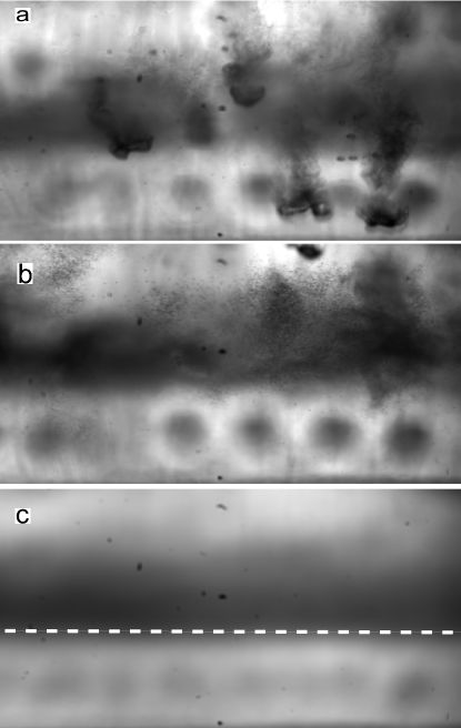
If the bottom plate is covered by a liquid layer, the SF6 vapor in the gas is on average saturated or slightly supersaturated due to the continuous supply of vapor from the liquid pool below. As a consequence, any sufficiently large microdroplet would continue to grow till it reaches the liquid layer. The saturation ratio , of SF6 vapor inside the cell can be lowered by eliminating the liquid layer above the bottom plate while keeping all the other parameters fixed, thus cutting off the vapor supply. In such cases, in the upper, colder part of the cell, while in the warmer lower part. Figure 3 displays the observations in the lower part of the cell in the absence of a liquid layer on the bottom. The microdroplets were nucleated in the wake of drops falling from the top plate, similar to that in Fig. 1, except that sustained nucleation in the wake was observed only above a certain height (see Fig. 3a, b and movie in sup ). This height marks the horizontal interface where . In the region above this interface, the nucleated microdroplets grow in size and below the interface they evaporate (see movie in sup ). Figure 3b shows a layer of microdroplets suspended in the gas layer. The dark band in Fig. 3c represents the time averaged cloud layer and it suggests that the layer has a well defined base, similar to the clouds in the earth’s atmosphere. The mean position (averaged over 1550 frames, seconds) of this base is marked in Fig. 3c. Below this interface no sustained nucleation was observed.
Let us now compare the conditions in the earth’s atmosphere with those in the experiment and check under which conditions the present observations can be carried over. Due to the much larger surface tension of water in comparison to SF6, the saturation ratio required to achieve for water vapor is much higher. For example, for homogeneous nucleation of liquid water in the moist air for the temperature range C C the critical saturation ratio varies between and . However, the supersaturation that develops in natural clouds rarely exceeds a few percent Pruppacher and Klett (2010). Consequently, water droplets do not form by homogeneous nucleation but rather by heterogeneous nucleation on atmospheric aerosol particles Pruppacher and Klett (2010). The number of particles capable of growing, denoted as cloud condensation nuclei (CCN) grows with supersaturation, , typically with a power law dependence on Pruppacher and Klett (2010).
Consider moist cloudy air at temperature and that contains a certain amount of the CCN. When a large cold water drop (or hail particle), falls through a warmer ambient air, it will cause isobaric cooling of the air in its wake, similar to the drops in our experiment. This results in locally enhanced supersaturation that can create more CCN, and an increase in the number of microdroplets. For example, to attain a supersaturation % by isobaric cooling starting from the saturated vapor, a temperature drop of K K (varies almost linearly) for the temperature range C C is needed.
In a cloud, the ambient temperature surrounding a falling rain drop increases as the drop approaches the cloud base. We assume that the temperature variation within a cloud is linear with a typical moist adiabatic lapse rate K/m Bohren and Albrecht (1998). Then for a raindrop at its terminal velocity , the steady state temperature difference between the ambient air and the drop, , is calculated using Eq. (1). For a drop of diameter mm ( mm), one finds is about K ( K) (see sup ). The for the mm drop is too small to cause significant supersaturation in its wake. However, for a mm drop, the resulting cooling in the wake, K is sufficient to attain about % supersaturation and thus leads to enhanced nucleation in its wake.
In the case of a falling ice particle, as the ambient temperature increases above C, ice particles begin to melt, a process that extracts heat from its surrounding, thus resulting in a supersaturation in the wake that is higher than that of a rain drop of the same diameter. It is known that the temperature inside a particle composed of a mixture of liquid water and ice is nearly homogeneous due to the shear enhanced mixing inside the particle Rasmussen et al. (1984). As a consequence the temperature of the ice particle would not increase until it is completely melted. The heat transfer rate is also known to depend on the shape of the ice particle Rasmussen et al. (1984). Let us assume a spherical particle of uniform density. To account for liquid condensation on the surface, we further assume a 25% larger heat transfer rate between the particle and its surrounding than for the liquid drop Mason (1956). Based on these considerations an ice particle of mm diameter () would travel m and a particle of diameter mm () would travel m before it is completely melted. The corresponding maximum for these particles are about K and K, respectively (see sup for details). As a consequence, the local supersaturation would be around % in the near wake of the particle taking into account . This enhanced supersaturation would activate more nuclei and hence increase the concentration of microdroplets in the warmer part of the cloud. Note, that for an aerosol particle with radius m, the time required to activate the CCN is smaller than the Kolmogorov time scale in the clouds Pruppacher and Klett (2010).
The estimates here are based on idealized conditions. In a (convective) cloud, the dynamics is more complicated due to the presence of updrafts, variable lapse rates due to non-uniform latent heat release from condensation/glaciation, and inhomogeneous mixing due to entrainment of ambient dry air into the cloud Lehmann et al. (2009). Nevertheless, the results from our model system and the analysis presented in this letter suggest that in clouds, the cooling induced by a falling hail particle can indeed lead to the nucleation of droplets. This effect may play an important role, as the droplets produced by this mechanism may either collide and aggregate with other settling hail or rain drops, or be entrained into an updraft, to further reinforce the production of hail or large rain drops. Moreover, the additional latent heat released due to the nucleation of new droplets can feed energy to the existing updraft.
The results presented in this letter revealed an unexpected mechanism of nucleation and growth of microdroplets in nonequlibirum conditions, such as those in the atmosphere. Our estimates predict that the enhanced nucleation of small droplets by a cold falling drop or ice particle, former clearly observed in the experiments, should also play a role in clouds. It is worth noting that the ideas developed here could be potentially extended to the nucleation of small ice crystals in the wake of large hail particles or graupels. Testing the ideas presented here will require additional experiments under atmospheric conditions.
References
- Pruppacher and Klett (2010) H. Pruppacher and J. Klett, Microphysics of Clouds and Precipitation (Springer, 2010).
- Schaefer (1946) V. J. Schaefer, Science 104, 457 (1946).
- Vonnegut (1947) B. Vonnegut, J. Appl. Phys. 18, 593 (1947).
- Langmuir (1948) I. Langmuir, J. Meteorol. 5, 175 (1948).
- Kraus and Squires (1947) E. B. Kraus and P. Squires, Nature 159, 489 (1947).
- Bruintjes (1999) R. T. Bruintjes, Bull. Amer. Meteor. Soc. 80, 805 (1999).
- Mason (1982) B. Mason, Contemp. Phys. 23, 311 (1982).
- Kopp et al. (1983) F. J. Kopp, H. D. Orville, R. D. Farley, and J. H. Hirsch, J. Appl. Meteorol. 22, 1542 (1983).
- Ye et al. (2000) P. Ye, A. Bertelsmann, R. H. Heist, B. N. Hale, and M. Kulmala, in AIP Conference Proceedings, Vol. 534 (AIP, 2000) pp. 19–22.
- de Bruyn et al. (1996) J. R. de Bruyn, E. Bodenschatz, S. W. Morris, S. Trainoff, Y. Hu, D. S. Cannell, and G. Ahlers, Rev. Sci. Instrum. 67, 2043 (1996).
- Plapp et al. (1998) B. B. Plapp, D. A. Egolf, E. Bodenschatz, and W. Pesch, Phys. Rev. Lett. 81, 5334 (1998).
- Weiss et al. (2014) S. Weiss, G. Seiden, and E. Bodenschatz, J. Fluid Mech. 756, 293 (2014).
- (13) Phantom 65 Gold Camera, Vision Research.
- (14) See Supplemental Material for additional details and movies, which includes Ref Clift and Gauvin (1971).
- Clift and Gauvin (1971) R. Clift and W. Gauvin, The Canadian Journal of Chemical Engineering 49, 439 (1971).
- Feder et al. (1966) J. Feder, K. C. Russell, J. Lothe, and G. M. Pound, Adv. Phys. 15, 111 (1966).
- Zeldovich (1943) J. B. Zeldovich, Acta Physicochimica URSS 18, 1 (1943).
- Guder and Wagner (2009) C. Guder and W. Wagner, J. Phys. Chem. Ref. Data 38, 33 (2009).
- Lemmon et al. (2013) E. W. Lemmon, M. L. Huber, and M. O. McLinden, NIST Standard Reference Database 23: Reference Fluid Thermodynamic and Transport Properties - REFPROP, Version 9.1, National Institute of Standards and Technology, Standard Reference Data Program, Gaithersburg (2013).
- (20) Material parameters of SF6 at C: bar, kg/m3, kg/m3, g/mol, mN/m.
- Whitaker (1972) S. Whitaker, AIChE Journal 18, 361 (1972).
- de Stadler et al. (2014) M. B. de Stadler, N. R. Rapaka, and S. Sarkar, Int. J. Heat Fluid Flow 49, 2 (2014).
- Bohren and Albrecht (1998) C. F. Bohren and B. A. Albrecht, Atmospheric Thermodynamics (Oxford University Press, New York, 1998).
- Rasmussen et al. (1984) R. Rasmussen, V. Levizzani, and H. Pruppacher, J. Atmos. Sci 41, 381 (1984).
- Mason (1956) B. J. Mason, Q. J. R. Meteorol. Soc. 82, 209 (1956).
- Lehmann et al. (2009) K. Lehmann, H. Siebert, and R. A. Shaw, J. Atmos. Sci 66, 3641 (2009).
Appendix A Homogeneous nucleation
Let us consider the conditions for homogeneous nucleation and growth of microdroplets in SF6 vapor. The saturation ratio is defined as the ratio of the vapor pressure and the saturation (equilibrium) vapor pressure at a given temperature, . According to classical nucleation theory [16, 17],the rate of formation of liquid phase critical droplets (“embryos”) for is given by
| (2) |
where is the density of the liquid phase, – its molecular weight, is the surface tension at the liquid-vapor interface, and are Avogadro’s and Boltzmann’s constants, respectively. By convention [1], the threshold defining a significant (detectable) rate of homogeneous nucleation is taken to be cm-3 s-1, which in turn leads to the definition of a critical value of the saturation, . In homogeneous nucleation, the critical size of the liquid droplet embryo, , required for a sustained droplet growth can be calculated using the Kelvin’s equation
| (3) |
The time lag to attain steady-state values for the nucleation-rate (see, e.g., [1, 16]) can be estimated as
| (4) |
where is the flux of vapor molecules to the droplet embryo surface at the vapor pressure and the temperature . Embryos with will grow initially by condensation of the molecules from the vapor onto their surface. According to Maxwell’s model (diffusion limited growth), the radius of the droplet changes with time as
| (5) |
where is the molecular diffusion coefficient and is the vapor density away from the droplet.
Appendix B Heat transfer from a raindrop
Let us consider the temperature in a gas layer decreases linearly with increasing height.
| (6) |
The falling droplet will encounter a warming environment and thus will heat up. The heat transfer rate into the droplet depends on its mass () and its effective heat conductivity . Here, Nu is the Nusselt number, the thermal conductivity of the ambient gas, the droplet diameter and its density. We can then write:
| (7) |
where, is the droplet temperature and specific heat of the liquid. We assume that the temperature inside the droplet is homogeneous due to shear enhanced mixing. The Nusselt number which expresses the ratio of convective and conductive heat transfer can be estimated for a falling sphere as [21]
| (8) |
where is the Reynolds number, is the Prandtl number, and , , are the density, the dynamic viscosity, and the specific heat of the ambient gas, respectively, is the terminal velocity of the drop. The drag coefficient required to calculate the terminal velocity iteratively from the equations of motion was obtained from [15]
Using Eq. (6) and rearranging the terms in Eq. (7), we get:
| (9) |
After the droplet has reached its terminal velocity , its vertical position is given by
| (10) |
We thus get
| (11) |
Using Eqs. (6), (9) we can write an evolution equation for the temperature difference between the droplet and local ambient temperature as
| (12) |
resulting in
| (13) |
where .
For the temperature profile in atmospheric clouds being the lapse rate, C/m. The material parameters for water and water vapor evaluated at 10C are the following: = 103 kg/m3, =4188 kg/m3, = 0.02 W/(m k).
Appendix C Melting of an ice particle in a warm cloud
Within earth’s atmospheric conditions an ice particle would start to melt as the temperature increases above 0C. The melt water collects around the ice particle. The surface temperature for this ice-water system will not increase until all the ice has melted [24]. Let us assume that the ice particle has attained its terminal velocity before entering the warm parts of a cloud, then we can state that the amount of energy required to melt the ice particle should balance the net heat transferred into this system from the ambient.
| (14) |
where, represents the specific enthalpy of fusion of ice, is the density of the ice. is 0C. Using equation 6 and integrating equation 14 with respect to time we get
| (15) |
= 916 kg m-3, lice = 335 KJ kg-1