Regrasp Planning using 10,000s of Grasps
Abstract
This paper develops intelligent algorithms for robots to reorient objects. Given the initial and goal poses of an object, the proposed algorithms plan a sequence of robot poses and grasp configurations that reorient the object from its initial pose to the goal. While the topic has been studied extensively in previous work, this paper makes important improvements in grasp planning by using over-segmented meshes, in data storage by using relational database, and in regrasp planning by mixing real-world roadmaps. The improvements enable robots to do robust regrasp planning using 10,000s of grasps and their relationships in interactive time. The proposed algorithms are validated using various objects and robots.
Index Terms:
Grasp Planning, Manipulation Planning, Reorient Objects, Preparatory PlanningI Introduction
This paper develops intelligent algorithms for robots to reorient objects. Given the mesh models of objects, their initial and goal poses, and the kinematic and dimensional parameters of robots, the algorithms developed in the paper could find a sequence of robot poses and grasp configurations that reorients the objects from their initial poses to the goals.
The algorithms developed include grasp planning algorithms, placement planning algorithms, and graph searching and motion planning algorithms. Developing these intelligent algorithms are important to industrial robots. In factories, objects are sent to robots in boxes. The objects are in various poses. A robot is required to recognize the objects, pick them up, and reorient them to specific poses for particular use. Examples include: (1) Packing items. Each item should be reoriented to the same orientation and packed into a box. (2) Assembly. Each part in the assembly should be reoriented to specific poses to fit others. (3) Using tools. A tool should be reoriented to have its tool center point facing targets. These tasks require a robot to be equipped with both high-precision vision systems and robust grasp and manipulation planning systems. This paper studies the grasp and manipulation planning systems. It develops robust algorithms to do regrasp by using 10,000s of auto-planned grasps.
The developed algorithms include: (1) A grasp planner which automatically plans available grasp configurations using the mesh models of objects. (2) A placement planner which automatically plans stable poses of an object on a planar surface (table top). (3) A regrasp planner which builds and searches regrasp graphs to generate a sequence of robot poses and grasp configurations that reorients objects from their initial poses to the goals.
While these algorithms have been studied for thirty years and also have been extensively discussed and re-developed in several of our previous work, this paper makes important improvements to make them robust. It leverages the computational ability of modern computers to deal with various robots, objects, and combinatorics. The main contributions are as follows. (1) We propose a grasp planning system which uses over-segmented mesh surfaces to sample contact points. The over-segmented surfaces provide more even segments and robuster measurement of contact regions. (2) We employ RDB (Relational DataBase) to manage the large amount of data generated by planning algorithms. RDB makes it easy to maintain the relationships among grasp configurations, placements, objects, and robots. It enables saving and retrieving gigabyte-level data to build regrasp graphs and select grasps and placements all over a table in front of a robot. (3) We build the regrasp graph like a roadmap in a robot’s workspace and search the graph to find a sequence of robot poses and grasp configurations that reorients the objects from their initial poses to the goals. The graph, together with contributions (1) and (2), makes it possible for different robots to reuse 10,000s of grasps and their relationships to reorient objects with various initial and goal poses in interactive time.
II Reorienting Objects using Regrasp Planning
The seminal work that studied reorienting objects using regrasp is [1]. The work motivated many researchers. [2][3][4][5] are some of the early publications that applied similar technique to various robots and grippers. These early work concentrated on the regrasp aspect. Their grasp and motion planning was limited by the computational capacities at that time. The number of grasps were small and the grasp planning was based on block models, primitive matching, or manually selected values.
More recent work involved better grasp and motion planning. For example, Xue et al. [6] used shape primitives [7] to plan grasps for a cup and implemented the regrasp and reorient planning of the cup using multi-finger hands. Saut et al. [8] used decomposition to plan grasps and implemented dual-arm regrasp of complicated models. King et al. [9] used regrasp planning to do preparatory reorient. They implemented primitive-based prehensile and non-prehensile grasp planning to prepare for optimal motion planning. Simeon et al. [10] presented a framework which integrated motion planning and transfer-transit regrasp. Hauser et al. [11] made a concrete description of multi-modal motion planning and presented several implementations. Yoshida et al. [12] applied regrasp and motion planning to a humanoid robot that transported a box. Cohen et al. [13] developed algorithms to sequentially handle an object using several manipulators and regrasp. Nguyen et al. [14] developed algorithms for a WALK-MAN robot to reorient an electric drill, using some carefully selected grasps to make the manipulation robust. Chang et al. [15] studied the preparatory grasps of human beings and used non-prehensile re-grasp (pushing) to reorient pans and pots. Lertkultanon et al. [16] presented an integrated regrasp and motion planning system to reorient furniture parts. Their grasps were based on box primitives. Krontiris et al. [17] developed algorithms to rearrange objects. Their focus was on the high level planning of manipulation sequence. Similarly, Jentzsch et al. [18] used regrasp to solve multi-modal pick-and-place problems. Lee et al. [19] also used non-prehensile grasp to plan sequential manipulation and reorient.
The essential algorithms in reorienting objects using regrasp include: (1) A grasp planner, (2) a placement planner, and (3) a regrasp planner. The grasp planner plans a redundant number of available grasps. The placement planner finds stable placements of the object in the environment. It also associates the grasps found by the grasp planner to the stable placements. Following the grasp planner and placement planner, the regrasp planner builds a regrasp graph by considering the shared grasps of the stable placements, connects the initial and goal poses to the graph by solving inverse kinematics and detecting collisions, and plans a sequence of robot poses and grasp configurations to reorient the object from its initial pose to the goal.
This paper makes improvements on grasp planning and data management. It proposes an improved grasp planning system using over-segmented facets, employs relational database to manage the large amount of data generated by planning algorithms, and builds and searches regrasp graphs like a roadmap in a robot’s workspace using the saved data and their relationships. These improvements make it possible for a robot to reuse 10,000s of grasps and relationships to reorient objects with various initial and goal poses in interactive time. To our best knowledge, it is the first work that reorients objects using such a large amount of data.
III Grasp Planning using Over-segmented Surfaces
Over-segmentation: We plan grasps by over-segmenting an object mesh into redundant number of facets. The pseudo code of the over-segmentation algorithm is shown in the upper part of Fig.2. Compared with the conventional algorithm shown in the lower part, the over-segmentation algorithm allows overlap between facets by repeatedly examining all triangle meshes. The conventional algorithm removes the expanded triangle meshes during segmentation, leading to uneven segmentation.
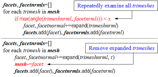
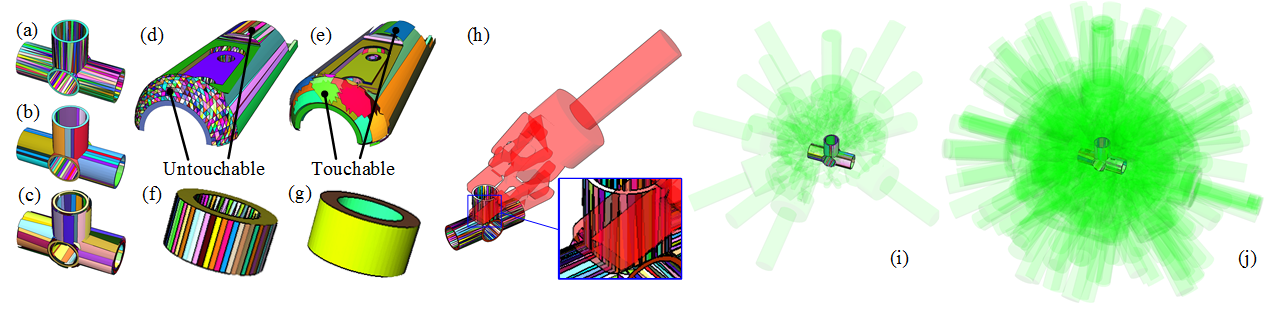
Fig.1 compares some results. Fig.1(a) and (b) are segmented using a conventional segmentation method which does not allow overlapped facets. (a) and (b) are the results of two different thresholds (parameter in Fig.2). Fig.1(c) is the result of the proposed over-segmentation method. The conventional segmentation method has several disadvantages: (1) It is difficult to judge if a facet is safe to touch or not. Take Fig.1(d) and (e) for example. In Fig.1(d), a curved mesh surface is segmented into several flat facets using the conventional segmentation method. Some of them are large, some others are small. Once triangle meshes are segmented to adjacent facets, the remaining ones will be small. Large facets are touchable, but small ones might be either touchable or untouchable. They are segmented independently from surrounding facets and their real touchability is difficult to judge. (2) It is difficult to tune the parameter which is used to decide coplanar triangle meshes. A large may result into non-planar facets. For example, the whole cylindrical surface in Fig.1(f) is mistaken as one facet. It is not planar. In contrast, a small results into many small facets in Fig.1(g), making it difficult to do surface sampling and compute parallel facet pairs. (3) The conventional segmentation method deteriorates the performance of grasp planning. If a facet is too small to support a finger pad, there will be no available grasps to grip at that facet, leading to fewer automatically planned grasps and low success rate during regrasp. For example, the facets in Fig.1(h) are segmented by the conventional segmentation method. They are too small to support a finger pad and no grips on the facet is available (the red hand in Fig.1(h) indicates an unavailable grasp). For this reason, the number of planned grasps using the conventional method is much smaller compared to the over-segmentation method (Fig.1(i) vs. Fig.1(j)). Considering these disadvantages, we propose the grasp planning using over-segmentation. Since the facets are over-segmented, they include the information of a local region. Planning grasps using the over-segmented facets are more robust and complete.
Mesh sampling: The next step is to sample some contact points on the facets. While probabilistically sampling points on each over-segmented facet is an intuitive method, it leads to redundancy. To avoid redundancy and repeatedly computing force-closures and performing collision detections, we pre-sample on the whole mesh surface and distribute the pre-sampled results to over-segmented facets. One sampled point could be distributed to multiple facets. In this way, we use one sample process to generate contact points for all over-segmented facets. Fig.3(a) and (b) show the results of the surface sampling and the sampled points distributed to one over-segmented facet.
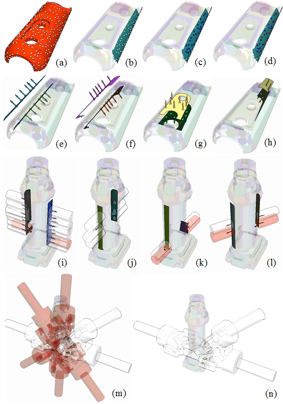
The sampled points are further refined using the following filters. (1) Distance filter. A sampled point must neither be too near to nor too far from the boundary of the facet. If a sampled point was too near to the boundary, the finger pad touching that point might be on the edges of the object, leading to unstable grasp configurations. On the other hand, if a sampled point was too far from the boundary, the palm of the hand might collide with the object. The distance filter removes these unstable and collided grasp configurations. A result of the distance filter is shown in Fig.3(c). (2) Near-neighbour filter. Two sampled points should not be too near to each other. Near sampled points increase the density of auto-planned grasp configurations, which is unnecessary and leads to high computational cost. We merge the sampled points in a region by representing them using a single point. The process is done using the fixed-radius nearest neighbour algorithm. The neighbours that fall inside the radius of a chosen sampled point will be removed. The result of the near-neighbour filter is shown in Fig.3(d).
Parallel facets: For a parallel gripper, the contact points of the two fingers pads must be on two parallel facets. Therefore we compute the force-closure grasps by finding all parallel facets where the sampled points on one facet can be projected to the inner region of the other facet along its inverse normal direction. Some results of the parallel facets are shown in Fig.3(e)-(h). The contact points, their projections, and the normals of the contact points and projections are illustrated using colored arrows.
One sampled point together with its projection on one of its parallel facet is called a pair of contact points. For each pair of contact points, we pose the two finger pads on them and sample the rotation of the hand around the axis passing through the contact pair. An example of the sampled rotations is shown in Fig.3(m) (ignore the color for this subsection, the rotated hands are gripping at a pair of contact points shown in Fig.3(k)).
Resistance to gravity torques: The resistance of a grasp to gravity torques is measured using the distance between the contact pair and the (center of mass) of the object. Since the object will be reoriented during manipulation, the maximum gravity torque would be where is the mass of the object, is the gravity constant, is the center of mass, is the center of the contact pair. If is larger than a threshold, the contact pair is judged to be unstable during reorient. The candidate grasp configurations at the contact pair will be removed.
Collision detection: Two levels of collision detection are used to remove collided grasps. The first level uses the swept volumes of the finger pads during closing the gripper to detect the collisions between finger pads and the object. The swept volumes are modeled as two cylinders since cylinder models are invariant to rotation around the axis passing through the contact pair and only one collision detection is needed. Some examples of the collision detections in the first level are shown in Fig.3(i)-(l). The second level uses the model of the robotic hand to remove the collisions between the whole hand and the object. The collision detection is performed at each sampled rotation around the axis passing through the contact pair. An example is shown in Fig.3(m) and (n) where the red hands indicate the collided grasp configurations. The white hands indicate the collision-free grasp configurations. The first level of collision detection is fast and reduces the necessity to check the collision between hands and objects at some contact pairs in the second level. They together expedite the collision detection process.
A fast grasp planner that plans robust grasp configurations to grasp objects of various shapes could be implemented using the aforementioned algorithms.
IV Using RDB to Manage the Planned Results
The auto-planned grasps, together with the stable placements and other pre-computed results are saved in a relational database for reuse and analysis. RDB (Relational DataBase), rather than file systems, is used to help process the large amount of data and their relationships.
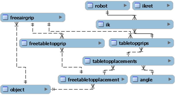
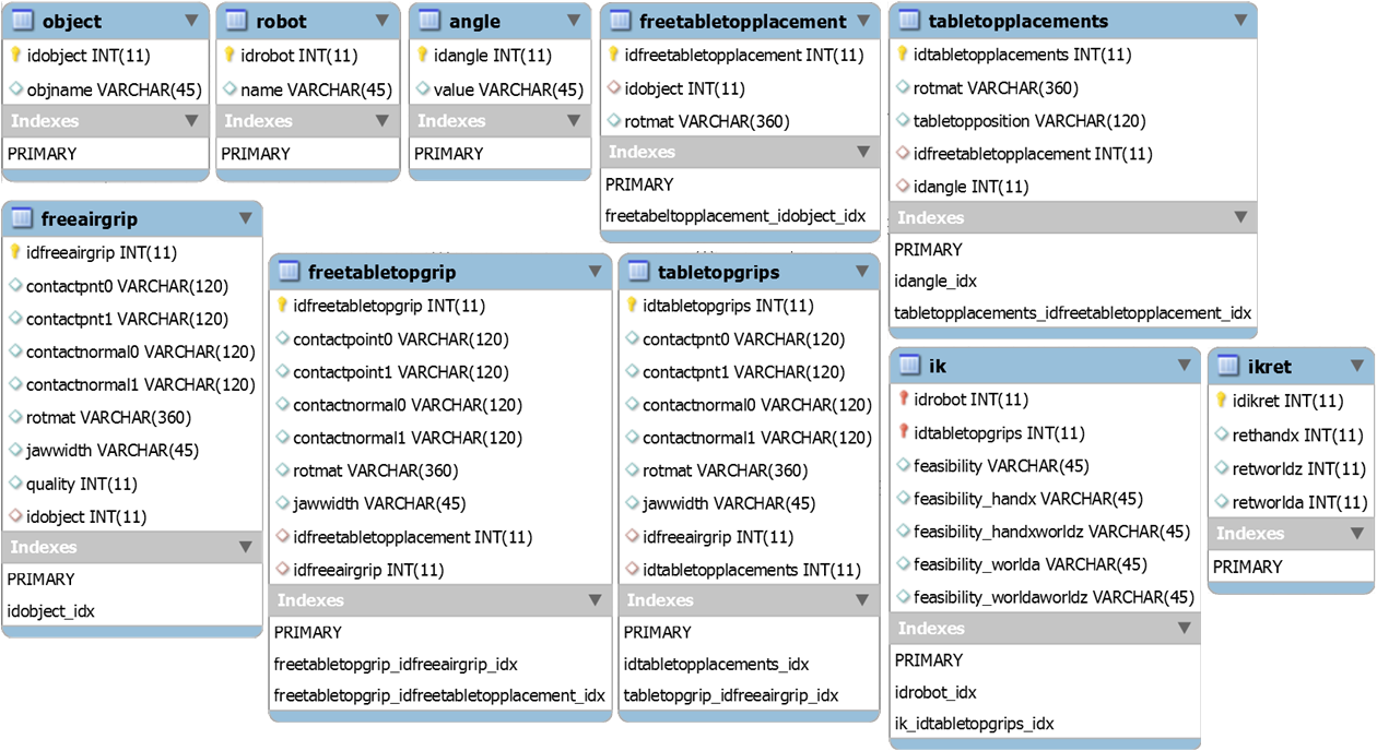
The ERG (Entity Relation Graph) of the database is shown in Fig.4. The database is composed of ten tables named object, robot, freeairgrip, freetabletopplacement, freetabletopgrip, angle, tabletopplacements, tabletopgrips, ikret, and ik, respectively.
The contents of the tables are shown in Fig.5. The object and robot tables save the names of the objects and robots. Each row of them has a primary key named idxxx(idobject or idrobot) and a second column storing the name. The freeairgrip table saves the grasp configurations in the local coordinate systems of objects, without considering surrounding obstacles. The freeairgrip table has a foreign key pointing to the id of object. It has a 1:n relationship with object (Fig.4). The freetabletopplacement table saves the placements of objects on a table. It is named free since the horizontal coordinates are always at (0,0), and the rotation around vertical axis is always 0 (they are ready to be displaced and rotated freely). The pose of the placements are saved in freetabletopplacement.rotmat. The freetabletopplacement table has a 1:n relationship with the object table and has a foreign key pointing to the id of object. The freetabletopgrip table saves the available grasp configurations of freetabletopplacement. Its columns include the contact points (contactpoint0 and contactpoint1), the contact normals (contactnormal0 and contactnormal1), the pose of the hand (rotmat), and the opening width of the jaw (jawwidth). It has 1:n relationships with freeairgrip and freetabletopplacement. The grasp configurations of freetabletopplacement are based on the freeairgrip. We do not re-plan them but transform the freeairgrip to the coordinate systems of the freetabletopplacement. We re-compute the availability of the transformed grasp configurations using collision detection, and save the available ones to freetabletopgrip. The tabletopplacements table also saves the placements of objects on a table. Compared with freetabletopplacement, the horizontal coordinates are not fixed to (0,0). They are discretized to specific positions. Also, the rotation around vertical axis is discretized to specific values saved in the angle table. The tabletopplacements table is re-computed from the freetabletoplacement table, and therefore has a 1:n relationship with freetabletopplacement. It also has a 1:n relationship with the angle table. The tabletopgrips table is similar to the freetabletopgrip table. It saves the available grasp configurations of tabletopplacements. The tabletopgrips table is re-computed using freeairgrip and has a 1:n relationship with freeairgrip and tabletopplacements. The ik table saves the feasibility of the grasp configurations in tabletopgrips with respect to specific robots. It therefore has 1:n relationships with tablettopgrips and robot. The primary key of ik is composed of two foreign keys: The id of robot and the id of tabletopgrips. It saves the feasibility of the grasp configurations denoted by ik.idtabletopgrips, and also saves several other feasibility after some retraction. For example, ik.feasibility_handx is the feasibility of IK after retracting hand configurations along their directions. ik.feasibility_handxworldz is the feasibility of IK after first retracting hand configurations along their directions and then along direction of the world. The retraction distances are pre-defined and saved in the ikret table.
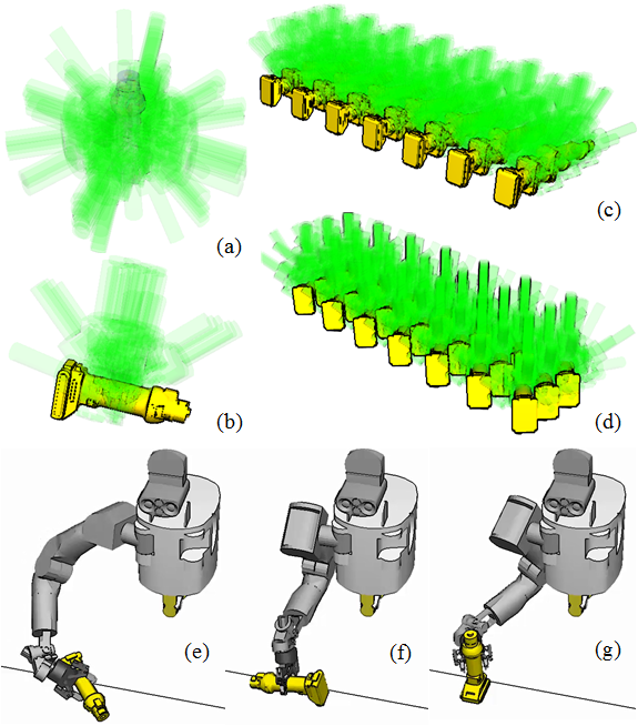
Fig.6 visualizes some of the tables. Fig.6(a) and (b) show the freeairgrip and freetabletopgrip of an electric drill object. Fig.6(c) and (d) show two rotated tabletopgrips. Fig.6(e)-(g) show some feasible IKs with respect to a humanoid robot with an 8-DoF (Degree of Freedom) arm (name: HRP5P).
V Roadmap-based Regrasp Graph
The data and relationships saved in the RDB make it easy to build the graph. Using them, we can analyze the combinatorics of grasps and placements, and build regrasp graphs on a table in front of a robot. The graph encodes the positions all over the table like a roadmap (Fig.7).
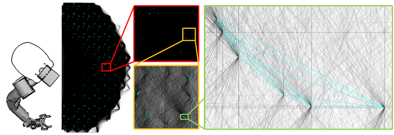
Building the graph The nodes of the graph are from the tabletopgrips table. Each node indicates one grasp configuration. The edges of the graph are converted from the relationships of tabletopplacements, tabletopgrips, and freeairgrip. Two nodes are connected using a transfer edge when the two rows of tabletopgrips share the same idfreeairgrip, which means a robot could grasp the object at one placement (one row of tabletopplacements) using a grasp configuration and transfer the object to another placement (another row of tabletopplacements) using the same grasp configuration. Two nodes are connected using a transit edge when the two rows of the tabletopgrips share the same idtabletopplacements, which means a robot could release the object grasped by a grasp configuration (one node at one end of the edge), transit to a different grasp configuration (the node at the other end of the edge), and grasp the object again using the second grasp configuration.
One example of the regrasp graph using tabletopplacements is shown in Fig.7. There are 2912 placements in the graph. These placements are at 91 positions on the table in front of a robot. At each position, the object could be posed at 4 different stable placements with 8 discretized rotations around vertical axis. The available grasps of a placement (a stable placement at a specific orientation) are connected to each other using transit edges (cyan). The shared grasps of different placements are connected to each other using transfer edges (black).
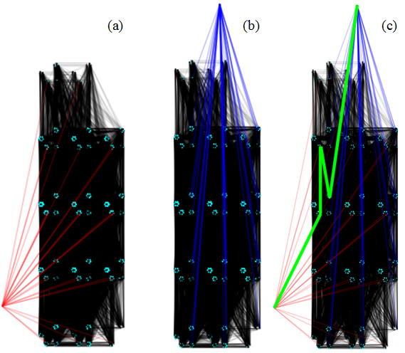
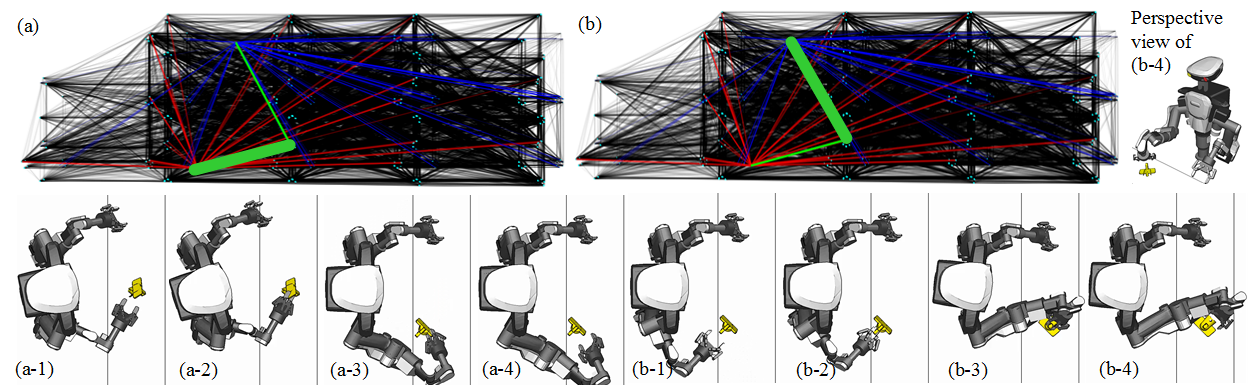
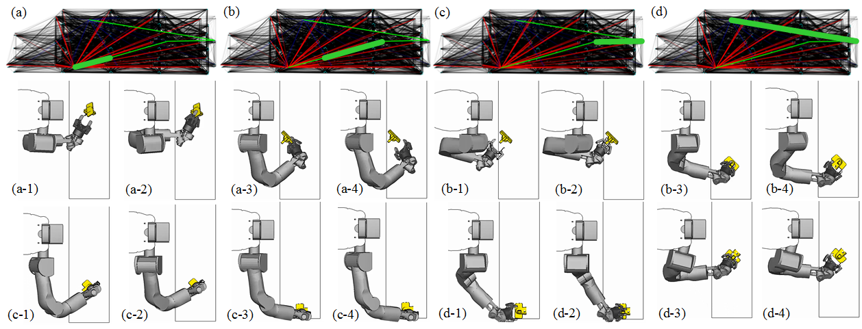
Searching the graph Once built, the regrasp graph can be used repeatedly for the same object. A vision system detects the initial pose of the object. The user inputs the goal pose of the object. The graph searching algorithm computes the available grasps of the initial and goal poses, and connects them to the roadmap. An example is shown in Fig.8. The initial placement and their available grasps are connected to the graph using red edges. The goal placement and their available grasps are connected to the graph using blue edges. The graph searching algorithm finds a path (green) from one of the initial grasps to one of the goal grasps. There might be several candidate paths, which could be selected using some criteria.
VI Experiments and Experiences
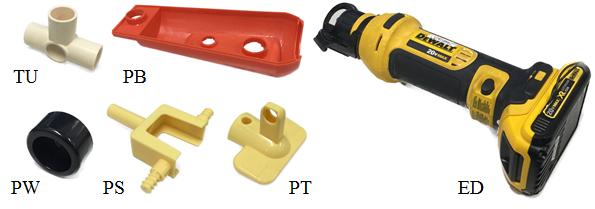
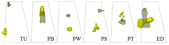
The proposed algorithms are validated using various objects and robots. The objects used include (Fig.9): (1) A plastic tube (TU), (2) a toy plane body (PB), (3) a toy plane wheel (PW), (4) a toy plane support (PS), (5) a toy plane tail (PT), and (6) an electric drill (ED). The robots used include: (1) HRP5P, which is a humanoid robot developed by our institute, and (2) Kawada Nextage, which is a commercially available industrial dual-arm robot. For each robot, a single arm is used. The processor of our computer is Intel Xeon 2.8GHz. Its graphic card is NVIDIA Quadro M3000M.
The tasks used to validate the algorithms are shown in Fig.10. Robots need to reorient the objects from the poses rendered in solid yellow to the poses in transparent yellow.
| obj | #-tri | #-fg | t-fg | #-fp | #-fpg | t-fp | #-tp | #-tpg | t-tpgikn | t-tpgikh | gsn | gsh | nrn | nrh |
|---|---|---|---|---|---|---|---|---|---|---|---|---|---|---|
| TU | 1640 | 84 | 10.43 | 6 | 0,38,1,18,33,21 | 6.45 | 1,008 | 18,648 | 1,746.67 | 1,692.74 | 5.51 | 15.52 | 1 | 3 |
| PB | 2786 | 1 | 10.33 | 2 | 0,1 | 0.51 | 336 | 168 | 4,025.69 | 4,069.84 | 0.14 | 0.17 | 0 | 0 |
| PW | 936 | 312 | 5.93 | 2 | 77,84 | 12.38 | 336 | 27,048 | 2,200.94 | 2,346.49 | 15.82 | 30.91 | 0 | 1 |
| PS | 13,662 | 157 | 101.76 | 3 | 97,44,35 | 9.36 | 504 | 29,568 | 16.46 | 16.09 | 8.62 | 28.01 | 2 | 2 |
| PT | 18,066 | 202 | 218.72 | 4 | 46,64,65,47 | 15.91 | 672 | 37,296 | 2,680.36 | 2,679.52 | 11.39 | 25.08 | 1 | 3 |
| ED | 34,960 | 118 | 700.94 | 5 | 106,25,21,41,44 | 8.43 | 840 | 39,816 | 3,186.77 | 2,891.07 | 7.95 | 28.91 | 1 | 1 |
-
Meanings of the abbreviations: obj – object name, #-tri – number of triangle meshes in the object’s mesh model, #-fg – number of free grasps (without consider obstacles, see freeairgrip in RDB), t-fg – the time needed to compute the free grasps, #-fp – number of free placements (without displacements and rotations, see freetabletopplacement in RDB), #-fpg – the number of available grasps for each free placement of the object (see freetabletopgrip in RDB), t-fp – the time needed to compute the free placements and update their available grasps, #-tp – number of total placements on the table (see tabletopplacements in RDB), #-tpg - the number of available grasps for all placements, t-tpgikn – the time needed to solve the IK of all grasps for Nextage, t-tpgikh – the time needed to solve the IK of all grasps for HRP5P, gsn – the time needed to connect the initial and goal grasps to the regrasp graph and search a path for Nextage, gsh – the time needed to connect the initial and goal grasps to the regrasp graph and search a path for HRP5P, nrn – the number of regrasps needed to reorient the object by Nextage, nrh – the number of regrasps needed to reorient the object by HRP5P.
Computational cost The size of the database and the time cost of the various planning algorithms are shown in Table.I. The meanings of the abbreviations are in the footnote of the table. The columns before the vertical separator are the volume of the data and the general cost to prepare the data. Particularly, the columns colored in gray are fully off-line. The columns colored in brown are flexible, depending on how complete practitioners would like the planner to be. For a table with a fixed height, they can be fully off-line. For tables with varying heights, they must be recomputed. 10,000 of grasps are planned and saved for regrasp planning (see the #-tpg column). The columns after the vertical separator show the specific costs of the tasks in Fig.10. The time used to compute the IK-feasible grasps at initial and goal poses, connect the grasps to the regrasp graph, and search the graph for the two robots are shown in the gsn (Nextage) and gsh (HRP5P) columns. They are in interactive time using the shown data volume. The values of gs depend on #-fpg and #-tpg (the columns colored in light purple). For example, the PW task has more #-fpg and #-tpg and therefore costs more. The PB task has few #-fpg and #-tpg and costs less than 0.2 (the success rate is lower). The times of regrasps are shown in the nrr (Nextage) and nrh (HRP5P) columns. The Nextage robot has better kinematic design to reorient the objects in some tasks: It used 1, 0, and 1 regrasps to reorient objects TU, PW, and PT. In contrast, the HRP5P robot used 3, 1, and 3 times of regrasps to reorient them. Also, one arm of HRP5P has 8 DoFs and costs more to do connecting and searching (including the shoulder and waist; One arm of Nextage has 7 DoFs).
Planned sequences Some planned manipulation sequence for the two robots to reorient object PT (task Fig.10(PT)) are shown in Fig.11 and Fig.12. The Nextage Robot has more flexibility than the HRP5P robot in this workspace. It used one regrasp to finish the task. In contrast, the HRP5P robot used three regrasps. The perspective view of Fig.11(b-4) is shown in the upper left corner of Fig.11. The robot is at a pose which is not reachable by HRP5P.
Experiences During the implementation, we carefully designed several parameters including: (1) Density of surface sampling, (2) stability of a placement, (3) resistance to torque caused by gravity, etc. The density of surface sampling is crucial to the number of automatically planned grasps and computational feasibility. The stability is essential to reduce accumulated errors and achieve high success rate during regrasp. The resistance to torque and gravity is important to certainty of grasps and stability during reorient. To make them general, we computed the density of sampling using the size of mesh surfaces, computed the stability of a placement using the ratio between the height of and the distance to the boundary of the supporting polygon, and filtered the resistance to torque caused by gravity by adding thresholds to the distance between the contact center and the of the object. These strategies are adaptive to varying model geometry (see Fig.10 and the #-tri column of Table.I), but they cannot be adaptive to varying physical properties like Coulumb coefficients, uneven density, etc. Dealing with uncertainties caused by these physical properties is an open problem.
VII Conclusions
In this paper, we developed intelligent algorithms for robots to reorient objects using 10,000 grasps. We developed robust grasp planning algorithms to plan the grasps and used RDB to manage the automatically planned data. These data were reused during regrasp planning to build regrasp roadmaps and find robot-pose and grasp-configuration sequences to reorient objects. Experiments showed the developed algorithm with the support of the database can reuse 10,000 of grasps to reorient objects at various poses in interactive time. We conclude that (1) the grasp planning algorithms are robust to find more grasps, (2) the relational database successfully manages the large amount of data generated by planning algorithms, and (3) the algorithms leverage modern computational ability to challenge the relationships and the combinatorics of the data. They are applicable to various robots and objects.
Acknowledgment
The paper is based on results obtained from a project commissioned by the New Energy and Industrial Technology Development Organization (NEDO).
References
- [1] P. Tournassound et al., “Regrasping,” in Proceedings of International Conference on Robotics and Automation, 1987, pp. 1924–1928.
- [2] F. Rohrdanz et al., “Generating and Evaluating Regrasp Operations,” in Proceedings of International Conference on Robotics and Automation, 1997, pp. 2013–2018.
- [3] H. Terasaki et al., “Motion Planning of Intelligent Manipulation by a Parallel Two-Fingered Gripper Equiped with a Simple Rotating Mechanism,” IEEE Transactions on Robotics and Automation, pp. 207–219, 1998.
- [4] S. A. Stoeter et al., “Planning of Regrasp Operations,” in Proceedings of International Conference on Robotics and Automation, 1999, pp. 245–250.
- [5] K. Cho et al., “Complete and Rapid Regrasp Planning with Look-up Table,” Journal of Intelligent and Robotic Systems, pp. 371–387, 2003.
- [6] Z. Xue et al., “Planning Regrasp Operations For a Multifingered Robotic Hand,” in Proceedings of International Conference on Automation Sicence and Engineering, 2008, pp. 778–783.
- [7] A. T. Miller et al., “Automatic Grasp Planning Using Shape Primitives,” in Proceedings of International Conference on Robotics and Automation, 2003, pp. 1824–1829.
- [8] J.-P. Saut et al., “Planning Pick-and-place Tasks with Two-hand Regrasping,” in Proceedings of International Conference on Intelligent Robots and Sytems, 2010, pp. 4528–4533.
- [9] J. King et al., “Regrasp Manipulation as Trajectory Optimization,” in Proceedings of Robotics: Science and Systems, 2013.
- [10] T. Simeon et al., “Manipulation Planning with Probabilistic Roadmaps,” International Journal of Robotics Research, vol. 23, pp. 729–746, 2004.
- [11] K. Hauser et al., “Multi-modal Motion Planning in Non-expansive Spaces,” International Journal of Robotics Research, pp. 897–915, 2010.
- [12] E. Yoshida et al., “Planning Whole-body Humanoid Locomotion, Reaching and Manipulation,” Motion Planning for Humanoid Robots, pp. 99–128, 2010.
- [13] B. Cohen et al., “Planning Single-arm Manipulations with N-Arm Robots,” in Proceedings of Robotics: Science and Systems, 2010.
- [14] A. Nguyen et al., “Preparatory object reorientation for task-oriented grasping,” in Proceedings of International Conference on Intelligent Robots and Systems, 2016, pp. 893–899.
- [15] “Preparatory Object Rotation as a Human-Inspired Grasping Strategy,” in Proceedings of IEEE-RAS International Conference on Humanoid Robots, 2008, pp. 527– 534.
- [16] P. Lertkultanon et al., “A Single-query Manipulation Planner,” IEEE Robotics and Automation Letters, 2016.
- [17] A. Krontiris et al., “Dealing with Difficult Instances of Object Rearrangement,” in Proceedings of : Science and Systems, 2015.
- [18] S. Jentzsch et al., “MOPL: A multi-modal path planner for generic manipulation tasks,” in Proceedings of the IEEE/RSJ International Conference on Intelligent Robots and Systems, 2015, pp. 6208–6214.
- [19] G. Lee et al., “Hierarchical planning for multi-contact non-prehensile manipulation,” in Proceedings of International Conference on Intelligent Robots and Sytems, 2015.